BAHAGIAN A – Pengesahan Kerjasama* · dianggap cekap apabila mengelolakan beban yang berciri...
40
BAHAGIAN A – Pengesahan Kerjasama* Adalah disahkan bahawa projek penyelidikan tesis ini telah dilaksanakan melalui kerjasama antara ______________________ dengan _________________________ Disahkan oleh: Tandatangan : ............................................................ Tarikh : ............... Nama : ............................................................ Jawatan : ............................................................ (Cop rasmi) * Jika penyediaan tesis/projek melibatkan kerjasama. BAHAGIAN B – Untuk Kegunaan Pejabat Pusat Pengajian Siswazah Tesis ini telah diperiksa dan diakui oleh: Nama dan Alamat Pemeriksa Luar : Prof. Dr. Masjuki Bin Hassan Director ………………………………………Energy Sciences Research Centre Faculty of Engineering ................................... University of Malaya ...................................... 50603 KUALA LUMPUR …………………………………………….. Nama dan Alamat Pemeriksa Dalam : Prof. Dr. Mat Nawi Bin Wan Hassan....... Faculty Kejuruteraan Mekanikal ............. UTM, Skudai .............................................. Nama Penyelia Lain (jika ada) : ...................................................................... ...................................................................... ...................................................................... Disahkan oleh Penolong Pendaftar di SPS: Tandatangan : ................................................................. Tarikh : ................... Nama : …KHASIM BIN ISMAIL…………………………………………
Transcript of BAHAGIAN A – Pengesahan Kerjasama* · dianggap cekap apabila mengelolakan beban yang berciri...
BAHAGIAN A – Pengesahan Kerjasama* Adalah disahkan bahawa projek penyelidikan tesis ini telah dilaksanakan melalui
kerjasama antara ______________________ dengan _________________________
Disahkan oleh:
Tandatangan : ............................................................ Tarikh : ...............
Nama : ............................................................
Jawatan : ............................................................
(Cop rasmi)
* Jika penyediaan tesis/projek melibatkan kerjasama.
BAHAGIAN B – Untuk Kegunaan Pejabat Pusat Pengajian Siswazah
Tesis ini telah diperiksa dan diakui oleh:
Nama dan Alamat Pemeriksa Luar : Prof. Dr. Masjuki Bin Hassan
Director
………………………………………Energy Sciences Research Centre
Faculty of Engineering ...................................
University of Malaya ......................................
50603 KUALA LUMPUR
……………………………………………..
Nama dan Alamat Pemeriksa Dalam : Prof. Dr. Mat Nawi Bin Wan Hassan.......
Faculty Kejuruteraan Mekanikal.............
UTM, Skudai ..............................................
Nama Penyelia Lain (jika ada) : ......................................................................
......................................................................
......................................................................
Disahkan oleh Penolong Pendaftar di SPS:
Tandatangan : ................................................................. Tarikh : ...................
Nama : …KHASIM BIN ISMAIL…………………………………………
ENHANCEMENT AND ANALYSIS OF A HYBRID LIQUID
DESICCANT BASED-COOLING SYSTEM
ELHADI BADAWI MAHGOUB
A thesis submitted in fulfilment of the
requirements for the award of the degree of
Doctor of Philosophy (Mechanical Engineering)
Faculty of Mechanical Engineering
Universiti Teknologi Malaysia
JULY 2007
iii
To the spirits of my father and mother, to my wife Ghada,
beloved sons Mohamed, Badawi, and Majdi, to my
brother Mohamed and sisters.
iv
ACKNOWLEDGEMNT
All praises and glory to almighty Allah “subhaanahu wa Ta’ala” for
bestowing me health, knowledge and patience to complete this thesis. Peace and
blessing of Allah be upon his Prophet Mohamed (Sallallaho Alaihi Wa salla)
My sincere thanks to my supervisors Prof. Dr. Farid Nasir Hj Ani and Prof.
Dr. K. S. Kannan for their guidance, encouragement, and support throughout the
course of this research. They continuously provided advice as well as constructive
criticism.
I am also grateful to the staff of Faculty of Mechanical Engineering UTM for
their support and encouragement. Technical assistance and help from the staff of
thermodynamic laboratory UTM is appreciated. My sincere thanks to my
international colleagues for their contribution. My special thanks and gratitude to my
colleagues from SUDAN whom their continuous support and care give me the
momentum to finish this thesis.
I am indebted to UTM, AL-IMAM AL-MAHDI UNIVERSITY, and the
Ministry of Science, Technology and Innovation for their financial support and for
giving me this opportunity to study.
I owe my sincere thanks and gratefulness to my wife Ghada, sons Mohamed,
Badawi, and Majdi, to my brother Mohamed, and my sisters for their continuing
encouragement, patience, and support financially and morally. Last but not least to
ALLAH, and to the spirit of my father and mother I dedicate this thesis.
v
ABSTRACT
Air conditioning has traditionally been achieved by vapour compression equipment, which is considered very efficient when handling loads characterised by high sensible load fraction. These machines would perform poorly when they process air with high latent load fraction as in the case of humid climates. Global energy concern has accelerated the research on alternative technology options to replace traditional method or improve their performance. Hybrid liquid desiccant system has been proposed as an energy saving alternative to reduce the vapour compression unit size used in air conditioning application, and improve its performance. A hybrid system consisting of vapour compression unit, a liquid desiccant system consisting of an absorber and a regenerator, both of which are identical packed spray towers built from fibre glass with a cross sectional area of 600 x 600 mm from five pieces each. Each piece having a height of 200 mm to facilitate testing different heights of packing material, and a flat plate solar hot water collector with an auxiliary electrical heater to be used as supplement when solar energy is not enough or not available. This hybrid system was designed, fabricated and tested with emphasis on liquid desiccant sub-system. In this study, the performance of the absorber and the regenerator, which are the main items in the liquid desiccant system, was studied in terms of effectiveness. Both units were tested over a range of different inlet liquid desiccant concentration of 20% to 40% by weight, and inlet temperature of 20oC, 25oC, and 30oC for the absorber, and 20%, 25% and 30% liquid desiccant concentration at temperature range of 35oC to 55oC for the regenerator. Both components were tested at liquid desiccant flow rate between 3.76 to 5.01 ℓ/min with different air inlet flow rate 4.9 to 6.4 m3/min. Experimental results were recorded using a complete data acquisition system to collect and log the data of the desiccant sub-system and the vapour compression unit, which enables thermocouples readings. From the data collected, the coefficient of performance of the vapour compression unit was obtained using both refrigerant enthalpy and air enthalpy methods. Absorber effectiveness was found to be between 0.5 and 0.7, while the regenerator effectiveness was found to be between 0.2 and 0.6. A 800 mm packing height is found to be the breaking limit with both air supply either fully through the desiccant or partly (50% through the desiccant), would result in an improvement in the performance of the vapour compression unit ranging from 17.9 % to 54%, which indicate the hybrid system potential for energy savings. Improving indoor air quality by controlling humidity, killing effect of bacteria and fungus by using liquid desiccant are among other benefits realised.
vi
ABSTRAK
Penghawadinginan biasanya dilakukan oleh alat mampatan wap, yang boleh
dianggap cekap apabila mengelolakan beban yang berciri pecahan beban ketara yang tinggi. Mesin ini akan berkelakuan dengan tidak memuaskan apabila memproses udara dengan pecahan beban pendam yang tinggi seperti dalam kes iklim lembab. Kebimbangan global tenaga telah mempercepatkan penyelidikan keatas opsyen teknologi alternatif untuk menggantikan kaedah tradisional atau meningkatkan prestasinya. Sistem pengering cecair hibrid yang telah dicadangkan sebagai penjimatan tenaga alternatif untuk mengurangkan saiz unit mampatan wap yang digunakan untuk penghawa dingin serta memperbaiki prestasi. Sistem hibrid mengandungi unit wap mampatan, sistem pengering cecair yang mengandungi penyerap dan penjana semula, kedua-duanya adalah menara penyembur padat yang serupa dibina daripada kaca gantian dengan luas keratan rentas 600 x 600 mm dari lima kepingan dimana setiap kepingan dengan ketinggian 200 mm untuk memudahkan ujian pada ketinggian berlainan bahan padat, dan satu pengumpul air panas suria plat rata dengan pemanas elektrik untuk digunakan sebagai tenaga tambahan sekiranya tenaga suria tidak mencukupi atau tidak ada. Sistem hibrid ini direkakan, dibina dan diuji dengan tumpuan kepada sub-sistem pengering cecair. Dalam kajian ini, prestasi penyerap dan penjana semula yang menjadi komponen utama dalam sistem pengering cecair dikaji dari segi sebutan keberkesanan. Kedua-duanya diuji pada julat kepekatan pengering cecair pada salur masuk yang berlainan dari 20% hingga 40% secara berat dan suhu salur masuk 20oC, 25oC dan 30oC bagi penyerap dan kepekatan pengering cecair 20%, 25% dan 30% pada julat suhu dari 35oC ke 55oC bagi penjana semula. Kedua-dua komponen diuji pada kadar aliran pengering cecair diantara 3.76 dan 5.01 ℓ/min, dengan kadar aliran salur masuk udara dari 4.9 hingga 6.4 m3/min. Keputusan ujikaji direkod dengan menggunakan sistem pengumpulan data yang lengkap untuk mengumpul dan menyimpan data sub-sistem pengering serta unit mampatan wap yang mencatat bacaan termogandingan. Dari data yang dikumpul, pekali prestasi unit mampatan wap telah diperolehi dengan kedua-dua kaedah entalpi penyejukan dan udara. Keberkesanan penyerap didapati antara 0.5 dan 0.7, manakala keberkesanan penjana semula didapati antara 0.2 dan 0.6. Padatan setinggi 800 mm adalah dikenalpasti sebagai had pecahan dengan kedua-dua bekalan udara samada sepenuhnya melalui pengering atau sebahagiannya (50% melalui pengering) yang akan mengakibatkan peningkatan prestasi unit mampatan wap berjulat dari 17.9% hingga 54%. Ini menandakan potensi sistem hibrid bagi penjimatan tenaga. Peningkatan kualiti udara dalaman dengan mengawal kelembapan, membunuh bakteria dan fungus dengan menggunakan pengering cecair adalah antara faedah lain yang terhasil.
vii
TABLE OF CONTENTS
CHAPTER TITLE PAGE
DECLARATION ii
DEDICATION iii
ACKNOWLEDGMENT iv
ABSTRACT v
ABSTRAK vi
TABLE OF CONTENTS vii
LIST OF TABLES xi
LIST OF FIGURES xx
LIST OF SYMBOL xxv
LIST OF APPENDICES xxvi
1 INTRODUCTION 1
1.1 Background 1
1.2 Global Warming and Refrigerants 2
1.3 Market Forces 3
1.4 Problem Statement 4
1.5 Research Scope 5
1.6 Research Objectives 6
1.7 Thesis Outline 6
2 LITERATURE REVIEW 8
2.1 Introduction 8
2.2 Solar Assisted Desiccant Systems 8
2.3 Gas Fired Solid Desiccant Systems 12
2.4 Other Desiccant Related Work 15
viii
2.5 Liquid Desiccant 16
2.6 Regeneration of Liquid Desiccant 16
2.6.1 Regeneration Using Solar Energy 17
2.6.2 Regeneration Using Waste Heat Recovery 19
2.6.3 Regeneration Using Gas Boiler 19
2.7 Hybrid Liquid Desiccant Systems 19
2.8 Desiccant Aided Chilled Ceiling 23
2.8.1 Advantages of Desiccant Aided Chilled Ceiling 24
2.8.1 Disadvantages of Desiccant Aided Chilled Ceiling 25
3 THEORETICAL FRAMEWORK 27
3.1 Introduction 27
3.2 Needs for Air –Conditioning 27
3.3 Air Conditioning Loads 28
3.4 Common Air Conditioning Systems 29
3.4.1 Vapour Compression Equipment and Cycle 29
3.5 Dehumidification 34
3.5.1 The Dehumidifier 36
3.5.2 The Cooling Unit 37
3.5.3 Regeneration Heat Source 38
3.6 Desiccant Dehumidification 38
3.7 Desiccants 39
3.8. Types of Desiccants 39
3.19 Liquid Absorbents 40
3.10 Desiccant Cycle 42
3.11 Common Desiccant Applications 45
3.12 Desiccant Characteristics for Commercial
Dehumidifying 45
3.13 Advantages of Desiccant Systems over
Conventional Methods 46
3.14 Advantages of Liquid Desiccants over Solid
Desiccants 47
3.15 Coefficient of Performance Calculated Based on
Refrigerant Enthalpy 48
ix
3.16 Coefficient of Performance Calculated Based on
Air Enthalpy 49
3.17 Calculating Absorber Effectiveness 50
3.18 Calculating Regenerator Effectiveness 51
4 EXPERIMENTAL RIG AND RESEARCH
METHODOLOGY 52
4.1 Introduction 52
4.2 Description of The Test Rig 52
4.2.1 Description of The Liquid Desiccant Sub-System 53
4.2.1.1 Desiccant Flow 53
4.2.1.2 Air Flow 61
4.2.1.3 Cooling and Heating Water Flow 62
4.2.2 Description of The Vapour Compression Unit 62
4.2.3 Flat Plate Solar Hot Water Collector 63
4.3 Research Procedure 64
4.4 Instrumentation and Data Collection 64
4.4.1 Design Variables 65
4.4.2 Independent Variables 67
4.4.3 Dependent Variables 67
4.4.4 Other Variables 68
4.5 Method of Testing The Hybrid Desiccant Cooling System 68
5 RESULTS AND DISCUSSIONS 71
5.1 Introduction 71
5.2 Packing Height Results and Discussion 71
5.3 Liquid Desiccant and Air Flow Rate Results and
Discussion 120
5.4 Absorber Dehumidification Effectiveness 131
5.5 Regenerator Effectiveness Results 136
5.6 Benefit of Using A Liquid Desiccant In The Hybrid
System 142
5.7 Contribution of The Study 142
5.8 Comparison With Other Results in The Literature 143
x
6 CONCLUSIONS AND RECOMMENDATIONS 144
6.1 Conclusions 144
6.2 Recommendations for Future Work 146
REFERENCES 148
Appendices 1-6 155-164
xi
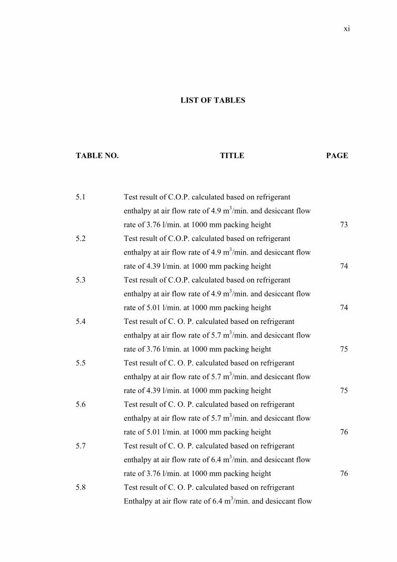
LIST OF TABLES
TABLE NO. TITLE PAGE
5.1 Test result of C.O.P. calculated based on refrigerant
enthalpy at air flow rate of 4.9 m3/min. and desiccant flow
rate of 3.76 l/min. at 1000 mm packing height 73
5.2 Test result of C.O.P. calculated based on refrigerant
enthalpy at air flow rate of 4.9 m3/min. and desiccant flow
rate of 4.39 l/min. at 1000 mm packing height 74
5.3 Test result of C.O.P. calculated based on refrigerant
enthalpy at air flow rate of 4.9 m3/min. and desiccant flow
rate of 5.01 l/min. at 1000 mm packing height 74
5.4 Test result of C. O. P. calculated based on refrigerant
enthalpy at air flow rate of 5.7 m3/min. and desiccant flow
rate of 3.76 l/min. at 1000 mm packing height 75
5.5 Test result of C. O. P. calculated based on refrigerant
enthalpy at air flow rate of 5.7 m3/min. and desiccant flow
rate of 4.39 l/min. at 1000 mm packing height 75
5.6 Test result of C. O. P. calculated based on refrigerant
enthalpy at air flow rate of 5.7 m3/min. and desiccant flow
rate of 5.01 l/min. at 1000 mm packing height 76
5.7 Test result of C. O. P. calculated based on refrigerant
enthalpy at air flow rate of 6.4 m3/min. and desiccant flow
rate of 3.76 l/min. at 1000 mm packing height 76
5.8 Test result of C. O. P. calculated based on refrigerant
Enthalpy at air flow rate of 6.4 m3/min. and desiccant flow
xii
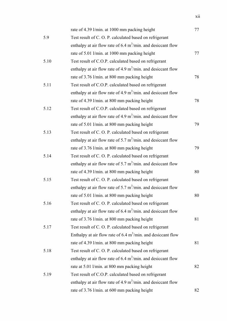
rate of 4.39 l/min. at 1000 mm packing height 77
5.9 Test result of C. O. P. calculated based on refrigerant
enthalpy at air flow rate of 6.4 m3/min. and desiccant flow
rate of 5.01 l/min. at 1000 mm packing height 77
5.10 Test result of C.O.P. calculated based on refrigerant
enthalpy at air flow rate of 4.9 m3/min. and desiccant flow
rate of 3.76 l/min. at 800 mm packing height 78
5.11 Test result of C.O.P. calculated based on refrigerant
enthalpy at air flow rate of 4.9 m3/min. and desiccant flow
rate of 4.39 l/min. at 800 mm packing height 78
5.12 Test result of C.O.P. calculated based on refrigerant
enthalpy at air flow rate of 4.9 m3/min. and desiccant flow
rate of 5.01 l/min. at 800 mm packing height 79
5.13 Test result of C. O. P. calculated based on refrigerant
enthalpy at air flow rate of 5.7 m3/min. and desiccant flow
rate of 3.76 l/min. at 800 mm packing height 79
5.14 Test result of C. O. P. calculated based on refrigerant
enthalpy at air flow rate of 5.7 m3/min. and desiccant flow
rate of 4.39 l/min. at 800 mm packing height 80
5.15 Test result of C. O. P. calculated based on refrigerant
enthalpy at air flow rate of 5.7 m3/min. and desiccant flow
rate of 5.01 l/min. at 800 mm packing height 80
5.16 Test result of C. O. P. calculated based on refrigerant
enthalpy at air flow rate of 6.4 m3/min. and desiccant flow
rate of 3.76 l/min. at 800 mm packing height 81
5.17 Test result of C. O. P. calculated based on refrigerant
Enthalpy at air flow rate of 6.4 m3/min. and desiccant flow
rate of 4.39 l/min. at 800 mm packing height 81
5.18 Test result of C. O. P. calculated based on refrigerant
enthalpy at air flow rate of 6.4 m3/min. and desiccant flow
rate at 5.01 l/min. at 800 mm packing height 82
5.19 Test result of C.O.P. calculated based on refrigerant
enthalpy at air flow rate of 4.9 m3/min. and desiccant flow
rate of 3.76 l/min. at 600 mm packing height 82
xiii
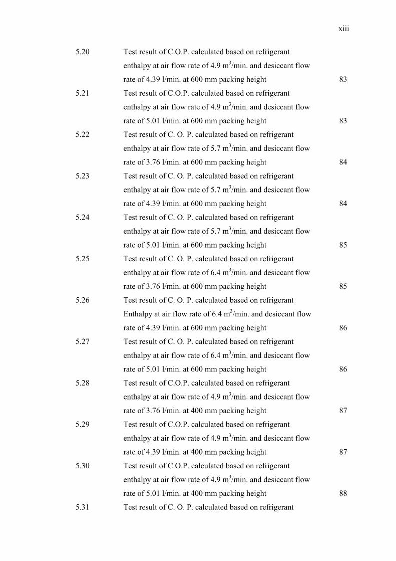
5.20 Test result of C.O.P. calculated based on refrigerant
enthalpy at air flow rate of 4.9 m3/min. and desiccant flow
rate of 4.39 l/min. at 600 mm packing height 83
5.21 Test result of C.O.P. calculated based on refrigerant
enthalpy at air flow rate of 4.9 m3/min. and desiccant flow
rate of 5.01 l/min. at 600 mm packing height 83
5.22 Test result of C. O. P. calculated based on refrigerant
enthalpy at air flow rate of 5.7 m3/min. and desiccant flow
rate of 3.76 l/min. at 600 mm packing height 84
5.23 Test result of C. O. P. calculated based on refrigerant
enthalpy at air flow rate of 5.7 m3/min. and desiccant flow
rate of 4.39 l/min. at 600 mm packing height 84
5.24 Test result of C. O. P. calculated based on refrigerant
enthalpy at air flow rate of 5.7 m3/min. and desiccant flow
rate of 5.01 l/min. at 600 mm packing height 85
5.25 Test result of C. O. P. calculated based on refrigerant
enthalpy at air flow rate of 6.4 m3/min. and desiccant flow
rate of 3.76 l/min. at 600 mm packing height 85
5.26 Test result of C. O. P. calculated based on refrigerant
Enthalpy at air flow rate of 6.4 m3/min. and desiccant flow
rate of 4.39 l/min. at 600 mm packing height 86
5.27 Test result of C. O. P. calculated based on refrigerant
enthalpy at air flow rate of 6.4 m3/min. and desiccant flow
rate of 5.01 l/min. at 600 mm packing height 86
5.28 Test result of C.O.P. calculated based on refrigerant
enthalpy at air flow rate of 4.9 m3/min. and desiccant flow
rate of 3.76 l/min. at 400 mm packing height 87
5.29 Test result of C.O.P. calculated based on refrigerant
enthalpy at air flow rate of 4.9 m3/min. and desiccant flow
rate of 4.39 l/min. at 400 mm packing height 87
5.30 Test result of C.O.P. calculated based on refrigerant
enthalpy at air flow rate of 4.9 m3/min. and desiccant flow
rate of 5.01 l/min. at 400 mm packing height 88
5.31 Test result of C. O. P. calculated based on refrigerant
xiv
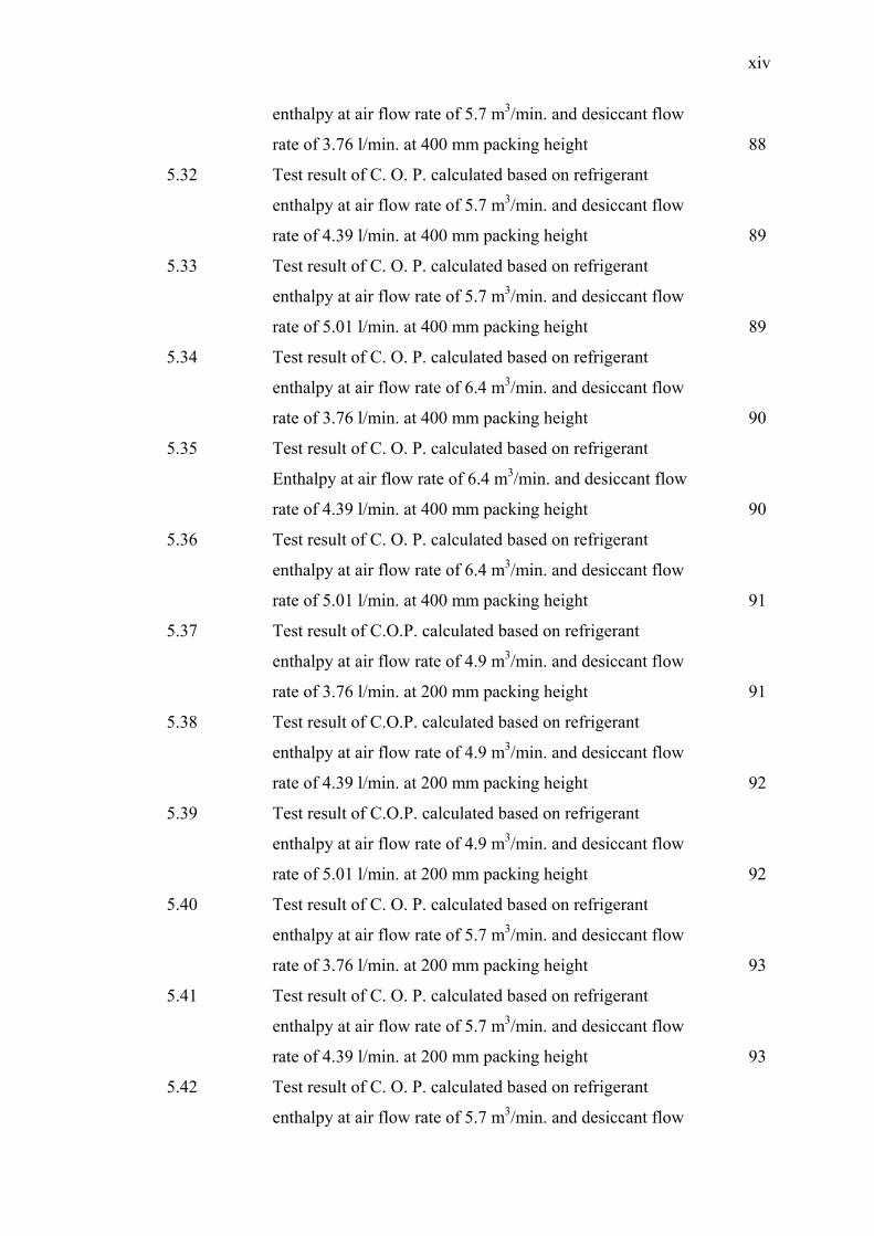
enthalpy at air flow rate of 5.7 m3/min. and desiccant flow
rate of 3.76 l/min. at 400 mm packing height 88
5.32 Test result of C. O. P. calculated based on refrigerant
enthalpy at air flow rate of 5.7 m3/min. and desiccant flow
rate of 4.39 l/min. at 400 mm packing height 89
5.33 Test result of C. O. P. calculated based on refrigerant
enthalpy at air flow rate of 5.7 m3/min. and desiccant flow
rate of 5.01 l/min. at 400 mm packing height 89
5.34 Test result of C. O. P. calculated based on refrigerant
enthalpy at air flow rate of 6.4 m3/min. and desiccant flow
rate of 3.76 l/min. at 400 mm packing height 90
5.35 Test result of C. O. P. calculated based on refrigerant
Enthalpy at air flow rate of 6.4 m3/min. and desiccant flow
rate of 4.39 l/min. at 400 mm packing height 90
5.36 Test result of C. O. P. calculated based on refrigerant
enthalpy at air flow rate of 6.4 m3/min. and desiccant flow
rate of 5.01 l/min. at 400 mm packing height 91
5.37 Test result of C.O.P. calculated based on refrigerant
enthalpy at air flow rate of 4.9 m3/min. and desiccant flow
rate of 3.76 l/min. at 200 mm packing height 91
5.38 Test result of C.O.P. calculated based on refrigerant
enthalpy at air flow rate of 4.9 m3/min. and desiccant flow
rate of 4.39 l/min. at 200 mm packing height 92
5.39 Test result of C.O.P. calculated based on refrigerant
enthalpy at air flow rate of 4.9 m3/min. and desiccant flow
rate of 5.01 l/min. at 200 mm packing height 92
5.40 Test result of C. O. P. calculated based on refrigerant
enthalpy at air flow rate of 5.7 m3/min. and desiccant flow
rate of 3.76 l/min. at 200 mm packing height 93
5.41 Test result of C. O. P. calculated based on refrigerant
enthalpy at air flow rate of 5.7 m3/min. and desiccant flow
rate of 4.39 l/min. at 200 mm packing height 93
5.42 Test result of C. O. P. calculated based on refrigerant
enthalpy at air flow rate of 5.7 m3/min. and desiccant flow
xv
rate of 5.01 l/min. at 200 mm packing height 94
5.43 Test result of C. O. P. calculated based on refrigerant
enthalpy at air flow rate of 6.4 m3/min. and desiccant flow
rate of 3.76 l/min. at 200 mm packing height 94
5.44 Test result of C. O. P. calculated based on refrigerant
Enthalpy at air flow rate of 6.4 m3/min. and desiccant flow
rate of 4.39 l/min. at 200 mm packing height 95
5.45 Test result of C. O. P. calculated based on refrigerant
enthalpy at air flow rate of 6.4 m3/min. and desiccant flow
rate of 5.01 l/min. at 200 mm packing height 95
5.46 Test result of C. O. p. calculated based on air enthalpy
at air flow rate of 4.9 m3/min. and desiccant flow
rate of 3.76 l/min. at 1000 mm packing height 96
5.47 Test result of C. O. P. calculated based on air enthalpy
At air flow rate of 4.9 m3/min. and desiccant flow
rate of 4.39 l/min. at 1000 mm packing height 96
5.48 Test result of C. O. P. calculated based on air enthalpy
at air flow rate of 4.9 m3/min. and desiccant flow
rate of 5.01 l/min. at 1000 mm packing height 96
5.49 Test result of C. O. p. calculated based on air enthalpy
at air flow rate of 5.7 m3/min. and desiccant flow
rate of 3.76 l/min. at 1000 mm packing height 97
5.50 Test result of C. O. P. calculated based on air enthalpy
At air flow rate of 5.7 m3/min. and desiccant flow
rate of 4.39 l/min. at 1000 mm packing height 97
5.51 Test result of C. O. P. calculated based on air enthalpy
at air flow rate of 5.7 m3/min. and desiccant flow
rate of 5.01 l/min. at 1000 mm packing height 97
5.52 Test result of C. O. p. calculated based on air enthalpy
at air flow rate of 6.4 m3/min. and desiccant flow
rate of 3.76 l/min. at 1000 mm packing height 98
5.53 Test result of C. O. P. calculated based on air enthalpy
At air flow rate of 6.4 m3/min. and desiccant flow
rate of 4.39 l/min. at 1000 mm packing height 98
xvi
5.54 Test result of C. O. P. calculated based on air enthalpy
at air flow rate of 6.4 m3/min. and desiccant flow
rate of 5.01 l/min. at 1000 mm packing height 98
5.55 Test result of C. O. p. calculated based on air enthalpy
at air flow rate of 4.9 m3/min. and desiccant flow
rate of 3.76 l/min. at 800 mm packing height 99
5.56 Test result of C. O. P. calculated based on air enthalpy
At air flow rate of 4.9 m3/min. and desiccant flow
rate of 4.39 l/min. at 800 mm packing height 99
5.57 Test result of C. O. P. calculated based on air enthalpy
at air flow rate of 4.9 m3/min. and desiccant flow
rate of 5.01 l/min. at 800 mm packing height 99
5.58 Test result of C. O. p. calculated based on air enthalpy
at air flow rate of 5.7 m3/min. and desiccant flow
rate of 3.76 l/min. at 800 mm packing height 100
5.59 Test result of C. O. P. calculated based on air enthalpy
At air flow rate of 5.7 m3/min. and desiccant flow
rate of 4.39 l/min. at 800 mm packing height 100
5.60 Test result of C. O. P. calculated based on air enthalpy
at air flow rate of 5.7 m3/min. and desiccant flow
rate of 5.01 l/min. at 800 mm packing height 100
5.61 Test result of C. O. p. calculated based on air enthalpy
at air flow rate of 6.4 m3/min. and desiccant flow
rate of 3.76 l/min. at 800 mm packing height 101
5.62 Test result of C. O. P. calculated based on air enthalpy
At air flow rate of 6.4 m3/min. and desiccant flow
rate of 4.39 l/min. at 800 mm packing height 101
5.63 Test result of C. O. P. calculated based on air enthalpy
at air flow rate of 6.4 m3/min. and desiccant flow
rate of 5.01 l/min. at 800 mm packing height 101
5.64 Test result of C. O. p. calculated based on air enthalpy
at air flow rate of 4.9 m3/min. and desiccant flow
rate of 3.76 l/min. at 600 mm packing height 102
5.65 Test result of C. O. P. calculated based on air enthalpy
xvii
At air flow rate of 4.9 m3/min. and desiccant flow
rate of 4.39 l/min. at 600 mm packing height 102
5.66 Test result of C. O. P. calculated based on air enthalpy
at air flow rate of 4.9 m3/min. and desiccant flow
rate of 5.01 l/min. at 600 mm packing height 102
5.67 Test result of C. O. p. calculated based on air enthalpy
at air flow rate of 5.7 m3/min. and desiccant flow
rate of 3.76 l/min. at 600 mm packing height 103
5.68 Test result of C. O. P. calculated based on air enthalpy
At air flow rate of 5.7 m3/min. and desiccant flow
rate of 4.39 l/min. at 600 mm packing height 103
5.69 Test result of C. O. P. calculated based on air enthalpy
at air flow rate of 5.7 m3/min. and desiccant flow
rate of 5.01 l/min. at 600 mm packing height 103
5.70 Test result of C. O. p. calculated based on air enthalpy
at air flow rate of 6.4 m3/min. and desiccant flow
rate of 3.76 l/min. at 600 mm packing height 104
5.71 Test result of C. O. P. calculated based on air enthalpy
At air flow rate of 6.4 m3/min. and desiccant flow
rate of 4.39 l/min. at 600 mm packing height 104
5.72 Test result of C. O. P. calculated based on air enthalpy
at air flow rate of 6.4 m3/min. and desiccant flow
rate of 5.01 l/min. at 600 mm packing height 104
5.73 Test result of C. O. p. calculated based on air enthalpy
at air flow rate of 4.9 m3/min. and desiccant flow
rate of 3.76 l/min. at 400 mm packing height 105
5.74 Test result of C. O. P. calculated based on air enthalpy
At air flow rate of 4.9 m3/min. and desiccant flow
rate of 4.39 l/min. at 400 mm packing height 105
5.75 Test result of C. O. P. calculated based on air enthalpy
at air flow rate of 4.9 m3/min. and desiccant flow
rate of 5.01 l/min. at 400 mm packing height 105
5.76 Test result of C. O. p. calculated based on air enthalpy
at air flow rate of 5.7 m3/min. and desiccant flow
xviii
rate of 3.76 l/min. at 400 mm packing height 106
5.77 Test result of C. O. P. calculated based on air enthalpy
At air flow rate of 5.7 m3/min. and desiccant flow
rate of 4.39 l/min. at 400 mm packing height 106
5.78 Test result of C. O. P. calculated based on air enthalpy
at air flow rate of 5.7 m3/min. and desiccant flow
rate of 5.01 l/min. at 400 mm packing height 106
5.79 Test result of C. O. p. calculated based on air enthalpy
at air flow rate of 6.4 m3/min. and desiccant flow
rate of 3.76 l/min. at 400 mm packing height 107
5.80 Test result of C. O. P. calculated based on air enthalpy
At air flow rate of 6.4 m3/min. and desiccant flow
rate of 4.39 l/min. at 400 mm packing height 107
5.81 Test result of C. O. P. calculated based on air enthalpy
at air flow rate of 6.4 m3/min. and desiccant flow
rate of 5.01 l/min. at 400 mm packing height 107
5.82 Test result of C. O. p. calculated based on air enthalpy
at air flow rate of 4.9 m3/min. and desiccant flow
rate of 3.76 l/min. at 200 mm packing height 108
5.83 Test result of C. O. P. calculated based on air enthalpy
At air flow rate of 4.9 m3/min. and desiccant flow
rate of 4.39 l/min. at 200 mm packing height 108
5.84 Test result of C. O. P. calculated based on air enthalpy
at air flow rate of 4.9 m3/min. and desiccant flow
rate of 5.01 l/min. at 200 mm packing height 108
5.85 Test result of C. O. p. calculated based on air enthalpy
at air flow rate of 5.7 m3/min. and desiccant flow
rate of 3.76 l/min. at 200 mm packing height 109
5.86 Test result of C. O. P. calculated based on air enthalpy
At air flow rate of 5.7 m3/min. and desiccant flow
rate of 4.39 l/min. at 200 mm packing height 109
5.87 Test result of C. O. P. calculated based on air enthalpy
at air flow rate of 5.7 m3/min. and desiccant flow
rate of 5.01 l/min. at 200 mm packing height 109
xix
5.88 Test result of C. O. p. calculated based on air enthalpy
at air flow rate of 6.4 m3/min. and desiccant flow
rate of 3.76 l/min. at 200 mm packing height 110
5.89 Test result of C. O. P. calculated based on air enthalpy
At air flow rate of 6.4 m3/min. and desiccant flow
rate of 4.39 l/min. at 200 mm packing height 110
5.90 Test result of C. O. P. calculated based on air enthalpy
at air flow rate of 6.4 m3/min. and desiccant flow
rate of 5.01 l/min. at 200 mm packing height 110
xx
LIST OF FIGURES
FIGURE NO. TITLE PAGE
3.1 Vapour compression component and cycle. 30
3.2 The general p-h representation of vapour refrigeration
cycle. 31
3.3 Psychrometric schematic of supply air state in
vapour compression cycle 32
3.4 Different methods of dehumidification 35
3.5 Desiccant cooling system principles 36
3.6 General liquid desiccant system integrated with
vapour compression system. 41
3.7 General desiccant cycle 43
3.8 Pressure –enthalpy diagram of the vapour
compression cycle 48
4.1 The integrated tested rig diagram 54
4.2a The absorber of liquid desiccant system 55
4.2b The regenerator of the liquid desiccant system 56
4.2c The flat plate solar hot water collector with
auxiliary heater 57
4.2d The vapour compression unit with the
conditioned chamber 58
4.3 Back view of the test rig 59
xxi
4.4 Front and side view of the test rig 59
4.5 Flat plate solar hot water collector 60
4.6 CIO-EXP 32 and CIO-DAS 08 data acquisition cards 60
5.1a Coefficient of performance at air volume of 4.9 m3/min
and 3.76 l/min liquid desiccant flow rate. 111
5.1b Coefficient of performance at air volume of 4.9 m3/min
and 3.76 l/min liquid desiccant flow rate. 111
5.2a Coefficient of performance at air volume of 4.9 m3/min
and 4.39 l/min liquid desiccant flow rate. 112
5.2b Coefficient of performance at air volume of 4.9 m3/min
and 4.39 l/min liquid desiccant flow rate. 112
5.3a Coefficient of performance at air volume of 4.9 m3/min
and 5.01 l/min liquid desiccant flow rate. 113
5.3b Coefficient of performance at air volume of 4.9 m3/min
and 5.01 l/min liquid desiccant flow rate. 113
5.4a Coefficient of performance at air volume of 5.7 m3/min
and 3.76 l/min liquid desiccant flow rate. 114
5.4b Coefficient of performance at air volume of 5.7 m3/min
and 3.76 l/min liquid desiccant flow rate. 114
5.5a Coefficient of performance at air volume of 5.7 m3/min
and 4.39 l/min liquid desiccant flow rate. 115
5.5b Coefficient of performance at air volume of 5.7 m3/min
and 4.39 l/min liquid desiccant flow rate. 115
5.6a Coefficient of performance at air volume of 5.7 m3/min
and 5.01 l/min liquid desiccant flow rate. 116
5.6b Coefficient of performance at air volume of 5.7 m3/min
and 5.01 l/min liquid desiccant flow rate. 116
5.7a Coefficient of performance at air volume of 6.4 m3/min
and 3.76 l/min. liquid desiccant flow rate. 117
5.7b Coefficient of performance at air volume of 6.4 m3/min
and 3.76 l/min. liquid desiccant flow rate. 117
5.8a Coefficient of performance at air volume of 6.4 m3/min
and 4.39 l/min liquid desiccant flow rate. 118
5.8b Coefficient of performance at air volume of 6.4 m3/min
xxii
and 4.39 l/min liquid desiccant flow rate. 118
5.9a Coefficient of performance at air volume of 6.4 m3/min
and 5.01 l/min liquid flow rate. 119
5.9b Coefficient of performance at air volume of 6.4 m3/min
and 5.01 l/min liquid flow rate. 119
5.10 C.O.P. of the vapour compression unit when using
all air through desiccant at 1000 mm packing height
illustrating the different air flow rates of 4.9,
5.7, and 6.4 3/min. V. C. stands for vapour
compression alone. 123
5.11 C.O.P. of the vapour compression unit when using
50% air through desiccant and 50% from ambient
at 1000 mm packing height, illustrating the different
air flow rates of 4.9, 5.7, and 6.4 m3/min. V.C.
stands for vapour compression alone. 124
5.12 C.O.P. of the vapour compression unit when
using all air through desiccant at 800 mm packing height,
illustrating the different air flow rates of 4.9, 5.7, and
6.4 m3/min. V.C. stands for vapour compression alone. 125
5.13 C.O.P. of the vapour compression unit when using
50% air through desiccant and 50% from ambient,
at 800 mm packing height, illustrating the different air
flow rates of 4.9, 5.7, and 6.4 m3/min. V.C. stands for
vapour compression alone. 126
5.14 C.O.P. of the vapour compression unit when
using all air through desiccant, at 600 mm packing
height, illustrating the different air flow rates of
4.9, 5.7, and 6.4 m3/min. V. C. stands for vapour
compression alone. 127
5.15 C.O.P. of the vapour compression unit when
using 50% air through desiccant and 50% from
ambient, at 600 mm packing height, illustrating the
different air flow rates of 4.9, 5.7, and 6.4 m3/min. V.C.
stands for vapour compression alone. 128
xxiii
5.16 C.O.P. of the vapour compression unit when using
all air through desiccant, at 400 mm packing height,
illustrating the different air flow rates of 4.9, 5.7, and
6.4 m3/min. V.C. stands for vapour compression alone. 129
5.17 C.O.P. of the vapour compression unit when using
50% air through desiccant and 50% from ambient,
at 400 mm packing height, illustrating the different air
flow rates of 4.9, 5.7, and 6.4 m3/min. V.C. stands for
vapour compression alone. 130
5.18 Absorber effectiveness at air flow rate of 4.9 m3/min.
and at solution temperature of 20°C. 132
5.19 Absorber effectiveness at air flow rate of 4.9 m3/min.
and at solution temperature of 25 °C 132
5.20 Absorber effectiveness at process air flow rate of
4.9 m3/min and at solution temperature of 30° C 133
5.21 Absorber effectiveness at air flow rate of 5.7 m3/min.
and at solution temperature of 20°C. 133
5.22 Absorber effectiveness at air flow rate of 5.7 m3/min.
and at solution temperature of 25°C. 134
5.23 Absorber effectiveness at air flow rate of 5.7 m3/min.
and at solution temperature of 30°C. 134
5.24 Absorber effectiveness at air flow rate of 6.4 m3/min.
and at solution temperature of 20°C. 135
5.25 Absorber effectiveness at air flow rate of 6.4 m3/min.
and at solution temperature of 25°C. 135
5.26 Absorber effectiveness at air flow rate of 6.4 m3/min.
and at solution temperature of 30°C. 136
5.27 Regenerator effectiveness at liquid desiccant
concentration of 20 % by weight and at process air
flow volume of 4.9 m3/min. 138
5.28 Regenerator effectiveness at liquid desiccant
concentration of 25 % by weight and at process air
flow volume of 4.9 m3/min. 138
5.29 Regenerator effectiveness at liquid desiccant
xxiv
concentration of 30 % by weight and at process air
flow volume of 4.9 m3/min. 139
5.30 Regenerator effectiveness at liquid desiccant
concentration of 20 % by weight and at process air
flow volume of 5.7 m3/min. 139
5.31 Regenerator effectiveness at liquid desiccant
concentration of 25 % by weight and at process air
flow volume of 5.7 m3/min. 140
5.32 Regenerator effectiveness at liquid desiccant
concentration of 30 % by weight and at process air
flow volume of 5.7 m3/min. 140
5.33 Regenerator effectiveness at liquid desiccant
concentration of 20 % by weight and at process air
flow volume of 6.4 m3/min. 141
5.34 Regenerator effectiveness at liquid desiccant
concentration of 25 % by weight and at process air
flow volume of 6.4 m3/min. 141
5.35 Regenerator effectiveness at liquid desiccant
concentration of 30 % by weight and at process air
flow volume of 6.4 m3/min. 142
xxv
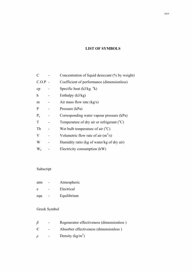
LIST OF SYMBOLS
C - Concentration of liquid desiccant (% by weight)
C.O.P - Coefficient of performance (dimensionless)
cp - Specific heat (kJ/kg. ok)
h - Enthalpy (kJ/kg)
m - Air mass flow rate (kg/s)
P - Pressure (kPa)
Pe - Corresponding water vapour pressure (kPa)
T - Temperature of dry air or refrigerant (oC)
Tb - Wet bulb temperature of air (oC)
V - Volumetric flow rate of air (m3/s)
W - Humidity ratio (kg of water/kg of dry air)
We - Electricity consumption (kW)
Subscript
atm - Atmospheric
e - Electrical
equ - Equilibrium
Greek Symbol
β - Regenerator effectiveness (dimensionless )
Є - Absorber effectiveness (dimensionless )
ρ - Density (kg/m3)
xxvi
LIST OF APPENDICES
APPENDIX TITLE PAGE
1 Standard specification of thermocouple changeover
Switch (RS-506-E) 155
2 Standard specification of an electronic temperature
Indicator (RIN-500) 156
3 Results of effect of liquid desiccant flow rate
and air flow rate 157
4 Absorber effectiveness 160
5 Regenerator effectiveness 162
6 Publications 164
CHAPTER 1
INTRODUCTION
1.1 Background
The 1990s and 1980s were challenging decades for the Heating, Ventilation
and Air- Conditioning (HVAC) industry. The need for ever more efficient heating,
cooling, ventilation and dehumidification technologies was more urgent than during
the energy crisis of the 1970s. Energy resources were more depleted and the energy
demands of a growing global population continued to increase with the increase in
the demand for comfort cooling even in the developing countries, due to the present
modernisation. Mankind are continuously endeavouring to improve their
surroundings and make the working and residential environment more comfortable
and healthy to the human beings. Started with the first fire set at the mouth of a
cave, people have created heating systems to remain comfortable when outside
conditions turn cold. However, only within the last century has mechanical cooling
equipment been used to provide comfort in buildings. Comfort in buildings can be
more than a luxury; a recent study by Rensselaer Polytechnic Institute suggests that
comfortable working environment can lead to a 2% improvement in job performance
(Bobenhausen, W. 1994). Furthermore is the reduction in absentees due to a
reduction in Sick Building Syndrome (S.B.S.).
The introduction of the ASHRAE code to increase the ventilation air
requirement in building so as to improve Indoor Air Quality (IAQ), “ASHRAE -
Standard 62-1989 Minimum ventilation rates for acceptable indoor air quality” even
2
makes the situation worse for conventional air conditioning equipment. Their
capacities need to be increased to accommodate the newly imposed loads. However,
with the increased efficiency of the vapour compression equipment the additional
sensible load can be easily handled. But the additional latent load is the remaining
problem bearing in mind that the ventilation air contributes about 60% of the
principal source of moisture load especially in commercial buildings (Harriman, L.
G. et al 1999) that adds to the latent load required to be removed.
Traditionally air conditioning has been achieved by vapour compression
equipment, that are usually very efficient in handling air conditioning load which is
characterised by high sensible heat ratio. These equipment performed poorly when a
situation of low sensible heat ratio arises (high latent heat ratio). In this case they use
the technique of lowering the dew point temperature of the process air to a degree
that satisfies the latent heat load removal by condensing the water vapour out of the
process air. This dew point temperature will be below the desired temperature level,
then reheat or if possible mixing with the re-circulating air to bring the supply air
temperature to the desired level. This process of sub-cooling followed by reheat is
an energy consuming process which increase the operational costs as well as the
capital cost due to the purchase of the reheat equipment.
1.2 Global Warming and Refrigerants
The development of more efficient HVAC technology is much constrained
now than it was 30 years ago. In recent years, ozone layer depletion and greenhouse
effect have created considerable public concern. The fully halogenated
chloroflourocarbons “CFCs” which have provided much needed refrigeration and
air-conditioning for about 60 years, are among the gases responsible for the depletion
of ozone layer, and for creating global warming. These CFCs must be phased out by
now, but in fact they are still being produced and about 65 % produced annually are
being used only to replace the leaked out CFCs and the remaining 35 % are used in
manufacturing new refrigerators, air-conditioners and other cooling appliances.
Knowing that these CFCs have an average lifetime of 100 years in the atmosphere
3
and today’s emission will continue to affect the ozone layer for another century or so,
one can realise how it is important to find other refrigerants or other methods for
cooling that did reduce the use of the refrigerant while meeting the same cooling
load. This leads to a considerable research for new refrigerants and the adaptation of
the existing machinery to the alternative refrigerant. Also efforts have been devoted
to the development of alternative methods of refrigeration and air-conditioning and
one of these alternative methods is desiccant cooling.
It is unlikely that a single cooling and dehumidification technology will
emerge as the perfect solution to today’s CFCs /HCFCs systems in all applications.
And in order to find a solution to this situation, designers, owners, and manufactures
have to examine other options or systems that can solve this to eliminate or reduce
the emission of these CFCs / HCFCs, independently or by integration with the
conventional methods. One of the most attractive option is the desiccant based
cooling system. Desiccants are materials that have strong affinity for water, they
adsorb/ absorb water from the air when brought into direct contact with them, hence,
the air become drier and warmer and requires to be cooled by other conventional
method before being delivered into the conditioned space. The desiccant becomes
saturated or diluted after adsorbing/ absorbing the moisture from the air, and needs to
be regenerated by adding heat to drive-off the adsorbed/ absorbed moisture. Any
integration of desiccant based cooling system with the vapour compression system
will result in a hybrid system, which will benefit from the characteristics of both
systems (vapour compression system is very efficient in handling the sensible load,
while the desiccant system has the superiority of handling the latent load effectively)
and hence, separating the load between them. This also results in high coefficient of
performance of the vapour compression system, because it’s evaporator will work at
higher temperature, making the size of the unit to be used smaller.
1.3 Market Forces
In the late 1980s a number of market forces accelerate the demand for
desiccant based cooling system equipment, these forces are:
4
(i) Indoor Air Quality (IAQ):
The application of new ASHRAE standard (ANSI/ASHRAE
STANDARD 62-1989, Ventilation for acceptable indoor air quality)
to address the IAQ problems, increased the ventilation air on average
from 5 cfm per person to 15-20 cfm per person, increasing the latent
load fraction that the HVAC system should handle (McGahey,
K.1998).
(ii) Demand for comfort:
Controlling the humidity level has shown a great effect on some air
conditioning application economics, typical applications are hotels,
hospitals, clean rooms (McGahey, K.1998).
(iii) New economics of air conditioning:
The economic cost involved in some applications that require tight
control of humidity accelerated the implementation of desiccant based
cooling system to address the high cost in such applications, typical
applications are museums, libraries, and others (McGahey, K.1998).
1.4 Problem Statement
Desiccant systems (solid and liquid) are available for around 30 years or so,
but surprisingly their full potential is yet to be realised. Part of that is due to the
precedence that they can only be used in special applications mainly in industrial
process and industrial air conditioning which resulted in a lack of knowledge within
the Heating, Ventilating, and Air Conditioning (HVAC) engineers about their
potential applications in the area of residential and commercial air conditioning,
especially when integrated with other technologies. Questions like the following
have to be answered:
5
i) How can these systems be operated to achieve their optimal working
conditions (with emphasis on liquid desiccant)?
ii) What are the main components of the liquid desiccant system that need
special consideration to help achieve such goal?
iii) What is the benefit of using liquid desiccant in the air conditioning field and
how they can be integrated with the most common technology like vapour
compression equipment?
iv) What kind of improvement is expected from such proposed system?
Vapour compression units are well known for their superiority in the
applications characterised with or dominated with higher sensible load fractions, and
the desiccants are known for their ability to tackle humid air and they are superior in
terms of dehumidification compared to the vapour compression. Based on these
facts the proposed hybrid system consisting of vapour compression unit and a liquid
desiccant sub-system may offer better performance and have to be proven
practically, hence the research problem/hypothesis can be formulated as:
“What a hybrid liquid desiccant cooling system would offer in terms of
improvement in the performance, and what are the optimal working conditions for
the liquid desiccant sub-system in order to achieve such improved performance in
terms of coefficient of performance and better humidity control”.
1.5 Research Scope
The scope of this research is to study of a hybrid desiccant based cooling
system. This system containing vapour compression system is integrated with a
liquid desiccant system and a flat plate solar hot water collector. Development of the
system and testing its performance and operational potential is undertaken to reduce
the use of the conventional air conditioning methods with more emphasis on the
6
liquid desiccant sub-system. Different liquid desiccant system arrangement and
different modes of operation will be studied to find the optimal system configuration
and hence to determine the available and economical method for regeneration (solar
energy, waste heat reclaim) that is to be used to obtain improvement in the system
coefficient of performance. Also the effect of liquid desiccant on the coefficient of
performance of the vapour compression unit will be studied.
1.6 Research Objectives
The objectives of the research can be summarised in the following points:
i. To determine the effect of liquid desiccant-based cooling system on the
performance of the vapour compression system when both systems are
integrated together (hybrid system).
ii To determine the working condition for the absorber and the regenerator of
the liquid desiccant sub-system.
iii To determine the methods and options of regeneration process (solar energy,
waste heat recovery) and selecting the proper option to reduce energy
consumption and hence reduce the system operating cost.
iv To determine the improvement in the coefficient of performance of the
vapour compression unit when it works at higher evaporator temperature.
1.7 Thesis Outline
Chapter Two covers the literature review and work done in the field
of desiccant application in the air-conditioning field. Solar cooling and solar energy
usage related to the same field are also given in Chapter Two with applications in
7
regeneration of desiccant materials with more emphasis on applications in liquid
desiccant regeneration
Chapter Three gives the theoretical framework of different air-conditioning
cycles and systems, mainly the vapour compression cycle and the desiccant systems,
and the principles of how desiccant sub-system works when integrated with the
above mentioned cycle. More theory about what desiccant materials are and how
they work, their cycle, and their classifications are also explained.
Chapter Four is devoted to the methodology and system configuration and the
setting of the testing facility with full description. Data logging system and its
features and limitations are also given. Independent and dependent variables and all
measurable values with details of how these measurements were conducted are fully
explained.
Chapter Five deals with the results and calculations carried out with the
discussion given. Also Absorber effectiveness and regenerator effectiveness were
calculated and discussed and the benefits from using desiccant sub-system are given.
Conclusions and recommendations for future work are discussed in Chapter
Six.
REFERENCES
Abdul Wahab, S. A., Zurigat, Y. H., and Abu-Arabi, M. K. (2004). Prediction of
Moisture Removal Rate and Dehumidification Effectiveness for Structured
Liquid Desiccant Air Dehumidifier. Energy: 19-34.
Albers, W. F., Beckman, J. R., Farmer, R. W., and Gee, K. G. (1991). Ambient
Pressure, Liquid Desiccant Air Conditioner. ASHRAE Transactions. 97 (2):
603-608.
ASHRAE. (1993). Sorbents and Desiccants. In: ASHRAE Handbook-Fundamentals,
American Society of Heating, Refrigerating, and Air- Conditioning Engineers
Inc.: Atlanta, USA.
ASHRAE. (1985). Sorbents and Desiccants. In: ASHRAE Handbook-Fundamentals.
American Society of Heating, Refrigerating, and Air- Conditioning
Engineers, Inc.: Atlanta, USA.
ASHRAE. (1977). Sorbents and Desiccants. In ASHRAE Handbook-Fundamentals.
American Society of Heating, Refrigerating, and Air- Conditioning
Engineers, Inc.: Atlanta, USA.
ASHRAE. (1979). Sorption Dehumidification and Pressure Drying Equipment. In:
ASHRAE Handbook-Fundamentals. American Society of Heating,
Refrigerating, and Air-conditioning Engineers, Inc.: Atlanta, USA.
149
Badawi, E. M. (1998) Properties and Performance Characteristics of Liquid
Desiccant. Universiti Teknologi Malaysia: Master of Engineering. Thesis.
Banks, N. J. (1990). Desiccant Dehumidifiers in Ice Arena. ASHRAE Transactions.
96 (1): 1269-1272.
Banks, N. J. (1992). Field Test of a Desiccant-Based HVAC System for Hotels.
ASHRAE Transactions. 98 (1): 1303-1310.
Bobenhausen, W. (1994). Simplified Design of HVAC Systems. New York, U.S.A:
John Wiley & Sons Inc.
Burns, P. R. , Mitchell, J. W. , and Beckman, W. A. (1985). Hybrid Desiccant
Cooling Systems in Supermarket Applications. ASHRAE Transactions. 91
(1B): 457-467.
Chung, W. T., Ghosh, T. K., Hines, A. L. and Novosel, D. (1993) Removal of
Selected Pollutants From Air During Dehumidification By Lithium Chloride
And Triethylene Glycol Solutions. ASHRAE Transactions. 99: 834-841.
Collier, R. K. and Cohn, B. M. (1991). An Analytical Examination of Methods for
Improving The Performance of Desiccant Cooling Systems. Journal of Solar
Energy Engineering. 113: 157-163.
Cohn, B. M. and Slosberg, R. B. (1988). “Application of Gas-Fired Desiccant
Cooling Systems” ASHRAE Transactions, 94 (1); 525-536.
Dai, Y. J., Wang, R.Z., Zhang, H. F., and Yu, J.D. (2001). Use of Liquid Desiccant
Cooling to Improve The Performance of Vapor Compression Air
Conditioning. Applied Thermal Engineering. 21: 1185-1202.
Dhar,P. L., Kaushik, S. C., Jain, S., Pahwa, D., and Kumar, R. (1995).
Thermodynamic Analysis of Desiccant Augmented Evaporative Cooling
Cycles for Indian Conditions. ASHRAE Transactions. 101 (1): 735-749.
150
Gandhidasan, P. (1984). Comparative Study of Two Types of Solar Regenerators for
Liquid Absorption Dehumidification System. ASHRAE Transactions. 90
(2A): 78-84.
Gandhidasan, P. (1983). Theoretical Study of Tilted Solar Still as a Regenerator for
Liquid Desiccants. Energy Convers. Mgmt. 23 (2): 97-101.
Goswami, D. Y. ,Ek, G. , Leung, M. , Jotshi, C. K., and Sherif, S. A. (2001). Effect
of Refrigerant Charge on the Performance of Air conditioning Systems.
Interntional Journal of Energy Research. 25: 741-750.
Halliday, S. P., Beggs, C. B., and Sleigh, P. A. (2002). The Use of Solar Desiccant
Cooling in The UK: A Feasibility Study. Applied Thermal Engineering. 22:
1327-1338.
Harriman, L. G., Czachorski, M., Witte, M. J., and Kosar, D. (1999). Evaluating
Active Desiccant Systems For Ventilating Commercial Buildings. ASHRAE
Journal. 42 (10): 28-37.
Henning, H-M., Erpenbeck, T., Hindenburg, C., and Santamaria, I. S. (2001). The
Potential of Solar Energy Use in Desiccant Cooling Cycles. International
Journal of Refrigeration. 24: 220-229.
Hollands, K. G. T. (1963). The regeneration of Lithium Chloride Brine in a Solar
Still. Solar Energy. 7 (2): 39-43.
Jain, S., Dhar, P. L., and Kaushik, S. C. (1995). Evaluation of Solid Desiccant-Based
Evaporative Cycles for Typical Hot-Humid Climates. International Journal
of Refrigeration. 18 (5); 287-296.
Jain, S., Dhar, P. L., and Kaushik, S. C. (2000). Experimental Studies on The
Dehumidifier and Regenerator of a Liquid Desiccant Cooling System.
Applied Thermal Engineering. 0: 253-267.
151
Joudi, K. A. and Madhi, S. M. (1987). An Experimental Investigation into a Solar
Assisted Desiccant-Evaporative Air Conditioning System. Journal of Solar
Energy. 39 (2): 97-107.
Joudi, K. A. and Dhaidan, N. S. (2001). Application of Solar Assisted Heating and
Desiccant Cooling Systems for A Domestic Building. Energy Convers. And
Management. 42: 995-1022.
Kosar, D. (1990). Desiccant Dryers. In Handbook of HVAC Design. edited by
Grimm, N. R. and Rosaler, R. C: R. R. Donnelley and Sons company. : U. S.
A.
Lof, G. O., Cler, G., and Brishane, T. (1988). Performance of a Solar Desiccant
Cooling System. Journal of Solar Energy Engineering. 110: 165-171.
Lowenstein, A., and Novosel, D. (1995). The Seasonal Performance of a Liquid-
Desiccant Air Conditioner. ASHRAE Transactions. 101 (1): 679-685.
Lowenstein, A. and Dean, M. H. (1992). The Effect of Regenerator Performance on a
Liquid-Desiccant Air Conditioner. ASHRAE Transactions. 98 (1): 704-711.
Lu, S. M., and Yan, W. J. (1995). Development and Experimental Validation of A
Full-Scale Solar Desiccant Enhanced Radiative Cooling System. Renewable
Energy. 6 (7): 821-827.
Maclaine-Cross, I. L. (1988). Proposal for a Hybrid Desiccant Air Conditioning
System. ASHRAE Transactions. 94 (2): 1997-2009.
Manley, D. L., Bowlen, K. L. and Cohen, B. M. (1985). Evaluations of Gas-Fired
Desiccant-Based Space Conditioning for Supermarkets. ASHRAE
Transactions. 91 (1B): 447-456.
152
Marciniak, T. J., Koopman, R. N., and Kosar, D. R. (1991). Gas-Fired Desiccant
Dehumidification System in a Quick-Service Restaurant. ASHRAE
Transactions. 97 (1): 657-666.
Marsala, J., Lowenstein, A., and Ryan, W. A. (1989). Liquid Desiccant for
Residential Applications. ASHRAE Transactions. 95 (1): 828-835.
Mavroudaki, P., Beggs, C. B., Sleigh, P. A., and Halliday, S. P. (2002). The Potential
For Solar Powered Single-Stage Desiccant Cooling in Southern Europe.
Applied Thermal Engineering. 22: 1129-1140.
McGahey, K. (1998). New Commercial Applications For Desiccant-Based Cooling.
ASHRAE Journal. 40 (7): 41-45.
McQuiston, F. C. and Parker, J. D. (1994) Heating, Ventilation, and Air
Conditioning: Analysis and Design. 4th edition. U. S. A.: Jone Wiley and Sons
Ins.
Meckler, G. (1990). Use of Desiccant to Produce Cold Air in Gas-Energized Cold-
Air HVAC System. ASHRAE Transactions.96 (1): 1257-1261.
Meckler, G. (1991). Comparative Energy Analysis of Gas-Energized Desiccant
Cold-Air Unit. ASHRAE Transactions. 97 (1): 637-641.
Meckler, M. (1989). Integrated Desiccant Cold Air Distribution System. ASHRAE
Transactions. 95 (2): 1085-1097.
Oliveira, A. C., Alfonso, C. F., Riffat, S. B., and Doherty, P. S. (2000). Thermal
Performance of A Novel Air-Conditioning System Using A Liquid Desiccant.
Applied Thermal Engineering. 20: 1213-1223.
Parsons, B. K., Persaran, A. A., Bharathan, D., and Shelpuk, B. (1989). Improving
Gas-Fired Heat Pump Capacity and Performance by Adding a Desiccant
Dehumidification Subsystem. ASHRAE Transactions. 95 (1): 835-843.
153
Peng, C. S. P. and Howell, J. R. (1984). The Performance of Various Types of
Regenerators for Liquid Desiccants. Journal of Solar Energy Engineering.
106: 133-141.
Pesaran, A. A., Parent, Y. O., Meckler, M., and Novosel, D. (1995). Evaluation of a
Liquid Desiccant-Enhanced Heat Pipe Air Conditioner. ASHRAE
Transactions. 101 (1): 713-724.
Stoecker, W. F. and Jones, J. W. (1982). Refrigeration and Air Conditioning.
2ndedition. Singapore: McGraw-Hill Book Co.
Subramanyam, N., Maiya, M. P., Srinivasa Murthy, S. (2004). Parametric Studies on
A Desiccant Assisted Air-Conditioner. Applied Thermal Engineering. 24:
2679-2688.
Toh, K. C., Chan, S. K., and Chu, H. H. (1989). Simulation of a Solar-Assisted,
Desiccant-Based Air Conditioning System Under Singapore Weather
Conditions. In Proceedings of Far East Conference on Air Conditioning in
Hot Climates. Kuala Lumpur, Malaysia 67-70.
Turner, R. H., Kleiser, J. D., Chen, R. F., Domingo, N., and Chen, F. (1988).
Assessment of Thermally Activated Heat Pumps With Desiccant Cooling.
ASHRAE Transactions. 94 (1): 552-562.
West, M. K. and Iyer, S. V. (1995). Analysis of a Field-Installed Hybrid Solar
Desiccant Cooling System. ASHRAE Transactions. 101 (1): 686-696.
Wilkinson, W. H. (1988a). Liquid Desiccant Hybrid Complexity Made Simple.
ASHRAE Transactions. 94 (2): 2010-2023.
Wilkinson, W. H., Landstrom, D. K., and Novosel, D. (1988b). Dublsorb-A
Universal Desiccant Hybrid Approach. ASHRAE Transactions. 94 (1): 563-
574.
154
Wilkinson, W. H. (1990). Alternative Dublsorb Concepts. ASHRAE Transactions. 96
(1): 1273-1279.
Wilkinson, W. H. (1991). Evaporative Cooling Trade-offs in Liquid Desiccant
Systems. ASHRAE Transactions. 97 (1): 642-649.
Worek, W. M. (1988). Desiccant Integrated Hybrid Vapour Compression Cooling:
Performance Sensitivity To Outdoor Conditions. Heat Recovery Systems &
CHP. 8 (6): 489-501.
Yang, K. H. (1989). Analysis of a Solar-Assisted Desiccant Dehumidification
System in Subtropical Weather. In Proceedings of Far East Conference on
Air Conditioning in Hot Climates. Kuala Lumpur, Malaysia: 123-127.
Yadav, Y. K. (1995). Vapour-Compression and Liquid Desiccant Solar Space-
Conditioning System for Energy Conservation. Renewable Energy. 6 (7):
719-723.
Zhang, L.Z. and Niu, J. L. (2003). A Pre-Cooling Munters Environmental Control
Cycle in Combination with Chilled-Ceiling Panels. Energy. 28: 275-292.
Zhang, X. J., Dai, Y. J., and Wang, R. Z. (2003). A Simulation Study of Heat and
Mass Transfer in A Honeycombed Rotary Desiccant Dehumidifier. Applied
Thermal Engineering. 23: 989-1003.