
Buletin GIS & GEOMATIK · Accuracy Assessment Procedure for Aerodrome Charts for ICAO’S Universal...
60
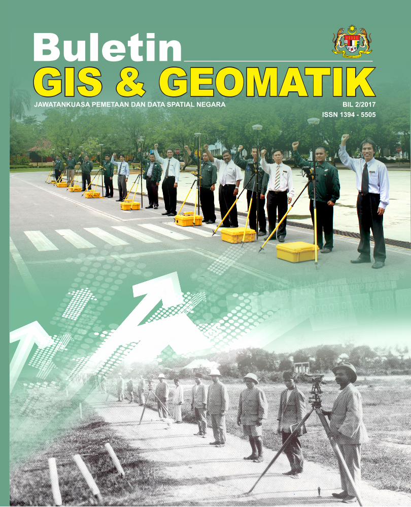
i GIS & GEOMATIK Buletin BIL 2/2017 ISSN 1394 - 5505 JAWATANKUASA PEMETAAN DAN DATA SPATIAL NEGARA
Transcript of Buletin GIS & GEOMATIK · Accuracy Assessment Procedure for Aerodrome Charts for ICAO’S Universal...
i
GIS & GEOMATIKBuletin
BIL 2/2017ISSN 1394 - 5505
JAWATANKUASA PEMETAAN DAN DATA SPATIAL NEGARA

Jemaah Menteri berasaskan Kertas Kabinet No.243/385/65 bertajuk National Mapping Malaysia telah meluluskan jawatan dan terma-terma rujukan “Surveyor-General Malaya and Singapore” sebagai Pengarah Pemetaan Negara Malaysia dan mengesahkan keanggotaan serta terma-terma rujukan Jawatankuasa Pemetaan Negara pada 31 Mac 1965. Cabutan para-para 2(b), 2(c) dan 2(d) daripada kertas kabinet tersebut mengenai keanggotaan dan terma-terma rujukannya adalah seperti berikut: “2(b) National Mapping Committee
That a National Mapping Committee be appointed to comprise the following:
i. Director of National Mapping ii. Director of Lands & Surveys, Sabah; iii. Director of Lands & Surveys Sarawak; iv. Representative of the Ministry of Defence; v. Representative of the Ministry of Rural Development (now substituted by the Ministry of Natural
Resources and Environment); vi. Assistant Director of Survey, FARELF
2(c) The terms of reference of the National Mapping Committee to be as follows:
i. to advise the Director of National Mapping on matters relating to mapping policy; ii. to advise the Director of National Mapping on mapping priorities.
2(d) That the Committee be empowered to appoint a Secretary and to co-opt persons who would be
required to assist the Committee,” Seterusnya pada 22 Januari 1997, Jemaah Menteri telah meluluskan pindaan terhadap nama, keanggotaan dan bidang-bidang rujukan Jawatankuasa Pemetaan Negara kepada Jawatankuasa Pemetaan dan Data Spatial Negara (JPDSN), bagi mencerminkan peranannya yang diperluaskan ke bidang data pemetaan berdigit. Keanggotaan JPDSN pada masa kini adalah terdiri daripada agensi-agensi seperti berikut:
Buletin GIS dan Geomatik ini yang diterbitkan dua kali setahun adalah merupakan salah satu aktiviti oleh Jawatankuasa Pemetaan dan Data Spatial Negara, sebagai salah satu media pendidikan dan penyebaran maklumat dalam mendidik masyarakat memanfaatkan maklumat spatial dalam pembangunan negara. Walau bagaimanapun, sebarang kandungan artikel-artikel adalah tanggungjawab penulis sepenuhnya dan bukan melambangkan pandangan penerbit.
PENDAHULUAN
1. Jabatan Ukur dan Pemetaan Malaysia 11. Jabatan Pertanian Sarawak 2. Jabatan Tanah dan Ukur Sabah 12. Agensi Remote Sensing Malaysia (ARSM) 3. Jabatan Tanah dan Survei Sarawak 13. Universiti Teknologi Malaysia 4. Wakil Kementerian Pertahanan 14. Universiti Teknologi MARA (co-opted) 5. Jabatan Mineral dan Geosains Malaysia 15. Universiti Sains Malaysia (co-opted) 6. Jabatan Perhutanan Semenanjung Malaysia 16. Jabatan Laut Sarawak (co-opted) 7. Jabatan Pertanian Semenanjung Malaysia 17. Jabatan Perhutanan Sarawak 8. Jabatan Perhutanan Sabah 18. PLANMalaysia Semenanjung Malaysia (co-opted) 9. Pusat Infrastruktur Data Geospatial Negara
(MaCGDI) (co-opted) 19. Jabatan Pengairan dan Saliran (JPS)
10. Jabatan Pertanian Sabah
PENDAHULUAN
Penaung
YBhg. Dato’ Sr Mohd Noor bin IsaKetua Pengarah Ukur dan Pemetaan Malaysia
Penasihat
Sr Ahamad bin Zakaria, KMN, FRISMPengarah Ukur Bahagian(Dasar dan Penyelarasan Pemetaan)
Ketua Editor
Sr Zulkifli bin SidekPengarah Ukur Seksyen(Dasar Pemetaan)
Editor
Sr Zainal Abidin bin Mat ZainSr Mohd Riduan bin Mohamad @ IdrisSr Nur Akma binti SaharuddinNoor Haslinda binti Mohamed YusopSiti Norazin binti Mat Lazi
Susunan dan Rekabentuk Tn. Hj. Hanin bin Hashim, AMNNaiemah binti Dahari
Pencetak
Jabatan Ukur danPemetaan Malaysia,Jalan Sultan Yahya Petra,50578 Kuala Lumpur
Nota: Kandungan yang tersiar boleh diterbitkan semula dengan izin Urus Setia
Jawatankuasa Pemetaan dan Data Spatial Negara.
Kandungan
Dari Meja Ketua Editor......................................................................................................................................................... i
Accuracy Assessment Procedure for Aerodrome Charts for ICAO’S Universal Safety Oversight Audit Program (USOAP) Continuous Monitoring Approach (CMA) for Protocol Question (PQ) 7.359Mohd Fazly Bin Mohd Noor......…………………….…...................................................................................................... 1
Zon-Zon Sempadan Maritim Berpandukan Kepada Konvensyen Undang-Undang Laut 1982 (KUUL 1982)Sr Zakaria Abdullah.........................................................……………................................................................................ 24
The Development of Marine Geodetic Infrastructures in East Malaysia Waters (2013 – 2017)Dr. Sr Azhari Bin Mohamed, Sr Sohaime Bin Hj Rasidi, Sr Zulkafli Bin Chihat, Sr Shabudin Bin Saad, Dato’ Dr. Abd Majid A Kadir, Ahmad Fahmi Bin Abd Majid, Syarifuddin Bin Mat Zali, Assoc. Prof. Dr. Kamaludin Talib, Dr. Saiful Aman Bin Sulaiman……….......………….....…....................................... 30
Laporan Bergambar: Laporan The 6th Plenary Meeting Of United Nations Global Geospatial Information Management For Asia And The Pacific (UN-GGIM-AP) Kumamoto, JepunSr Mohd Riduan bin Mohamad @ Idris….……...………...………................................................................................... 46
Mesyuarat Ke-19 Jawatankuasa Teknikal Nama Geografi Kebangsaan (JTNGK)Sr Zainal Abidin bin Mat Zain............................................................................................................................................ 48
Mesyuarat Jawatankuasa Penyelaras Penggambaran Dan Pengimejan Udara Bagi Agensi-Agensi Di Bawah NRE (JPPPNRE) Bil. 2/2017Sr Mohd Riduan bin Mohamad @ Idris….……...………...………................................................................................... 52
Kalendar GIS 2018............................................................................................................................................................. 54
Sumbangan Artikel/Call for Paper……………………………………………………………………………………............. 55
Sidang Pengarang
Jemaah Menteri berasaskan Kertas Kabinet No.243/385/65 bertajuk National Mapping Malaysia telah meluluskan jawatan dan terma-terma rujukan “Surveyor-General Malaya and Singapore” sebagai Pengarah Pemetaan Negara Malaysia dan mengesahkan keanggotaan serta terma-terma rujukan Jawatankuasa Pemetaan Negara pada 31 Mac 1965. Cabutan para-para 2(b), 2(c) dan 2(d) daripada kertas kabinet tersebut mengenai keanggotaan dan terma-terma rujukannya adalah seperti berikut: “2(b) National Mapping Committee
That a National Mapping Committee be appointed to comprise the following:
i. Director of National Mapping ii. Director of Lands & Surveys, Sabah; iii. Director of Lands & Surveys Sarawak; iv. Representative of the Ministry of Defence; v. Representative of the Ministry of Rural Development (now substituted by the Ministry of Natural
Resources and Environment); vi. Assistant Director of Survey, FARELF
2(c) The terms of reference of the National Mapping Committee to be as follows:
i. to advise the Director of National Mapping on matters relating to mapping policy; ii. to advise the Director of National Mapping on mapping priorities.
2(d) That the Committee be empowered to appoint a Secretary and to co-opt persons who would be
required to assist the Committee,” Seterusnya pada 22 Januari 1997, Jemaah Menteri telah meluluskan pindaan terhadap nama, keanggotaan dan bidang-bidang rujukan Jawatankuasa Pemetaan Negara kepada Jawatankuasa Pemetaan dan Data Spatial Negara (JPDSN), bagi mencerminkan peranannya yang diperluaskan ke bidang data pemetaan berdigit. Keanggotaan JPDSN pada masa kini adalah terdiri daripada agensi-agensi seperti berikut:
Buletin GIS dan Geomatik ini yang diterbitkan dua kali setahun adalah merupakan salah satu aktiviti oleh Jawatankuasa Pemetaan dan Data Spatial Negara, sebagai salah satu media pendidikan dan penyebaran maklumat dalam mendidik masyarakat memanfaatkan maklumat spatial dalam pembangunan negara. Walau bagaimanapun, sebarang kandungan artikel-artikel adalah tanggungjawab penulis sepenuhnya dan bukan melambangkan pandangan penerbit.
PENDAHULUAN
1. Jabatan Ukur dan Pemetaan Malaysia 11. Jabatan Pertanian Sarawak 2. Jabatan Tanah dan Ukur Sabah 12. Agensi Remote Sensing Malaysia (ARSM) 3. Jabatan Tanah dan Survei Sarawak 13. Universiti Teknologi Malaysia 4. Wakil Kementerian Pertahanan 14. Universiti Teknologi MARA (co-opted) 5. Jabatan Mineral dan Geosains Malaysia 15. Universiti Sains Malaysia (co-opted) 6. Jabatan Perhutanan Semenanjung Malaysia 16. Jabatan Laut Sarawak (co-opted) 7. Jabatan Pertanian Semenanjung Malaysia 17. Jabatan Perhutanan Sarawak 8. Jabatan Perhutanan Sabah 18. PLANMalaysia Semenanjung Malaysia (co-opted) 9. Pusat Infrastruktur Data Geospatial Negara
(MaCGDI) (co-opted) 19. Jabatan Pengairan dan Saliran (JPS)
10. Jabatan Pertanian Sabah
Dari Meja Ketua Editor
i
Assalamualaikum WBT dan Salam 1 MalaysiaSidang Pengarang Buletin GIS dan Geomatik Bil.2/2017 terlebih dahulu mengucapkan tahniah kepada YBhg. Dato’ Sr Mohd Noor bin Isa, di atas pelantikkan sebagai Ketua Pengarah Ukur dan Pemetaan Malaysia (KPUP) merangkap pengerusi Jawatankuasa Pemetaan dan Data Spatial Negara (JPDSN) pada 21 Ogos 2017.
Perkongsian maklumat geospatial adalah amat penting dalam menyelesaikan pelbagai masalah dan isu diperingkat nasional dan global yang antara lainnya adalah dalam pengurusan bencana. Dalam mesyuarat ke-6 United Nations Global Geospatial Management for Asia and the Pacific (UN-GGIM-AP) yang telah diadakan pada 16 – 19 Oktober 2017 di Kumamoto, Jepun telah diadakan satu sesi khas bagi membincangkan peranan dan aktiviti-aktiviti yang telah dan boleh dijalankan oleh agensi-agensi yang berkaitan dengan maklumat geospatial bagi setiap negara ahli dalam membantu menangani kejadian sesuatu bencana. Objektif sesi khas ini adalah untuk mendapatkan input dalam menghasilkan satu garis panduan yang terbaik dalam membantu negara ahli dalam melakukan tindakan dalam menghadapi sesuatu kejadian bencana dengan menggunakan maklumat geospatial.
Berdasarkan kepentingan maklumat geospatial dalam pelbagai perkara termasuk perancangan dan pengurusan maka ketersediaan maklumat geospatial yang terkini dan tepat adalah amat penting. Justeru itu, bagi memastikan maklumat geospatial JUPEM sentiasa dikemaskini dengan mengambilkira penjimatan kos maka berpegangkan prinsip ‘collect once use by many’, Jabatan Ukur dan Pemetaan Malaysia (JUPEM) terus mempergiatkan usaha untuk perlaksanaan NBOS bersama dengan agensi-agensi kerajaan termasuklah Pihak Berkuasa Tempatan (PBT). Dalam usaha untuk mempercepatkan pengemaskian maklumat geospatial, jalinan sebegini amat perlu kerana Pihak Berkuasa Tempatan (PBT) boleh dijadikan sebagai penyumbang maklumat bermula dari peringkat arahan merancang lagi.
Pendedahan kepada masyarakat secara langsung juga adalah amat penting dalam menyampaikan peranan dan sumbangan kita sebagai agensi-agensi yang mengurus dan menyediakan maklumat geospatial dalam pembangunan negara dan kesejahteraan rakyat. Sehubungan dengan itu, satu program ‘outreach’ yang dinamakan sebagai program Ukur Bersama Rakyat atau UBeR telah dirancang untuk diadakan pada bulan 9 – 10 Mac 2018 bertempat di Daerah Tangkak, Johor Darul Takzim. Seluruh warga Tangkak dan sekitarnya adalah dijemput untuk turut serta memeriahkan program ini.
Seperti yang kita sedia maklum, Buletin GIS dan Geomatik ini merupakan wadah yang disediakan untuk warga GIS dan Geomatik berkongsi maklumat dan teknologi terkini berkaitan aktiviti GIS dan Geomatik. Sidang pengarang menyeru agar mana-mana pihak yang terlibat dalam bidang GIS dan Geomatik menyumbangkan sebarang bentuk hasil kajian atau aktiviti untuk dimuatkan dalam Buletin GIS dan Geomatik bagi edisi-edisi yang seterusnya.
1
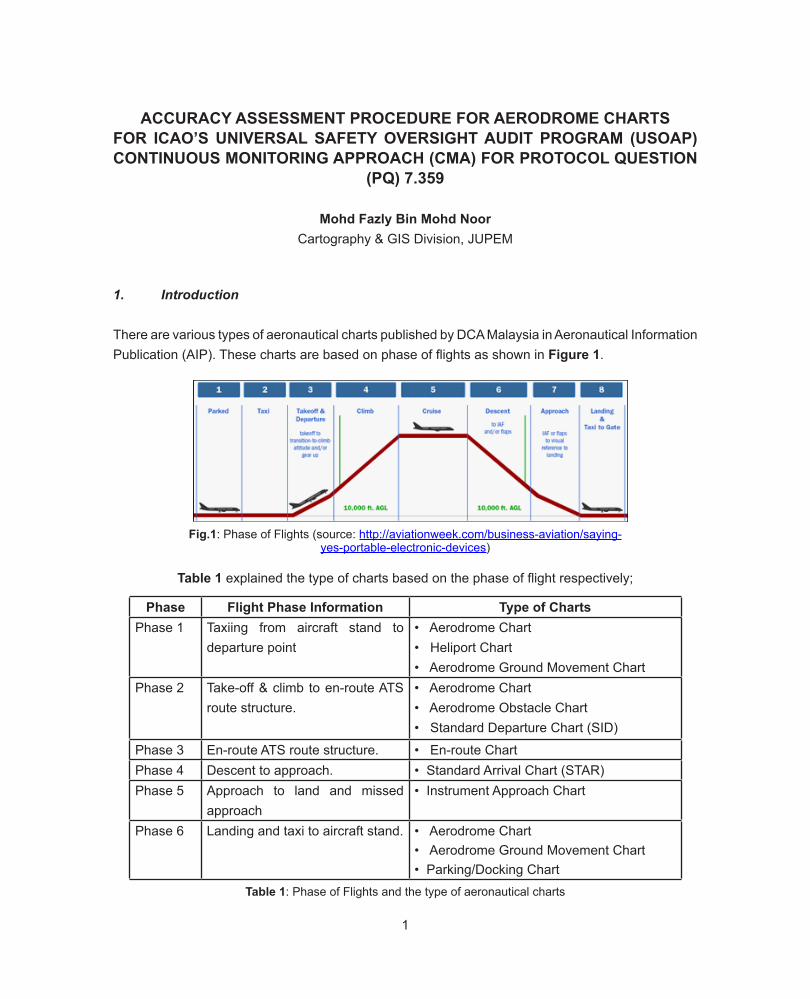
ACCURACY ASSESSMENT PROCEDURE FOR AERODROME CHARTS FOR ICAO’S UNIVERSAL SAFETY OVERSIGHT AUDIT PROGRAM (USOAP) CONTINUOUS MONITORING APPROACH (CMA) FOR PROTOCOL QUESTION
(PQ) 7.359
Mohd Fazly Bin Mohd NoorCartography & GIS Division, JUPEM
1. Introduction
There are various types of aeronautical charts published by DCA Malaysia in Aeronautical Information Publication (AIP). These charts are based on phase of flights as shown in Figure 1.
Fig.1: Phase of Flights (source: http://aviationweek.com/business-aviation/saying-yes-portable-electronic-devices)
Table 1: Phase of Flights and the type of aeronautical charts
Phase Flight Phase Information Type of ChartsPhase 1 Taxiing from aircraft stand to
departure point• Aerodrome Chart• Heliport Chart• Aerodrome Ground Movement Chart
Phase 2 Take-off & climb to en-route ATS route structure.
• Aerodrome Chart• Aerodrome Obstacle Chart• Standard Departure Chart (SID)
Phase 3 En-route ATS route structure. • En-route ChartPhase 4 Descent to approach. • Standard Arrival Chart (STAR)Phase 5 Approach to land and missed
approach• Instrument Approach Chart
Phase 6 Landing and taxi to aircraft stand. • Aerodrome Chart• Aerodrome Ground Movement Chart• Parking/Docking Chart
Table 1 explained the type of charts based on the phase of flight respectively;
2
In January 1999, International Civil Aviation Organization (ICAO) introduced Universal Safety Oversight Audit Program (USOAP) as a response to the global concerns on the adequacy of aviation safety oversight around the world. USOAP activities consisted in regular and mandatory audits of ICAO Member States’ safety oversight systems where Malaysia is one of the signing Members of the ICAO Member States. As a Member States, Malaysia have to follow this program in order to ensure the safety of civil aviation to meet the requirements of the oversight audit program.
Protocol Questions (PQs) are the primary tool developed and utilized in the ICAO Universal Safety Oversight Audit Program (USOAP) Continuous Monitoring Approach (CMA) to assess and evaluate the level of effective implementation of a State’s safety oversight system. These monitoring approaches are based on ICAO Standards and Recommended Practices (SARPs). (USOAP CMA Protocol Questions PEL-1/45 Personnel Licensing and Training — PEL).
States can utilize these PQs to conduct regular self-assessments and internal audits in order to identify and resolve safety deficiencies. From this tool, the States can monitor and assess the health of their aviation system in a proactive ways.
For aeronautical charts, there are 20 PQs in relation of the quality and the integrity of the publishing of the charts. One of the PQs is;
“Has the State established a mechanism to ensure that aeronautical data quality requirements related to the data integrity and charting resolution is in accordance with the provisions of Table 1 to 6 in Appendix 6 of Annex 4?”
Annex 4 is a reference document utilized as guidance in aeronautical charts publishing. This document shows the procedure to produce every type of charts including the standard cartography symbology, the specification of the charts template and the quality of the aeronautical data requirements.
For Aerodrome Chart, ICAO Annex 14 is the reference document for aerodrome design and operations manual.
However, due to there are too many data to be assessed in the single aerodrome charts, only several data are to be considered for assessment which will be discussed further in this article.
2. Aeronautical Data
Malaysia Airport Holding Berhad (MAHB) is the main custodian of the aerodrome data in Malaysia. Other aerodromes such as Senai Airport, Kerteh and Tanjung Manis in Sarawak are managed by Senai Airport Terminal Services (SATS), Petronas and Tanjung Manis Development Sdn. Bhd.

3
There are 39 airports in Malaysia under MAHB supervision consist of 5 international airports, 15 domestic airports and 19 stolports. MAHB are responsible to supervise the producing of Aerodrome Charts, Aerodrome Movement Charts and Aerodrome Parking/Docking Charts. These charts will be presented to DCA for publishing in AIP Malaysia via AIP Amendments and AIP Supplements.
Throughout the years, MAHB has engaged Land Surveying firm to carried-out surveying works in aerodrome area and its perimeter especially for the new airports or if there are any new development or installation and changes within the airport boundary. These charts will be submitted to Airport Standard Division for verification and validation especially on the WGS-84 survey points report.
These changes will be submitted to Air Traffic Management Sector for aeronautical charts producing and publishing works via AIP Supplement and AIP Amendment respectively. The final charts will be published worldwide in Malaysia Aeronautical Information Management System (My-AIMS).
For other aeronautical charts such as Standard Instrument Departure Chart, Standard Arrival Chart and Instrument Approach Chart, the procedure of the charts are designed by Procedure of Air Flight Navigation System and Operations (PANS-OPS) Unit. PANS-OPS Unit utilizing Flight Procedure Design & Airspace Management (FDAM) system to design the flight procedure integrating various sources of data.
All aerodrome data will be presented to the Airport Standard Division and the data will be assessed to ensure it comply with the Annex 14 requirements especially on the Aeronautical Data Quality Requirement as stated in Appendix 5 respectively. Geospatialist will be assisting Airport Standard Division in assessing the accuracy of the surveyed data.
Other chart for Route and Air Defense Exercise (ADEX) and Search & Rescue Exercise (SAREX) are under Airspace Unit, Air Traffic Management Sector supervision.
The accuracy assessment and the quality of the data have to be verified before the data will be presented in the charts. These charts will be submitted to Cartographic Unit via AIS Unit for aeronautical charts preparation. These aeronautical charts will be based upon Annex 4 and Doc 8647 as a main reference in order to fulfill all the requirement sets by ICAO.
4
3. Aeronautical Charts Workflow Processes
A
EDITING/ CORRECTION
PASS
2ND ASSESSMENT Assessment and Validation by
Aviation Cartographer/Geospatialist
Prepare the Final Chart in Pdf Format
Chart’s Preparation by Draughtsman
- Check AIP Supplement or AIP Amendment AIRAC Cycle number.
- Publishing Date.
- Sketches for drafting works - Refer to Annex 4 and ICAO
Charts Sample - Check the chart’s template - Check the text and annotation - Check the placement of the data
AIP AMENDMENT/AIP SUPPLEMENT
Aeronautical Information System (AIS) Unit
Start
Cartographic Unit (AIS/MAP)
Aviation Cartographer/Geospatialist Assessment
Chart’s Final Verification & Validation
5
5
Note: Reference 1. ICAO Annex 4 : Aeronautical Charts 2. ICAO Doc 8697 Aeronautical Charts Manual 3. ICAO Annex 14: Aerodrome Design And
Operations Manual 4. ICAO Annex 15: Aeronautical Information
Services Manual
NO
- Installation of the charts into My-AIMS System
Airport Standard Officer
Head of AIS Unit STU Officers
A
Finish
AIP Malaysia @ eAIP Malaysia Publication
PASS
6
6
4.
Dat
a Q
ualit
y W
orkf
low
Pro
cess
(Ove
rvie
w)
D
ata
Orig
inat
or
Sour
ce o
f Dat
a/D
ata
Orig
inat
or
1.A
erod
rom
e: M
alay
sian
Airp
ort
Hol
ding
Ber
had
(MA
HB
),
Airp
ort S
tand
ard
Div
isio
n
2.In
stru
men
t App
roac
h
Pro
cedu
re/S
ID/S
TAR
: PA
NS
-
OP
S U
nit
3.O
ther
Sou
rce:
EN
AV
,
JEP
PE
SE
N, G
E A
VIA
TIO
N
(AIR
AS
IA)
AIR
AC
AIP
SU
PP
AIP
SU
PP
AIP
A
MEN
DM
ENT
Type
of
Ope
ratio
ns
AIS
UN
IT
Cha
rtin
g
Car
togr
aphi
c U
nit
Pr
elim
inar
y ro
und-
up
chec
ks
Sk
etch
es
D
rafti
ng
A
nnex
4
D
oc86
97
Qua
lity
Ass
essm
ent
Qua
litat
ive
Ass
essm
ent
Qua
ntita
tive
Ass
essm
ent
1. F
orm
at C
onve
rsio
n (p
df to
ra
ster
) 2.
Geo
-ref
eren
cing
3.
Gro
und
cont
rol p
oint
s se
lect
ion
4. A
naly
sis
Com
paris
on A
naly
sis
- S
urve
ying
Dat
a vs
Bui
lt
Attr
ibut
e
- S
urve
ying
Dat
a vs
AIP
Mal
aysi
a
- D
TM A
naly
sis
(3D
)
END
4.
Dat
a Q
ualit
y W
orkfl
ow P
roce
ss (O
verv
iew
)
7
7
4.1
Qua
litat
ive
Accu
racy
Ass
essm
ent P
roce
dure
Firs
t Pha
se
Fo
rmat
Con
vers
ion
(CA
D .d
wg
to R
aste
r Im
ager
y .ti
ff)
S
elec
t Gro
und
Con
trol P
oint
s
(GC
P) u
sing
Goo
gle
Imag
ery
as b
ased
-map
s
B
uild
spa
tial a
ttrib
ute
from
surv
eyin
g da
ta
2nd
Phas
e
G
eo-r
efer
ence
d th
e im
ager
y
C
heck
the
qual
ity o
f the
proc
ess
(RM
SE
s)
No?
- R
e-de
fined
G
CP
s
O
verla
y w
ith s
atel
lite
imag
ery
(Goo
gle
Imag
e)
C
heck
the
dim
ensi
on o
f the
draw
ing
YE
S ?
3rd P
hase
Glo
bal M
appe
r 18
softw
are
- G
loba
l Map
per 1
8 so
ftwar
e
- E
SR
I Arc
Map
10.
4.1
Rep
ort
END
4.1
Qua
litat
ive
Acc
urac
y A
sses
smen
t Pro
cudu
re
8
The procedure of the workflow are explained as below;
i. The Acrobat files will be converted into raster imagery format (i.e Tiff format). Initially the charts are drawn using AutoCAD or Microstation software and are saved in .dwg format and .dgn format. The final charts will be converted into Acrobat .Pdf where it will be published in My-AIMS system.
Fig.1: Aeronautical Chart in Acrobat .PDF format
A raster imagery consists of a matrix of cells (or pixels) organized into rows and columns (or a grid) where each cell contains a value representing information, such as temperature. Rasters can be a digital aerial photographs, imagery from satellites, digital pictures, or scanned maps.
In this case scenario, Acrobat .Pdf files doesn’t contain any geographical location or reference, but in some case, for example using Esri ArcGIS, these pdf files can be saved with WGS84 geographic reference. In order to assess the accuracy, the file shall be converted into raster imagery such as TIFF format before it can be geo-referenced.
Using Acrobat Reader, the file will be saved as TIFF format as showing in Fig.2.
9
Fig.2: The file will be saved as TIFF format
ii. The rasterized aerodrome chart will be geocoded. The Global Mapper v.18 software will be utilized in this procedure.
The raster imagery will be loaded in workspace. The software will automatically detects the files as it don’t have any geographic referenced as showing in Fig.3 below.
Using the Kuching Airport imagery acquired from Global Mapper as a referenced, the ground control point coordinates will be selected as showing in Fig.4a and 4b.
Fig.3: Global Mapper v.18.1 will automatically detect the files with no geographic referenced
10
Fig.4a: The selected ground control point coordinates for geo-referencing process
Fig.4b: The selected ground control points
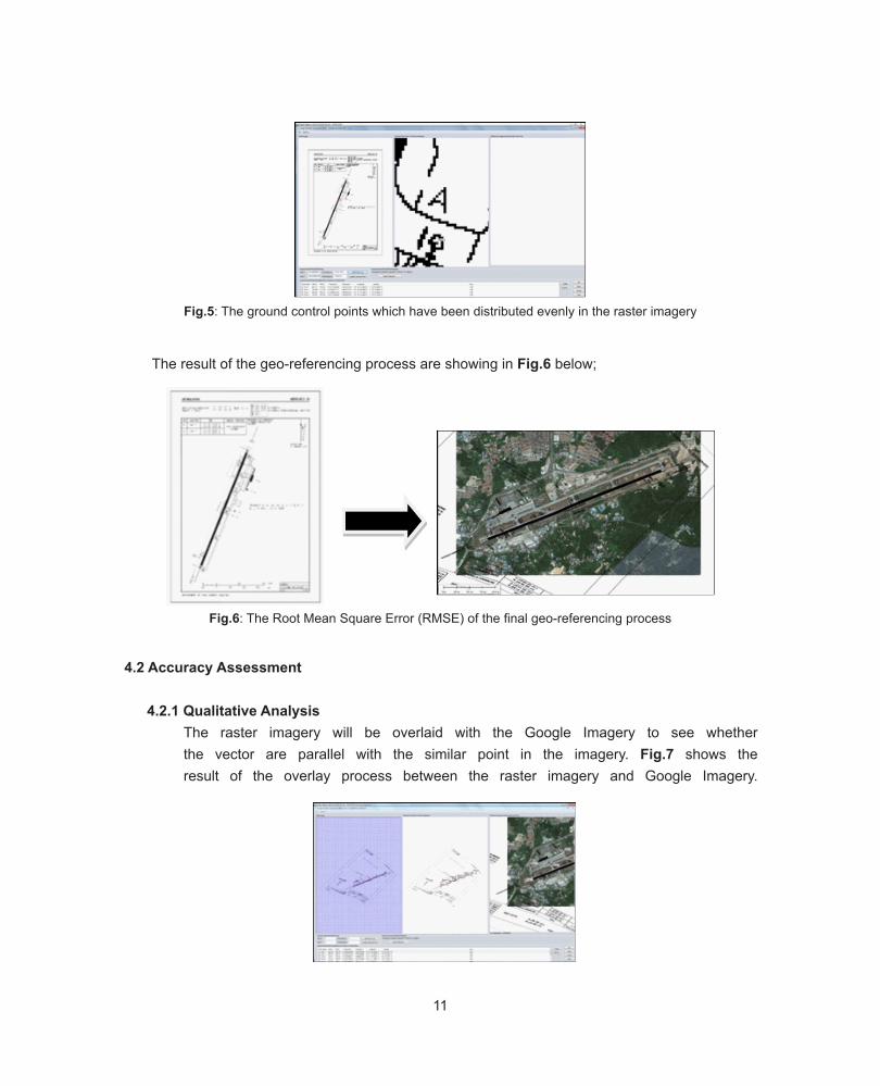
iii. Next, the ground control points will be keyed-in and will be distributed evenly within the raster imagery. At least four (4) points shall be selected in the raster imagery as showing in Fig.5. This task is quiet difficult, the geo-coding process is different compared to image geo-coding process because of there are a lot of features which can be utilized within the imagery. For geo- coding the rasterized aeronautical chart, the points will be distributed within the runway and the man-made features within the aerodrome.
However, before this process conducted, first, the selected coordinate’s points for geo-referencing process shall be selected. Google Imagery will be used as a based map to assess the latitude and longitudinal position of the selected points. Fig.4b shows how the procedure which was carried-out in Google Earth application.
11
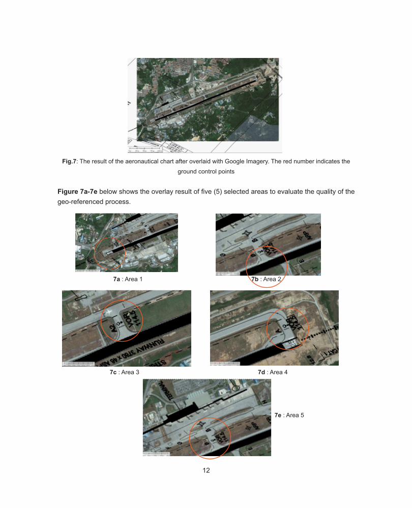
The result of the geo-referencing process are showing in Fig.6 below;
4.2 Accuracy Assessment
4.2.1 Qualitative Analysis The raster imagery will be overlaid with the Google Imagery to see whether
the vector are parallel with the similar point in the imagery. Fig.7 shows the result of the overlay process between the raster imagery and Google Imagery.
Fig.5: The ground control points which have been distributed evenly in the raster imagery
Fig.6: The Root Mean Square Error (RMSE) of the final geo-referencing process
12
Fig.7: The result of the aeronautical chart after overlaid with Google Imagery. The red number indicates the
ground control points
Figure 7a-7e below shows the overlay result of five (5) selected areas to evaluate the quality of the geo-referenced process.
7a : Area 1 7b : Area 2
7c : Area 3 7d : Area 4
7e : Area 5

13
4.3 Quantitative Accuracy Assessment Procedure
In this procedure, a comparison analysis between the surveyed data and the imagery has beencarried-out to assess the accuracy of the data. Nevertheless, it should be noted that Google Imagery is only suitable for viewing and will give a roughly accuracy of the points selected. Thus for precise and accurate measurement, the high resolution imagery of an airport area shall be acquired as it is more reliable and accurate.
The points measured are based on provision in Annex 14, Appendix 5: Aeronautical Data Quality Requirement and Appendix 6: Aeronautical Data Quality Requirements (Table 1-6).
The ground survey report conducted by Licensed Land Surveyor will be used as a reference points to assess the accuracy of the aeronautical chart.
Malaysia Airport Holding Berhad (MAHB) has appointed a licensed land surveyor firm to undergo a ground survey mapping for Kuching International Airport. Particular data of the aerodrome has been surveyed to fulfill the requirement of Aeronautical Information Services (AIS) such as;
i. Location of the Aerodrome; ii. Geographical coordinates of aerodrome reference point (ARP) based on World Geodetic System (WGS)- 84 reference datum; iii. Aerodrome elevation and geoids undulation iv. Elevation of each threshold and geoid undulation, elevation of each runway end and significant high and low points along the runway and the highest elevation of the touchdown zone of precision approach runway; v. Aerodrome dimensions and related information- - Runway - Taxiway - Location of DVOR/DME and VOR aerodrome checkpoints - Geographical coordinates of each threshold - Geographical coordinates of taxiway centerline points - Geographical coordinates of each aircraft stands - Declared distances
14
15
To a
chie
ve th
e be
st a
ccur
acy
poss
ible
of t
he s
urve
ying
, a G
PS e
quip
men
t (To
pcon
Sys
tem
) an
d a
Tota
l Sta
tion
(Nik
on D
TM)
was
utiliz
ed fo
r thi
s w
ork.
GN
SS s
urve
ying
tech
niqu
es u
sing
Mal
aysi
a- R
eal T
ime
Kine
mat
ic (M
y-R
TK) m
etho
ds h
as b
een
adop
ted
whe
re
the
mai
n co
ntro
l sta
tions
hav
e be
en e
stab
lishe
d w
ithin
the
Aero
drom
e ar
ea.
The
proc
edur
e ar
e as
follo
ws;
Pre-
Surv
ey W
orks
MAH
B D
eter
min
atio
n of
la
nd su
rvey
ing
w
ork
.spec
ifica
tions
A
ppoi
nted
the
Licen
sed
Land
Su
rvey
or F
irm.
Surv
eyin
g W
orks
MAH
B& A
irpor
t St
anda
rd D
ivisi
on
(DCA
) S
uper
vise
d an
d m
onito
ring
of
surv
eyin
g w
orks
by
MAH
B an
d Ai
rpor
t Sta
ndar
d Di
visio
n.
Sur
vey
Repo
rts
Post
Sur
veyi
ng W
orks
MAH
B& A
irpor
t St
anda
rd D
ivisi
on
(DCA
) T
he fi
nal s
urve
y re
port
subm
itted
to
MAH
B.
Lice
nsed
Land
Su
rvey
or w
ill
pres
ente
d th
e su
rvey
re
sult
in th
e m
eetin
g w
ith M
AHB
and
DCA.
A
ll th
e su
rvey
dat
a w
ill b
e an
alyz
ed
base
d on
the
prov
ision
of A
nnex
14
and
Doc9
674.
Data
Acc
urac
y As
sess
men
t
Air T
raffi
c Man
agem
ent
(DCA
) D
evel
oped
the
met
hodo
logy
to a
sses
s the
ac
cura
cy o
f the
surv
eyin
g da
ta (Q
ualit
ativ
e an
d Q
uant
itativ
e An
alys
is)
Yes?
END
No?
Rep
ort
diffi
cienc
y to
Ai
rpor
t St
anda
rd
Divi
sion
(DCA
)
Fig.
8: T
he P
re-D
eter
min
atio
n an
d th
e W
ork
Flow
of t
he S
urve
ying
Pro
cess
15
For quantitative assessment procedure, a selected samples from ground surveying data will be fully utilized to assess the accuracy of the surveyed data. The data from AIP also will be referred upon to check the value of the points such as ARP, DVOR and etc. ASTER GDEM with 1.5 arc second resolution (38-m vertical resolution) will be utilized to assess the terrain data.
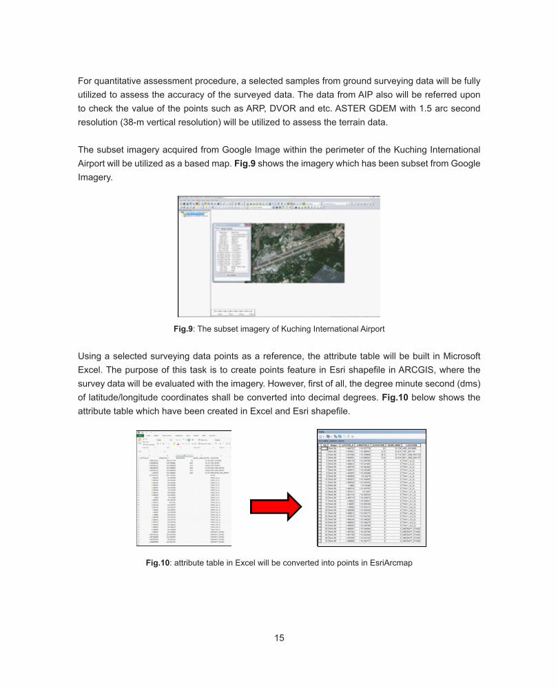
The subset imagery acquired from Google Image within the perimeter of the Kuching International Airport will be utilized as a based map. Fig.9 shows the imagery which has been subset from Google Imagery.
Fig.9: The subset imagery of Kuching International Airport
Using a selected surveying data points as a reference, the attribute table will be built in Microsoft Excel. The purpose of this task is to create points feature in Esri shapefile in ARCGIS, where the survey data will be evaluated with the imagery. However, first of all, the degree minute second (dms) of latitude/longitude coordinates shall be converted into decimal degrees. Fig.10 below shows the attribute table which have been created in Excel and Esri shapefile.
Fig.10: attribute table in Excel will be converted into points in EsriArcmap
16
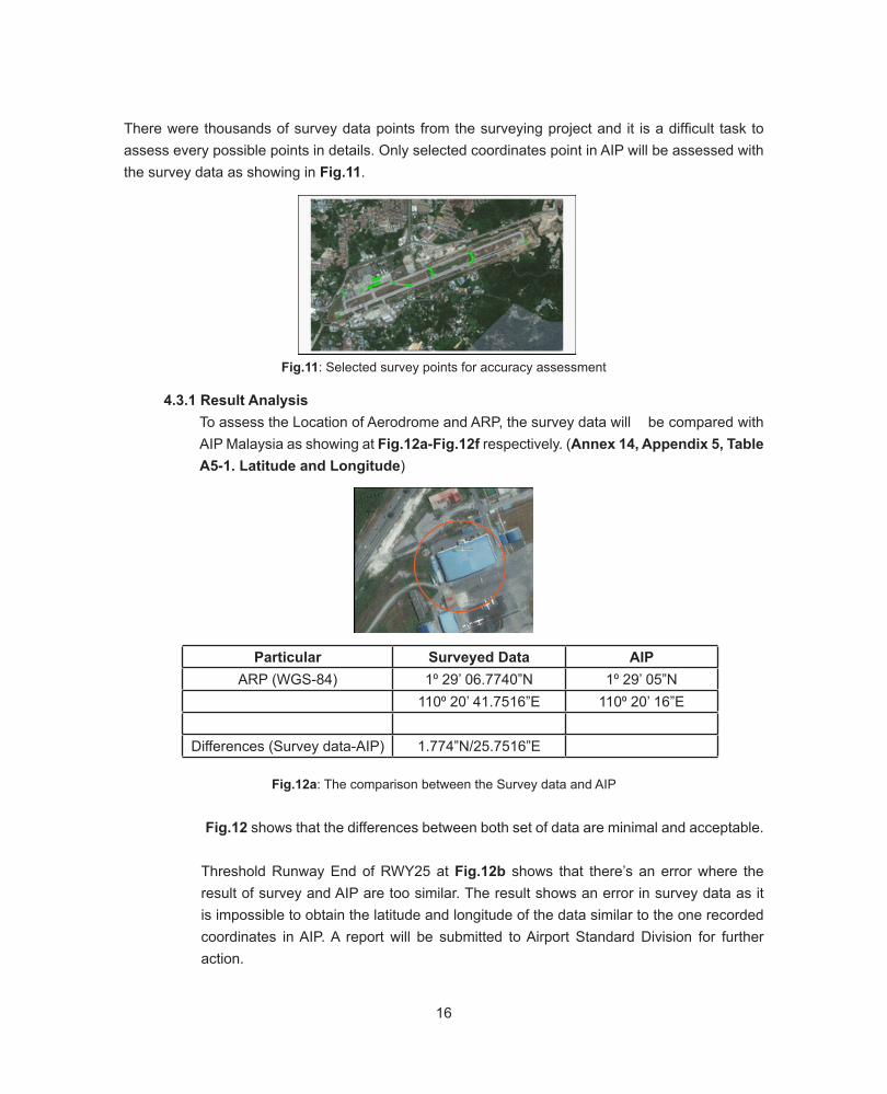
There were thousands of survey data points from the surveying project and it is a difficult task to assess every possible points in details. Only selected coordinates point in AIP will be assessed with the survey data as showing in Fig.11.
Fig.12a: The comparison between the Survey data and AIP Fig.12 shows that the differences between both set of data are minimal and acceptable.
Threshold Runway End of RWY25 at Fig.12b shows that there’s an error where the result of survey and AIP are too similar. The result shows an error in survey data as it is impossible to obtain the latitude and longitude of the data similar to the one recorded coordinates in AIP. A report will be submitted to Airport Standard Division for further action.
Fig.11: Selected survey points for accuracy assessment
4.3.1 Result Analysis To assess the Location of Aerodrome and ARP, the survey data will be compared with
AIP Malaysia as showing at Fig.12a-Fig.12f respectively. (Annex 14, Appendix 5, Table A5-1. Latitude and Longitude)
Particular Surveyed Data AIPARP (WGS-84) 1⁰ 29’ 06.7740”N 1⁰ 29’ 05”N
110⁰ 20’ 41.7516”E 110⁰ 20’ 16”E
Differences (Survey data-AIP) 1.774”N/25.7516”E
17
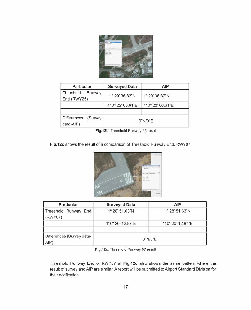
Fig.12c shows the result of a comparison of Threshold Runway End, RWY07.
Particular Surveyed Data AIPThreshold Runway End (RWY25)
1⁰ 29’ 36.82”N 1⁰ 29’ 36.82”N
110⁰ 22’ 06.61”E 110⁰ 22’ 06.61”E
Differences (Survey data-AIP)
0”N/0”E
Particular Surveyed Data AIPThreshold Runway End (RWY07)
1⁰ 28’ 51.63”N 1⁰ 28’ 51.63”N
110⁰ 20’ 12.87”E 110⁰ 20’ 12.87”E
Differences (Survey data-AIP)
0”N/0”E
Threshold Runway End of RWY07 at Fig.12c also shows the same pattern where the result of survey and AIP are similar. A report will be submitted to Airport Standard Division for their notification.
Fig.12c: Threshold Runway 07 result
Fig.12b: Threshold Runway 25 result
18
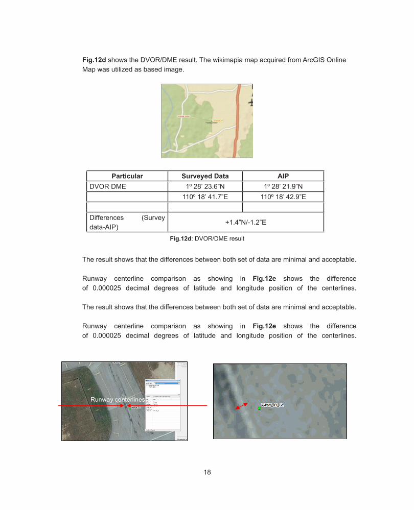
Fig.12d shows the DVOR/DME result. The wikimapia map acquired from ArcGIS Online Map was utilized as based image.
The result shows that the differences between both set of data are minimal and acceptable.
Runway centerline comparison as showing in Fig.12e shows the difference of 0.000025 decimal degrees of latitude and longitude position of the centerlines.
The result shows that the differences between both set of data are minimal and acceptable.
Runway centerline comparison as showing in Fig.12e shows the difference of 0.000025 decimal degrees of latitude and longitude position of the centerlines.
Particular Surveyed Data AIPDVOR DME 1⁰ 28’ 23.6”N 1⁰ 28’ 21.9”N
110⁰ 18’ 41.7”E 110⁰ 18’ 42.9”E
Differences (Survey data-AIP)
+1.4”N/-1.2”E
20
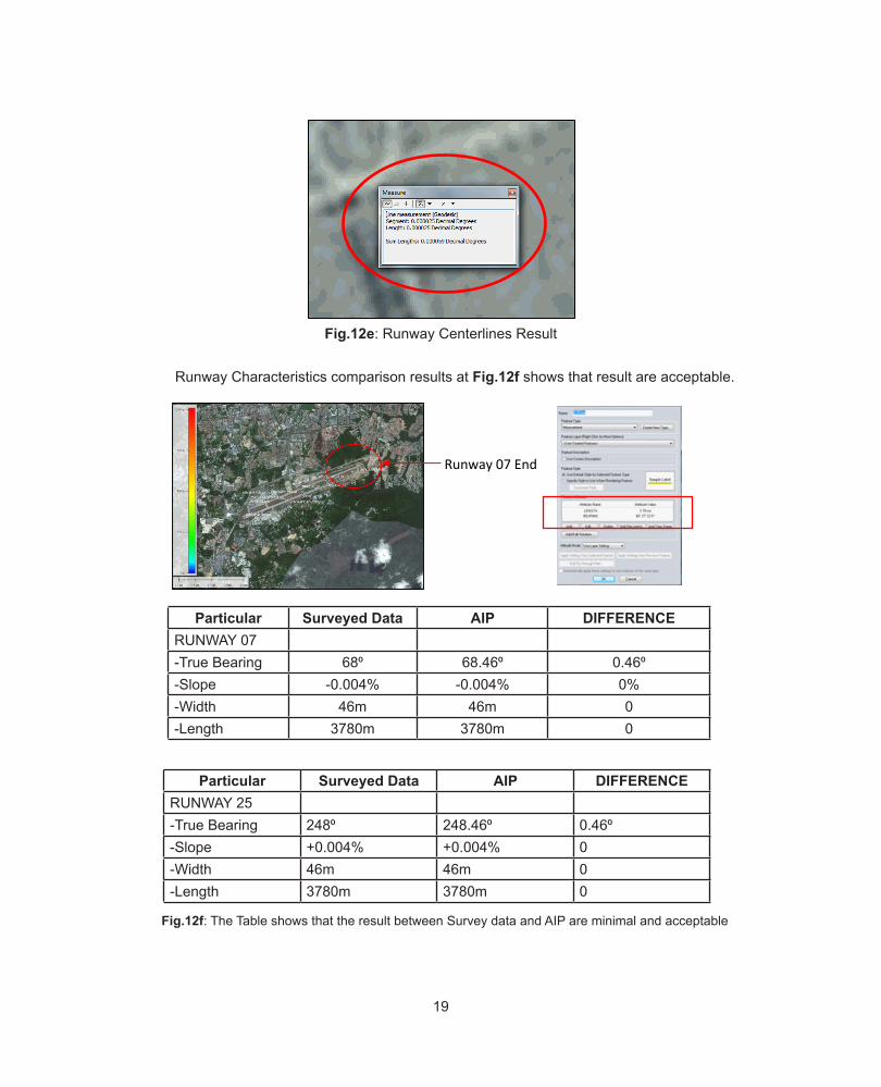
Fig.12e: Runway Centerlines Result
Runway Characteristics comparison results at Fig.12f shows that result are acceptable.
Runway centerlines
Runway 07 End
20
Fig.12e: Runway Centerlines Result
Runway Characteristics comparison results at Fig.12f shows that result are acceptable.
Runway centerlines
Runway 07 End
Fig.12d: DVOR/DME result
19
Runway Characteristics comparison results at Fig.12f shows that result are acceptable.
Particular Surveyed Data AIP DIFFERENCERUNWAY 07-True Bearing 68⁰ 68.46⁰ 0.46⁰-Slope -0.004% -0.004% 0%-Width 46m 46m 0-Length 3780m 3780m 0
Particular Surveyed Data AIP DIFFERENCERUNWAY 25-True Bearing 248⁰ 248.46⁰ 0.46⁰-Slope +0.004% +0.004% 0-Width 46m 46m 0-Length 3780m 3780m 0
20
Fig.12e: Runway Centerlines Result
Runway Characteristics comparison results at Fig.12f shows that result are acceptable.
Runway centerlines
Runway 07 End
20
Fig.12e: Runway Centerlines Result
Runway Characteristics comparison results at Fig.12f shows that result are acceptable.
Runway centerlines
Runway 07 End
Fig.12e: Runway Centerlines Result
Fig.12f: The Table shows that the result between Survey data and AIP are minimal and acceptable
20
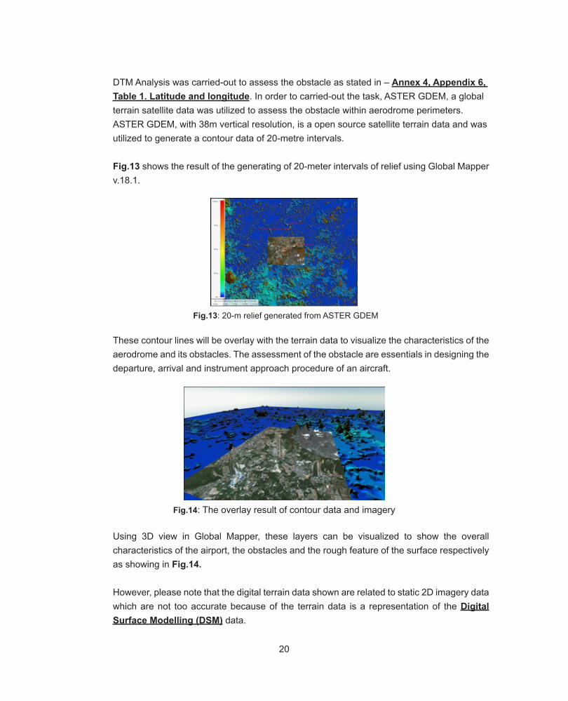
DTM Analysis was carried-out to assess the obstacle as stated in – Annex 4, Appendix 6, Table 1. Latitude and longitude. In order to carried-out the task, ASTER GDEM, a global terrain satellite data was utilized to assess the obstacle within aerodrome perimeters. ASTER GDEM, with 38m vertical resolution, is a open source satellite terrain data and was utilized to generate a contour data of 20-metre intervals. Fig.13 shows the result of the generating of 20-meter intervals of relief using Global Mapper v.18.1.
These contour lines will be overlay with the terrain data to visualize the characteristics of the aerodrome and its obstacles. The assessment of the obstacle are essentials in designing the departure, arrival and instrument approach procedure of an aircraft.
Using 3D view in Global Mapper, these layers can be visualized to show the overall characteristics of the airport, the obstacles and the rough feature of the surface respectively as showing in Fig.14.
However, please note that the digital terrain data shown are related to static 2D imagery data which are not too accurate because of the terrain data is a representation of the Digital Surface Modelling (DSM) data.
Fig.13: 20-m relief generated from ASTER GDEM
Fig.14: The overlay result of contour data and imagery
21
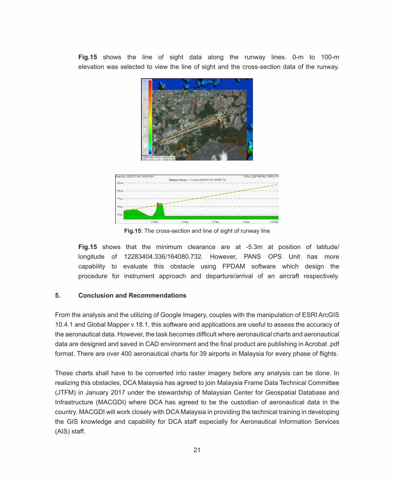
Fig.15 shows the line of sight data along the runway lines. 0-m to 100-m elevation was selected to view the line of sight and the cross-section data of the runway.
Fig.15 shows that the minimum clearance are at -5.3m at position of latitude/ longitude of 12283404.336/164080.732. However, PANS OPS Unit has more capability to evaluate this obstacle using FPDAM software which design the procedure for instrument approach and departure/arrival of an aircraft respectively.
5. Conclusion and Recommendations
From the analysis and the utilizing of Google Imagery, couples with the manipulation of ESRI ArcGIS 10.4.1 and Global Mapper v.18.1, this software and applications are useful to assess the accuracy of the aeronautical data. However, the task becomes difficult where aeronautical charts and aeronautical data are designed and saved in CAD environment and the final product are publishing in Acrobat .pdf format. There are over 400 aeronautical charts for 39 airports in Malaysia for every phase of flights.
These charts shall have to be converted into raster imagery before any analysis can be done. In realizing this obstacles, DCA Malaysia has agreed to join Malaysia Frame Data Technical Committee (JTFM) in January 2017 under the stewardship of Malaysian Center for Geospatial Database and Infrastructure (MACGDI) where DCA has agreed to be the custodian of aeronautical data in the country. MACGDI will work closely with DCA Malaysia in providing the technical training in developing the GIS knowledge and capability for DCA staff especially for Aeronautical Information Services (AIS) staff.
Fig.15: The cross-section and line of sight of runway line
22
The restructuring of aeronautical data to follow the standard requirement of MS1759 (Malaysian Standard for Feature Codes and Attributes) is the first initiative to be taken in realizing this project. This is also in line with the initiatives introduced by ICAO’s Strategic Objectives where ICAO are working closely and collaborating with the entire air transport community, to further improve aviation’s successful safety performance while maintaining a high level of capacity and efficiency. Through ICAO’s Strategic Objectives, Global Aviation Safety Plan (GASP) and the Global Air Navigation Plan (GANP) will be implemented to achieve the objective.
One of the main improvement areas in Aeronautical Service Block Upgrade (ASBU) is the recognition of globally interoperable systems & data. There are three modules under B0-30 Service Improvement where the utilizing Digital Aeronautical Information Management Initial of digital processing and management of information to move into electronic AIP and better quality and availability of data. One of the data utilized under this block is electronic Terrain and Obstacle Data (eTOD). Digital terrain data to be utilized is high resolution Synthetic Aperture Radar (SAR) data such as IFSAR and LIDAR data. These digital terrain data will be utilized in designing and assessing the obstacles topographic data within the radius of aerodrome area to provide accurate analysis for efficiency and safe flight.
The objective of the procedure developed is to evaluate and assess the accuracy of the aeronautical data in order to meet the requirement of ICAO’s Universal Safety Oversight Audit Program (USOAP) Continuous Monitoring Approach (CMA) audit. One of the technique is converting and transforming the CAD environment format to GIS friendly format such as Esri shapefile. With the emergence of latest mapping applications such as Online Imagery, the data can be assessed. However, it is highly recommended to improved the procedure by assessing the data in the field by collecting the information on the ground using Global Positioning System (GPS) equipment.
The next level and the most important part is sustaining the development of GIS in DCA Malaysia and furthermore improving the utilizing and the capabilities of the current staff to fulfill the required standards in implementing this procedures. Nonetheless, the procedure is an early initiative developed to meet the requirement of aeronautical data accuracy set by ICAO and this procedure will be slowly improved when the aeronautical charts and the aeronautical data have been converted and transformed to more GIS friendly format where the data can be analyzed and evaluated with other geospatial data respectively.
Note:This procedure was developed and implemented by the writer while he was working as Geospatialist/Geospatial Engineer/Aviation Cartographer at Department of Civil Aviation Malaysia. The procedure was developed for ICAO’s USOAP CMA auditing specifically for providing the methods and techniques to evaluate and assessing the accuracy of the aeronautical data for Protocol Question (P.Q.) 7.359.
23
Reference
1. https://www.icao.int/safety/CMAForum/Pages/default.aspx2. https://www.icao.int/safety/CMAForum/Pages/default.aspx3. http://aviationweek.com/business-aviation/saying-yes-portable-electronic-devices4. desktop.arcgis.com/en/arcmap/10.3/manage-data/raster.../what-is-raster-data.htm5. https://www.icao.int/safety/Pages/GASP.aspx6. https://www.icao.int/SAM/Documents/OPMET12/ASBU%20Bloque%200.pdf#search=Search%2E%2E%2Easbu7. https://www.icao.int/airnavigation/Documents/ASBU_2016-FINAL.pdf8. ICAO Annex 4, Appendix 6, Table 1. Latitude and longitude 9. ICAO Annex 14, Appendix 5: Aeronautical Data Quality Requirement and Appendix 6: Aeronautical Data Quality Requirements (Table 1-6)
Abbreviation
ADEX: Air Defense ExerciseAIS: Aeronautical Information ServicesAIP: Aeronautical Information PublicationARP: Aerodrome PointASBU: Aeronautical Service Block UpgradeASTER GDEM: The ASTER Global Digital Elevation Model (ASTER GDEM) is a joint product developed and made available to the public by the Ministry of Economy, Trade, and Industry (METI) of Japan and the United States National Aeronautics and Space Administration (NASA) (www.jspacesystems.or.jp/ersdac/GDEM/E/4.html)ATM: Air Traffic ManagementDME: Distance Measurement EquipmentDSM: Digital Surface ModelingDTM: Digital Terrain ModelingDVOR: Doppler VHF Omni Directional RangeeTOD: Electronic Terrain and Obstacle DataFPDAM: Flight Procedure Design & Airspace ManagementGANP: Global Air Navigation PlanGASP: Global Aviation Safety PlanICAO’s USOAP CMA: Universal Safety Oversight Audit Program (USOAP) Continuous Monitoring Approach (CMA)IFSAR: Interferometric Synthetic Aperture Radar. Developed just in recent years, IFSAR is a powerful approach in generating high-resolution digital data through the use of Digital Elevation Model (DEM) and an orthorectified radar image (www.certezainfosys.com/ifsar.php)LIDAR: Light Detection and Ranging, a detection system that works on the principle of radar, but uses light from a laser.MAHB: Malaysian Airport Holding BerhadMy-AIMS: Malaysia Aeronautical Information Management SystemPANS-OPS: Procedure of Air Flight Navigation System and OperationsSAREX: Search & Rescue ExerciseSTOLPORT: An airport designed with STOL (Short Take-Off and Landing) operations in mind, usually for an aircraft class of its weight and size.VOR: VHF Omni Directional RangeWGS-84: World Geodetic System
24
ZON-ZON SEMPADAN MARITIM BERPANDUKAN KEPADA KONVENSYEN UNDANG-UNDANG LAUT 1982 (KUUL 1982)
Sr Zakaria bin Abdullah
Tim Khas Projek Pelantar Benua MalaysiaBahagian Keselamatan dan Kedaulatan Maritim
Majlis Keselamatan Negara (MKN)
Bahagian Ehwal PersempadananTingkat 8, Wisma JUPEMJalan Sultan Yahya Petra
50578 Kuala LumpurEmail: [email protected]
ABSTRAK
Menurut Konvensyen Undang-Undang Laut 1982 (KUUL 1982) zon sempadan maritim boleh dibahagikan kepada 7 zon maritim iaitu Perairan Dalaman, Zon Laut Wilayah, Zon Berdampingan, Zon Ekonomi Eksklusif, Pelantar Benua, Laut Lepas dan Dasar Laut Antarabangsa. Setiap zon yang dinyatakan di atas mempunyai undang-undangnya tersendiri. Sesebuah Negara iaitu Negara yang mempunyai pantai atau Negara yang dikeliling laut layak untuk membuat tuntutan ke atas zon-zon tersebut. Setiap tuntutan yang dibuat oleh Negara tersebut hendaklah berpandukan kepada KUUL 1982. Dalam artikel ini, ianya akan menerangkan tentang jarak dan kepentingan zon-zon sempadan maritim.
1.0 Pendahuluan
Menurut Dundua (2007), undang-undang laut antarabangsa merupakan undang-undang yang sukar, luas dan terdiri daripada norma-norma hak dan tanggungjawab bagi sesebuah negara pantai. Setiap negara pantai mempunyai hak dan bidang kuasa ke atas laut dan laut lepas. Hak dan bidang kuasa sesebuah negara pantai adalah tertakluk kepada zon-zon yang telah ditakrifkan oleh KUUL 1982. Sebelum hak dan bidang kuasa itu dikuatkuasakan, negara pantai hendaklah menandatangani dan mengesahkan KUUL 1982 terlebih dahulu. Menurut Dundua lagi, kerjasama dalam isu-isu yang melibatkan persempadanan maritim oleh setiap negara pantai adalah sangat penting dalam usaha mengekalkan keamanan, keselamatan dan ekonomi serantau.
Penentuan had sempadan maritim antara dua atau lebih negara pantai adalah dikawal oleh prinsip-prinsip dan kaedah-kaedah KUUL (Schofield, 1999). Konvensyen PBB telah merekodkan banyak peraturan dan prinsip yang berkaitan dengan undang-undang laut dan persempadanan
25
maritim yang dijadikan asas oleh ICJ dan rundingan antara negara-negara pantai dalam membuat keputusan.
Sesebuah negara pantai mempunyai hak untuk menentukan had sempadan maritim selagi ianya tidak melanggar KUUL 1982. Ianya merupakan konvensyen yang menerangkan hak-hak dan kaedah-kaedah bagi sebuah negara pantai menentukan sempadan maritim.
1.1 Konvensyen Undang-Undang Laut 1982 (KUUL 1982)
Konvensyen Undang-Undang Laut 1982 (KUUL 1982) telah ditandatangani di Montego Bay, Jamaica, pada 10 Disember 1982. Pada 18 Januari 1984, sebanyak 133 negara telah menandatangani KUUL 1982 dan sembilan buah negara telah mengesahkannya (Chiu, 1985). KUUL 1982 telah berkuatkuasa pada 16 November 1994 dan ianya telah ditandatangani sebanyak 159 buah negara, di mana ianya terdiri daripada, 320 Artikel, 17 Bahagian dan 9 Lampiran serta Akta Akhir.
Ciri-ciri utama yang terdapat di dalam KUUL 1982 adalah menerangkan berkenaan dengan definisi had maritim dan had pelbagai zon maritim, peraturan untuk perlindungan dan pemuliharaan persekitaran lautan dari pencemaran, penyelidikan saintifik marin, kaedah untuk penyelesaian pertikaian sempadan bagi mengelakkan pertelingkahan antara negara pantai.
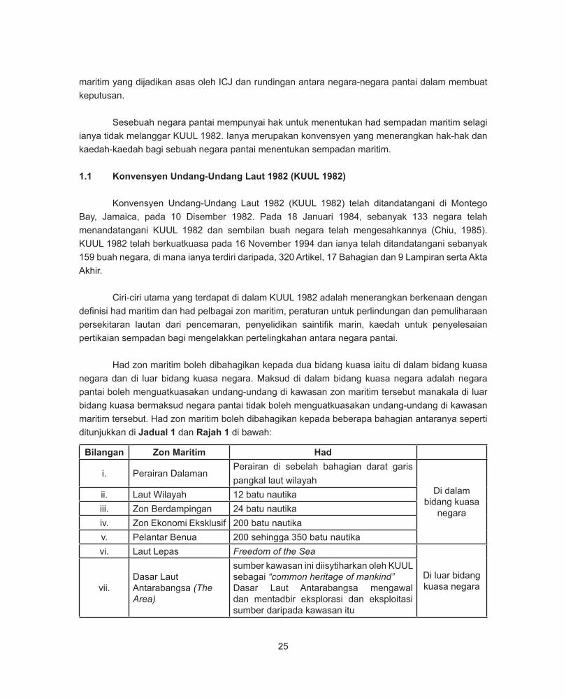
Had zon maritim boleh dibahagikan kepada dua bidang kuasa iaitu di dalam bidang kuasa negara dan di luar bidang kuasa negara. Maksud di dalam bidang kuasa negara adalah negara pantai boleh menguatkuasakan undang-undang di kawasan zon maritim tersebut manakala di luar bidang kuasa bermaksud negara pantai tidak boleh menguatkuasakan undang-undang di kawasan maritim tersebut. Had zon maritim boleh dibahagikan kepada beberapa bahagian antaranya seperti ditunjukkan di Jadual 1 dan Rajah 1 di bawah:
Bilangan Zon Maritim Had
i. Perairan DalamanPerairan di sebelah bahagian darat garis pangkal laut wilayah
Di dalam bidang kuasa
negara
ii. Laut Wilayah 12 batu nautikaiii. Zon Berdampingan 24 batu nautikaiv. Zon Ekonomi Eksklusif 200 batu nautikav. Pelantar Benua 200 sehingga 350 batu nautikavi. Laut Lepas Freedom of the Sea
Di luar bidang kuasa negaravii.
Dasar Laut Antarabangsa (The Area)
sumber kawasan ini diisytiharkan oleh KUUL sebagai “common heritage of mankind”Dasar Laut Antarabangsa mengawal dan mentadbir eksplorasi dan eksploitasi sumber daripada kawasan itu
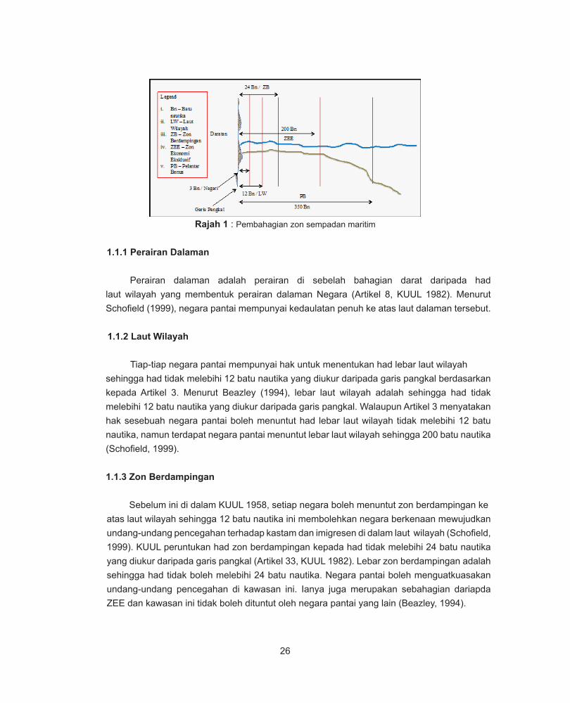
26
Rajah 1 : Pembahagian zon sempadan maritim
1.1.1 Perairan Dalaman
Perairan dalaman adalah perairan di sebelah bahagian darat daripada had laut wilayah yang membentuk perairan dalaman Negara (Artikel 8, KUUL 1982). Menurut Schofield (1999), negara pantai mempunyai kedaulatan penuh ke atas laut dalaman tersebut.
1.1.2 Laut Wilayah
Tiap-tiap negara pantai mempunyai hak untuk menentukan had lebar laut wilayah sehingga had tidak melebihi 12 batu nautika yang diukur daripada garis pangkal berdasarkan
kepada Artikel 3. Menurut Beazley (1994), lebar laut wilayah adalah sehingga had tidak melebihi 12 batu nautika yang diukur daripada garis pangkal. Walaupun Artikel 3 menyatakan hak sesebuah negara pantai boleh menuntut had lebar laut wilayah tidak melebihi 12 batu nautika, namun terdapat negara pantai menuntut lebar laut wilayah sehingga 200 batu nautika (Schofield, 1999).
1.1.3 Zon Berdampingan
Sebelum ini di dalam KUUL 1958, setiap negara boleh menuntut zon berdampingan ke atas laut wilayah sehingga 12 batu nautika ini membolehkan negara berkenaan mewujudkan undang-undang pencegahan terhadap kastam dan imigresen di dalam laut wilayah (Schofield, 1999). KUUL peruntukan had zon berdampingan kepada had tidak melebihi 24 batu nautika yang diukur daripada garis pangkal (Artikel 33, KUUL 1982). Lebar zon berdampingan adalah sehingga had tidak boleh melebihi 24 batu nautika. Negara pantai boleh menguatkuasakan undang-undang pencegahan di kawasan ini. Ianya juga merupakan sebahagian dariapda ZEE dan kawasan ini tidak boleh dituntut oleh negara pantai yang lain (Beazley, 1994).
27
1.1.4 Zon Ekonomi Eksklusif (ZEE)
Kawasan yang melewati and bersebelahan dengan Laut Wilayah, tertakluk kepada peraturan yang sah (Artikel 55, KUUL 1982), di mana hak dan kuasa negara persisir serta hak dan kebebasan negara lain dikawal oleh peruntukan dalam KUUL. Had lebar ZEE tidak boleh melebihi 200 batu nautika dikira dari Garis Pangkal dari mana kelebaran Laut Wilayah diukur (Artikel 57, KUUL 1982). Di dalam KUUL 1982 telah menyatakan kuasa sesebuah negara pantai bagi ZEE adalah seperti berikut:
a. Aktiviti ekonomi dalam kawasan perairan dan dasar lautb. Menjalankan penyelidikan saintifik marinc. Memelihara alam sekitard. Membina dan menggunakan pulau buatan, pangkalan dan struktur di dalam kawasan EEZ
Dalam menjalankan penguatkuasaan mengikut peruntukan yang ditetapkan oleh KUUL 1982, negara pantai juga harus memberi perhatian kepada hak dan tanggungjawab negara-negara lain. Menurut Beazley (1994), ZEE adalah bersebelahan dengan laut wilayah dan lebar kawasan ZEE adalah sehingga 200 batu nautika diukur daripada garis pangkal. Negara pantai mempunyai hak untuk mengeksploitasi, memulihara dan menguruskan sumber asli, hidupan serta bukan hidupan di dasar laut dan di tanah bawah dasar laut. Di dalam KUUL 1982, sesebuah negara pantai mempunyai hak dan tanggungjawab di dalam zon ZEE antaranya:
a. Hak untuk mengeksploitasi, memulihara dan mengurus sumber asli, hidup atau bukan hidup. Di dasar laut dan tanah bawah dasar laut (Artikel 56, KUUL 1982).
b. Memulihara sumber laut dalam kawasan ZEE dengan mengambil kira data saintifik dan pengurusan yang baik (Artikel 61, KUUL 1982).c. Penggunaan dan mengambilan sumber laut secara optimum dan berhemah supaya sumber tersebut dapat dipulihara dengan baik, termasuk dalam pemberian lesen menangkap ikan dan sebagainya (Artikel 62, KUUL 1982).d. Mengadakan peruntukan dan peraturan yang terperinci dalam pengurusan sumber di kawasan ZEE dan memberi notis mengenai peraturan serta peruntukan yang dibuat (Artikel 62, KUUL 1982).
1.1.5 Pelantar Benua
Sesebuah negara pantai berhak untuk menuntut sempadan pelantar benua sehingga had tidak melebihi 350 batu nautika berpandukan kepada Artikel 76. Kajian saintifik hendaklah dijalankan untuk dijadikan sebagai bukti bahawa sesebuah negara pantai itu berhak untuk menuntut sempadan pelantar benua (Artikel 76, KUUL 1982).
28
Menurut Beazley (1994), pelantar benua adalah dasar laut dan tanah bawah dasar laut kawasan bawah laut yang menganjur melewati laut wilayah hingga ke birai bahagian tepi pelantar benua atau sehingga jarak 200 batu nautika dari garis pangkal dari mana kelebaran laut wilayah diukur sekiranya birai bahagian tepi pelantar benua tidak menjangkau lebih dari 200 batu nautika. Negara pantai berhak untuk membuat cari gali dan eksploitasi sumber asli dasar laut dan tanah di bawah dasar laut.
1.1.6 Laut Lepas
Laut Lepas adalah semua bahagian laut yang tidak termasuk di dalam ZEE, laut wilayah atau perairan dalaman (Artikel 86, KUUL 1982). Had laut lepas adalah kebebasan laut lepas iaitu :
a. Kebebasan untuk pelayaranb. Kebebasan penggunaan ruang udarac. Kebebasan untuk meletakkan kebal dasar laut dan paip dasar lautd. Mendirikan pulau buatan dan pemasangan lain yang dibenarkan di bawah undang- undang antarabangsae. Menaikkan hasil tangkapan sertaf. Membuat kajian Saintifik tertakluk kepada peruntukan lain dalam konvensyen ini
Bil Zon Maritim (batu nautika)
Bidang KuasaSumber Galian Penguatkuasaan
a) 3 Kerajaan Negeri (Akta Laut Wilayah 2012)
Kerajaan Persekutuan (Akta Perikanan 1985, Akta APPM
2006)b) 12 Kerajaan Persekutuan Kerajaan Persekutuan (Akta
Perikanan 1985, Akta APMM 2006)
c) 24 Tidak dipraktikan di Malaysia Tidak dipraktikan di Malaysiad) 200 Kerajaan Persekutuan Kerajaan Persekutuan (Akta ZEE
1984, Akta Perikanan 1985, Akta APMM 2006)
e) 350 Kerajaan Persekutuan Kerajaan Persekutuan (Akta Pelantar Benua 1966, Akta
APMM 2006)
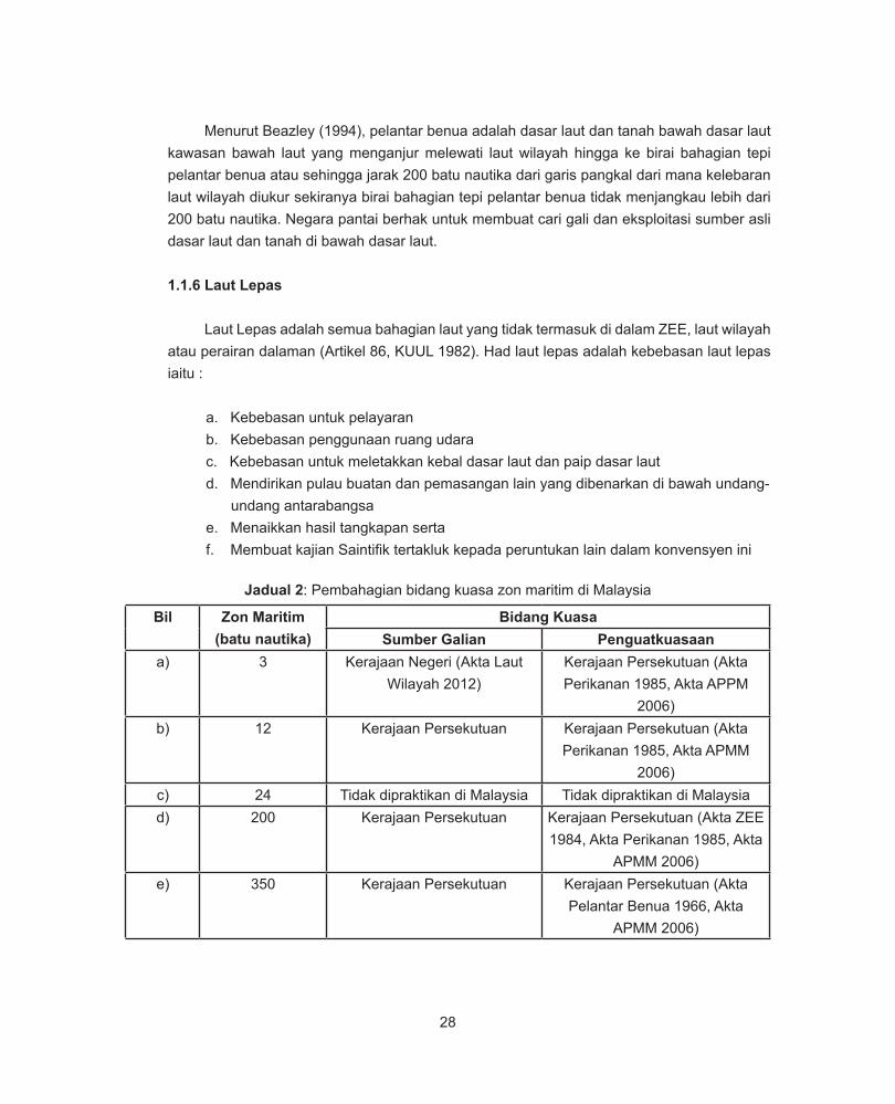
Jadual 2: Pembahagian bidang kuasa zon maritim di Malaysia
29
Jadual 2, menunjukkan pembahagian bidang kuasa zon maritim di Malaysia. Di Malaysia penguatkuasaan zon berdampingan iaitu sejauh 24 batu nautika tidak dipraktikan kerana ianya bertindih dengan Akta-Akta yang sedia ada.
RUJUKAN
Beazley, P.B. (1994). Technical Aspect of Maritime Boundary Delimitation. Maritime Briefing Volume 1 Number 2, University
of Durham, United Kingdom.
Chiu, H. (1985). Some Problems Concerning the Application of the Maritime Boundary Delimitation Provisions of the 1982
United Nations Convention on the Law of the Sea Between Adjacent or Opposite States. Maryland Journal of International
Law, 9(1), 1.
Dundua, N. (2007). Delimitation of maritime boundaries between adjacent States. United Nations, Division for Oceans Affairs
and the Law of the Sea, New York.
Schofield, C. H. (1999). Maritime boundary delimitation in the gulf of Thailand (Doctoral dissertation, Durham University),
United Kingdom.
United Nations (1982). The law of the Sea: United Nations Convention on the Law of the Sea 1982, United Nations, New York.
United Nations. Division for Ocean Affairs and the Law of the Sea (2000), Handbook on the delimitation of maritime boundaries,
New York ; Division of Ocean Affairs and the Law of the Sea, Office of Legal Affairs, United Nations, New York.
United Nations (1989). The Law of the Sea: Baseline: an Examination of the Relevant Provisions of the United Nations
Convention on the Law of the Sea. United Nations, New York
30
THE DEVELOPMENT OF MARINE GEODETIC INFRASTRUCTURESIN EAST MALAYSIA WATERS (2013 – 2017)
Dr. Sr Azhari bin Mohamed, Sr Sohaime bin Hj Rasidi, Sr Zulkafli bin Chihat, Sr Shabudin bin Saad
Jabatan Ukur dan Pemetaan MalaysiaJalan Sultan Yahya Petra, 50578 Kuala Lumpur
Dato’ Dr. Abd Majid A Kadir, Ahmad Fahmi bin Abd Majid, Syarifuddin bin Mat Zali
Info-Geomatik, 81300 Skudai, Johor
Assoc. Prof. Dr. Kamaludin Talib, Dr. Saiful Aman bin Sulaiman
Faculty of Architecture, Planning and Surveying,Universiti Teknologi MARA, 40450 Shah Alam, Selangor
SUMMARY
The aim of the MAGIC Project is to create and maintain modern marine geodetic infrastructures for Malaysia waters with the primary objective to preserve national sovereignty over marine area under its jurisdiction. In 2013 to 2017, MAGIC was implemented in the East Malaysia waters; bounded by the South China Sea to the northwest, the Sulu Sea to the northeast, and the Celebes Sea to the east, with a total marine area of approximately 407,000 square kilometers.
The scope of work of the East Malaysia MAGIC Project are: 1) To extend the Malaysian Geocentric Datum (GDM2000) through marine geodetic network (MGN) covering selected islands within East Malaysia waters; 2) To establish three Permanent Active Marine Geodetic GNSS Station (Marine CORS) with continuous GNSS tracking capability for strengthening GDM2000 in marine areas offshore of Sabah; 3) To establish Marine Geodetic Vertical Datum (MGVD) through airborne gravity and magnetic surveys within East Malaysia continental shelf areas; 4) To develop seamless land-to-sea topographic database through the integration with hydrographic surveys in some selected coastal areas of Sabah; and 5) To develop MAGIC Processing and Database Centre at JUPEM Headquarters. Marine Geodetic Database (MGDB) has been developed using ArcGIS Database System version 10.2 Geodatabase System. MGDB will serve as the foundation for the development of a comprehensive Marine Spatial Data Infrastructure (Marine SDI) for Malaysia.
31
1.0 PROJECT BACKGRAOUND
Malaysia is a maritime country with its land and marine areas of approximately 332,000 square km and 613,000 square km, respectively. The country claims an estimated of 4,700 km long coastal zone and a total of 1,370 islands including its offshore geographical entities. Due to the national sovereignty over the entities of the marine area, a Cabinet meeting on August 13th 2008 has came up with decission on a task to survey and positioning of all the islands to be given the highest priority. This task has been realized through the implementation of Marine Geodetic Infrastructures in Malaysian Waters (MAGIC) Project by Bahagian Ukur Geodetik, Jabatan Ukur Dan Pemetaan Malaysia. The aim of the MAGIC Project is to create and maintain modern marine geodetic infrastructures for Malaysia waters with the primary objective to preserve national sovereignty over marine area under its jurisdiction.
Table 1: Land and marine areas of Peninsular and East Malaysia
As a maritime country, Malaysia is very much dependent on the extent of its marine area for its diverse interests in national safety, international trade, maritime transportation, marine environment, marine natural resources, food resources, tourism and many more. With respect to these interests, the task to survey and positioning of islands in Malaysian water need to be supported with additional sea-land interface measurement initiatives leading to the creation of other fundamental marine geodetic information such as seabed topography, marine gravity and magnetic fields, and precise marine geoid. Such a comprehensive effort of marine measurements has been carried out with ultimate aim to establish a Marine Geodetic Database (MGDB) for Malaysia.
In 2013 to 2017, MAGIC was implemented in the East Malaysia waters; bounded by the South China Sea to the northwest, the Sulu Sea to the northeast, and the Celebes sea to the east, with a total marine area of approximately 407,800 square kilometers (see Figure 1).The scope of work of the East Malaysia MAGIC Project are: 1) To extend the Malaysian Geocentric Datum (GDM2000) through marine geodetic network (MGN) covering selected islands within East Malaysian waters; 2) To establish three Marine Permanent GNSS Permanent Stations (Marine CORS) with continuous GNSS tracking capability for strengthening GDM2000 in marine areas offshore of Sabah; 3) To establish Marine Geodetic Vertical Datum (MGVD) through airborne gravity and magnetic surveys within the East Malaysia continental shelf areas; 4) To develop seamless land-to-sea topographic database through the integration with hydrographic surveys in some selected coastal areas of Sabah; and 5) To develop MAGIC Processing and Database Centre at JUPEM Headquarters.
Land Area(square km)
Marine Area(square km)
Total Area(square km)
Peninsular Malaysia 131,600 205,600 337,200East Malaysia 200,500 407,800 608,300
Total Area 332,100 613,400 945,500
32
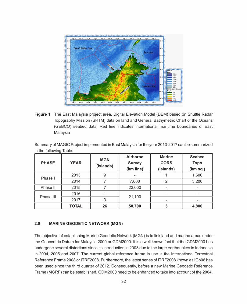
Figure 1: The East Malaysia project area. Digital Elevation Model (DEM) based on Shuttle Radar Topography Mission (SRTM) data on land and General Bathymetric Chart of the Oceans (GEBCO) seabed data. Red line indicates international maritime boundaries of East Malaysia
Summary of MAGIC Project implemented in East Malaysia for the year 2013-2017 can be summarized in the following Table:
2.0 MARINE GEODETIC NETWORK (MGN)
The objective of establishing Marine Geodetic Network (MGN) is to link land and marine areas under the Geocentric Datum for Malaysia 2000 or GDM2000. It is a well known fact that the GDM2000 has undergone several distortions since its introduction in 2003 due to the large earthquakes in Indonesia in 2004, 2005 and 2007. The current global reference frame in use is the International Terrestrial Reference Frame 2008 or ITRF2008. Furthermore, the latest series of ITRF2008 known as IGb08 has been used since the third quarter of 2012. Consequently, before a new Marine Geodetic Reference Frame (MGRF) can be established, GDM2000 need to be enhanced to take into account of the 2004,
PHASE YEARMGN
(islands)
AirborneSurvey
(km line)
MarineCORS
(islands)
SeabedTopo
(km sq.)
Phase I2013 9 - 1 1,6002014 7 7,600 2 3,200
Phase II 2015 7 22,000 - -
Phase III2016 -
21,100- -
2017 3 - -TOTAL 26 50,700 3 4,800
33
2005 and 2007 post-seismic distortions and linking to the current IGb08. Therefore, the initial step taken is to realized the 78 stations of the Malaysia Real Time Kinematics Network (MyRTKnet) in the IGb08 system by linking these stations to 50 International GNSS Service (IGS) stations. For the purpose of establishing the MGRF, GPS data consisting of seven (7) days continuous data has been used.
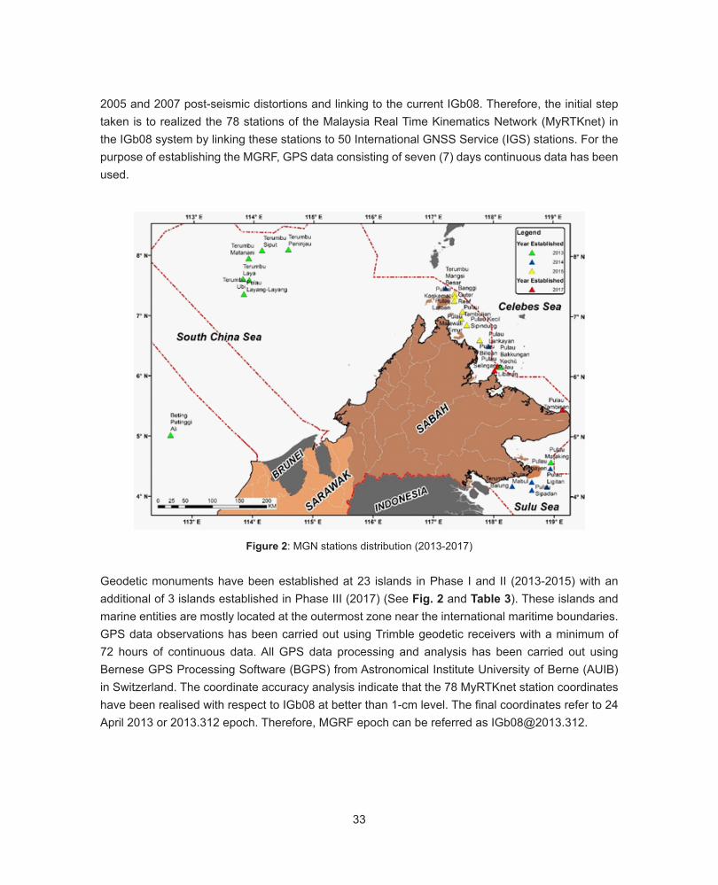
Figure 2: MGN stations distribution (2013-2017)
Geodetic monuments have been established at 23 islands in Phase I and II (2013-2015) with an additional of 3 islands established in Phase III (2017) (See Fig. 2 and Table 3). These islands and marine entities are mostly located at the outermost zone near the international maritime boundaries. GPS data observations has been carried out using Trimble geodetic receivers with a minimum of 72 hours of continuous data. All GPS data processing and analysis has been carried out using Bernese GPS Processing Software (BGPS) from Astronomical Institute University of Berne (AUIB) in Switzerland. The coordinate accuracy analysis indicate that the 78 MyRTKnet station coordinates have been realised with respect to IGb08 at better than 1-cm level. The final coordinates refer to 24 April 2013 or 2013.312 epoch. Therefore, MGRF epoch can be referred as [email protected].
34 37
have been realised with respect to IGb08 at better than 1-cm level. The final coordinates refer to 24
April 2013 or 2013.312 epoch. Therefore, MGRF epoch can be referred as [email protected].
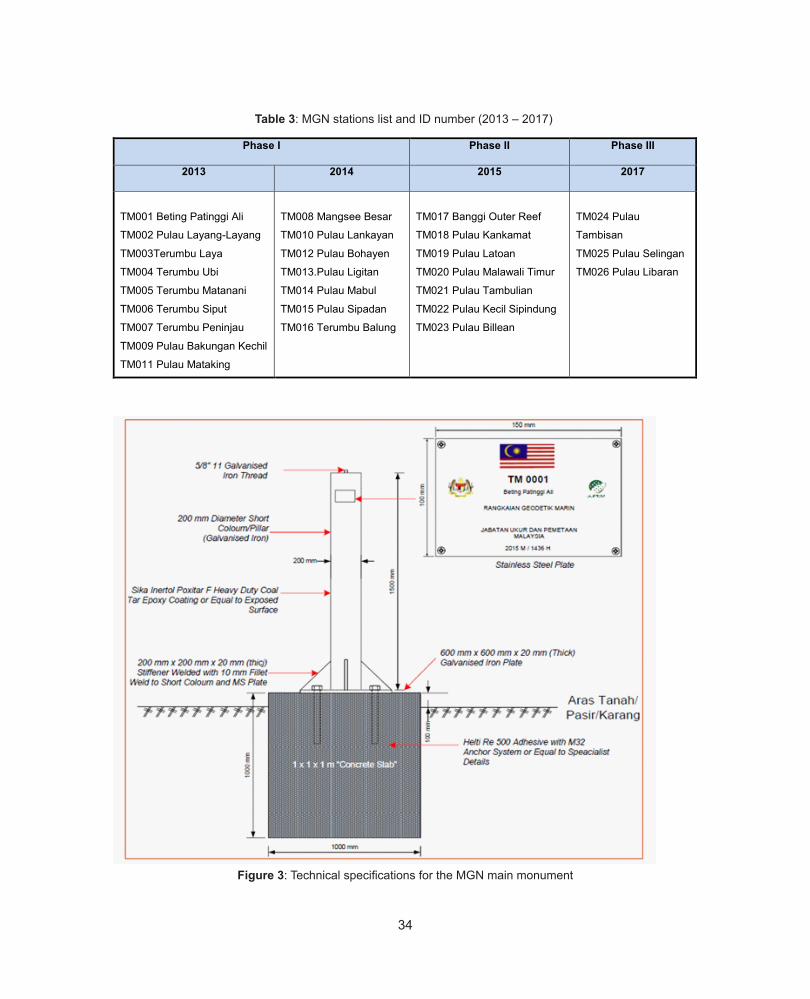
Table 3: MGN stations list and ID number (2013 – 2017)
Phase I Phase II Phase III
2013 2014 2015 2017
TM001 Beting Patinggi Ali
TM002 Pulau Layang-Layang
TM003Terumbu Laya
TM004 Terumbu Ubi
TM005 Terumbu Matanani
TM006 Terumbu Siput
TM007 Terumbu Peninjau
TM009 Pulau Bakungan Kechil
TM011 Pulau Mataking
TM008 Mangsee Besar
TM010 Pulau Lankayan
TM012 Pulau Bohayen
TM013.Pulau Ligitan
TM014 Pulau Mabul
TM015 Pulau Sipadan
TM016 Terumbu Balung
TM017 Banggi Outer Reef
TM018 Pulau Kankamat
TM019 Pulau Latoan
TM020 Pulau Malawali Timur
TM021 Pulau Tambulian
TM022 Pulau Kecil Sipindung
TM023 Pulau Billean
TM024 Pulau
Tambisan
TM025 Pulau Selingan
TM026 Pulau Libaran
Figure 3: Technical specifications for the MGN main monument
Figure 3: Technical specifications for the MGN main monument
Table 3: MGN stations list and ID number (2013 – 2017)
35
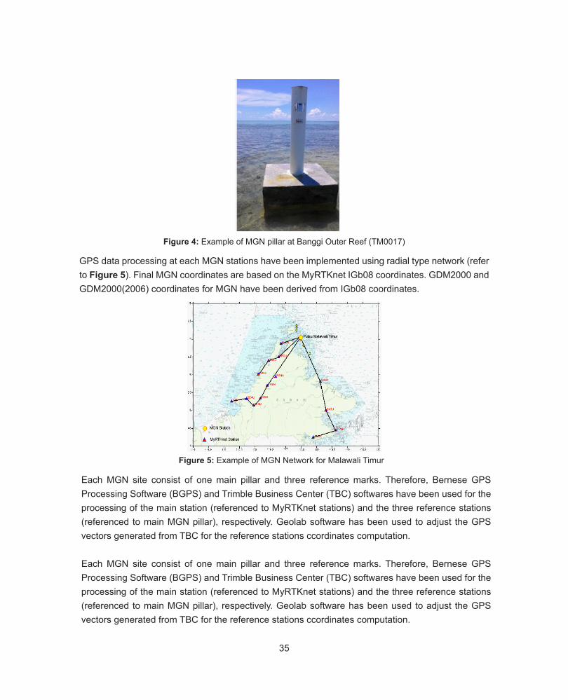
GPS data processing at each MGN stations have been implemented using radial type network (refer to Figure 5). Final MGN coordinates are based on the MyRTKnet IGb08 coordinates. GDM2000 and GDM2000(2006) coordinates for MGN have been derived from IGb08 coordinates.
Each MGN site consist of one main pillar and three reference marks. Therefore, Bernese GPS Processing Software (BGPS) and Trimble Business Center (TBC) softwares have been used for the processing of the main station (referenced to MyRTKnet stations) and the three reference stations (referenced to main MGN pillar), respectively. Geolab software has been used to adjust the GPS vectors generated from TBC for the reference stations ccordinates computation.
Each MGN site consist of one main pillar and three reference marks. Therefore, Bernese GPS Processing Software (BGPS) and Trimble Business Center (TBC) softwares have been used for the processing of the main station (referenced to MyRTKnet stations) and the three reference stations (referenced to main MGN pillar), respectively. Geolab software has been used to adjust the GPS vectors generated from TBC for the reference stations ccordinates computation.
Figure 4: Example of MGN pillar at Banggi Outer Reef (TM0017)
Figure 5: Example of MGN Network for Malawali Timur
36
3.0 THE ESTABLISHMENT OF PERMANENT ACTIVE MARINE GEODETIC GNSS STATION ON SELECTED ISLANDS OFFSHORE OF SABAH (MARINE CORS)
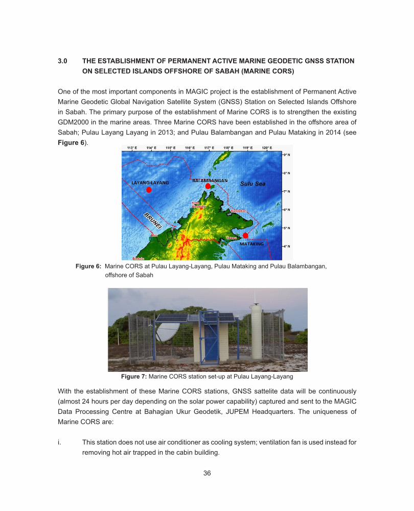
One of the most important components in MAGIC project is the establishment of Permanent Active Marine Geodetic Global Navigation Satellite System (GNSS) Station on Selected Islands Offshore in Sabah. The primary purpose of the establishment of Marine CORS is to strengthen the existing GDM2000 in the marine areas. Three Marine CORS have been established in the offshore area of Sabah; Pulau Layang Layang in 2013; and Pulau Balambangan and Pulau Mataking in 2014 (see Figure 6).
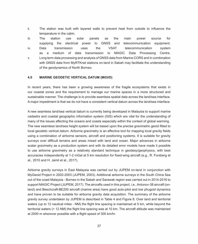
Figure 7: Marine CORS station set-up at Pulau Layang-Layang
Figure 6: Marine CORS at Pulau Layang-Layang, Pulau Mataking and Pulau Balambangan, offshore of Sabah
With the establishment of these Marine CORS stations, GNSS sattelite data will be continuously (almost 24 hours per day depending on the solar power capability) captured and sent to the MAGIC Data Processing Centre at Bahagian Ukur Geodetik, JUPEM Headquarters. The uniqueness of Marine CORS are:
i. This station does not use air conditioner as cooling system; ventilation fan is used instead for removing hot air trapped in the cabin building.
37
ii. The station was built with layered walls to prevent heat from outside to influence the temperature in the cabin.iii. The station use solar panels as the main power source for supplying the electrical power to GNSS and telecommunication equipment. iv. Data transmission uses the VSAT telecommunication system as a medium of data transmission to MAGIC Data Processing Centre. v. Long term data processing and analysis of GNSS data from Marine CORS and in combination with GNSS data from MyRTKnet stations on-land in Sabah may facilitate the understanding of the geodynamics of North Borneo.
4.0 MARINE GEODETIC VERTICAL DATUM (MGVD)
In recent years, there has been a growing awareness of the fragile ecosystems that exists in our coastal zones and the requirement to manage our marine spaces in a more structured and sustainable manner. The challenge is to provide seamless spatial data across the land/sea interface. A major impediment is that we do not have a consistent vertical datum across the land/sea interface.
A new seamless land/sea vertical datum is currently being developed in Malaysia to support marine cadastre and coastal geographic information system (GIS) which are vital for the understanding of many of the issues affecting the oceans and coasts especially within the context of global warming. The new seamless land/sea height system will be based upon the precise gravimetric geoid fitted to local geodetic vertical datum. Airborne gravimetry is an effective tool for mapping local gravity fields using a combination of airborne sensors, aircraft and positioning systems. It is suitable for gravity surveys over difficult terrains and areas mixed with land and ocean. Major advances in airborne scalar gravimetry as a production system and with its detailed error models have made it possible to use airborne gravimetry as a relatively standard technique in geodesy/geophysics, with best accuracies independently at 1-2 mGal at 5 km resolution for fixed-wing aircraft (e.g., R. Forsberg et al., 2010 and H. Jamil et al., 2017).
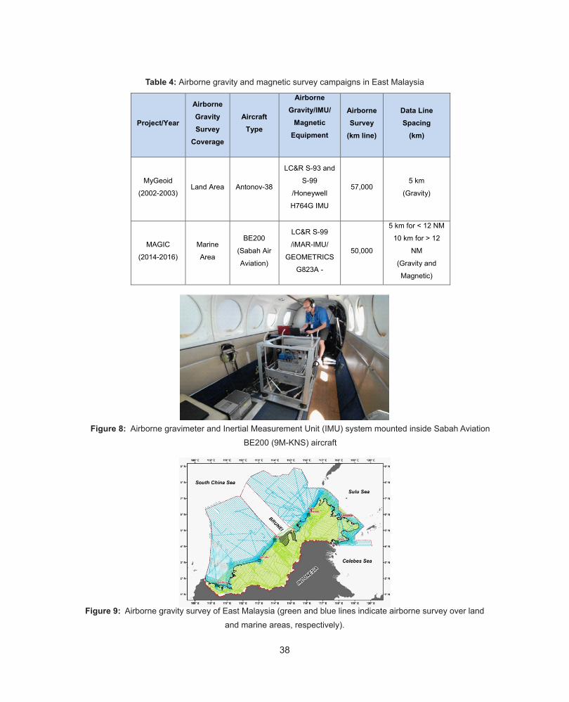
Airborne gravity surveys in East Malaysia was carried out by JUPEM on-land in conjunction with MyGeoid Project in 2002-2003 (JUPEM, 2003). Additional airborne surveys in the South China Sea out of the coast Malaysia - Borneo in the Sabah and Sarawak region was carried out in 2014-2016 tosupport MAGIC Project (JUPEM, 2017). The aircrafts used in this project, i.e., Antonov-38 aircraft (on-land) and Beechcraft-BE200 aircraft (marine area) have good auto-pilot and low phugoid dynamics and have proven to be suitable for airborne gravity data acquisition. The summary of the airborne gravity survey undertaken by JUPEM is described in Table 4 and Figure 8. Over land and territorial waters (up to 12 nautical miles - NM) the flight line spacing is maintained at 5 km, while beyond the territorial waters (> 12 NM) the flight line spacing was at 10 km. The aircraft altitude was maintained at 2000 m wherever possible with a flight speed of 300 km/hr.
38
41
A new seamless land/sea vertical datum is currently being developed in Malaysia to support marine
cadastre and coastal geographic information system (GIS) which are vital for the understanding of
many of the issues affecting the oceans and coasts especially within the context of global warming.
The new seamless land/sea height system will be based upon the precise gravimetric geoid fitted to
local geodetic vertical datum. Airborne gravimetry is an effective tool for mapping local gravity fields
using a combination of airborne sensors, aircraft and positioning systems. It is suitable for gravity
surveys over difficult terrains and areas mixed with land and ocean. Major advances in airborne
scalar gravimetry as a production system and with its detailed error models have made it possible to
use airborne gravimetry as a relatively standard technique in geodesy/geophysics, with best
accuracies independently at 1-2 mGal at 5 km resolution for fixed-wing aircraft (e.g., R. Forsberg et
al., 2010 and H. Jamil et al., 2017).
Airborne gravity surveys in East Malaysia was carried out by JUPEM on-land in conjunction with
MyGeoid Project in 2002-2003 (JUPEM, 2003). Additional airborne surveys in the South China Sea
out of the coast Malaysia - Borneo in the Sabah and Sarawak region was carried out in 2014-2016
to support MAGIC Project (JUPEM, 2017). The aircrafts used in this project, i.e., Antonov-38 aircraft
(on-land) and Beechcraft-BE200 aircraft (marine area) have good auto-pilot and low phugoid
dynamics and have proven to be suitable for airborne gravity data acquisition. The summary of the
airborne gravity survey undertaken by JUPEM is described in Table 4 and Figure 8. Over land and
territorial waters (up to 12 nautical miles - NM) the flight line spacing is maintained at 5 km, while
beyond the territorial waters (> 12 NM) the flight line spacing was at 10 km. The aircraft altitude was
maintained at 2000 m wherever possible with a flight speed of 300 km/hr.
Table 4: Airborne gravity and magnetic survey campaigns in East Malaysia
Project/Year
Airborne Gravity Survey
Coverage
Aircraft Type
Airborne Gravity/IMU/
Magnetic Equipment
Airborne Survey
(km line)
Data Line Spacing
(km)
MyGeoid
(2002-2003) Land Area Antonov-38
LC&R S-93 and
S-99
/Honeywell
H764G IMU
57,000 5 km
(Gravity)
MAGIC
(2014-2016)
Marine
Area
BE200
(Sabah Air
Aviation)
LC&R S-99
/iMAR-IMU/ GEOMETRICS
G823A -
50,000
5 km for < 12 NM
10 km for > 12
NM
(Gravity and
Magnetic)
Figure 8: Airborne gravimeter and Inertial Measurement Unit (IMU) system mounted inside Sabah Aviation BE200 (9M-KNS) aircraft
Figure 9: Airborne gravity survey of East Malaysia (green and blue lines indicate airborne survey over land and marine areas, respectively).
Table 4: Airborne gravity and magnetic survey campaigns in East Malaysia
39
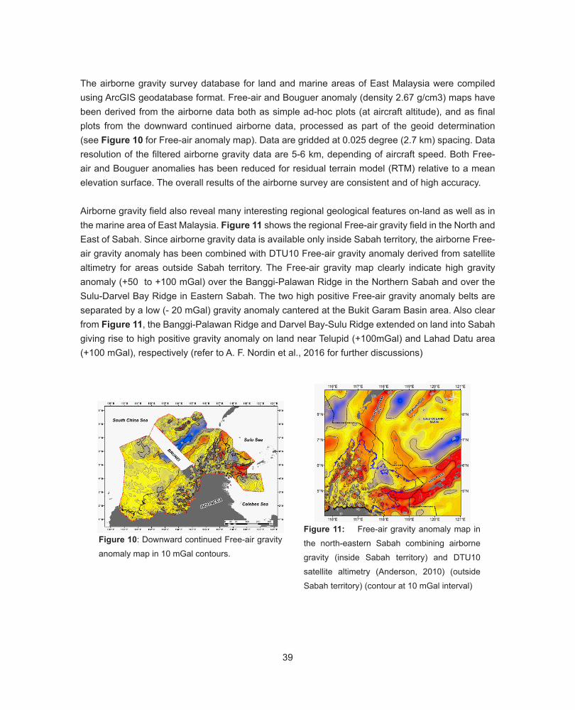
The airborne gravity survey database for land and marine areas of East Malaysia were compiled using ArcGIS geodatabase format. Free-air and Bouguer anomaly (density 2.67 g/cm3) maps have been derived from the airborne data both as simple ad-hoc plots (at aircraft altitude), and as final plots from the downward continued airborne data, processed as part of the geoid determination (see Figure 10 for Free-air anomaly map). Data are gridded at 0.025 degree (2.7 km) spacing. Data resolution of the filtered airborne gravity data are 5-6 km, depending of aircraft speed. Both Free-air and Bouguer anomalies has been reduced for residual terrain model (RTM) relative to a mean elevation surface. The overall results of the airborne survey are consistent and of high accuracy.
Airborne gravity field also reveal many interesting regional geological features on-land as well as in the marine area of East Malaysia. Figure 11 shows the regional Free-air gravity field in the North and East of Sabah. Since airborne gravity data is available only inside Sabah territory, the airborne Free-air gravity anomaly has been combined with DTU10 Free-air gravity anomaly derived from satellite altimetry for areas outside Sabah territory. The Free-air gravity map clearly indicate high gravity anomaly (+50 to +100 mGal) over the Banggi-Palawan Ridge in the Northern Sabah and over the Sulu-Darvel Bay Ridge in Eastern Sabah. The two high positive Free-air gravity anomaly belts are separated by a low (- 20 mGal) gravity anomaly cantered at the Bukit Garam Basin area. Also clear from Figure 11, the Banggi-Palawan Ridge and Darvel Bay-Sulu Ridge extended on land into Sabah giving rise to high positive gravity anomaly on land near Telupid (+100mGal) and Lahad Datu area (+100 mGal), respectively (refer to A. F. Nordin et al., 2016 for further discussions)
Figure 10: Downward continued Free-air gravity anomaly map in 10 mGal contours.
Figure 11: Free-air gravity anomaly map in the north-eastern Sabah combining airborne gravity (inside Sabah territory) and DTU10 satellite altimetry (Anderson, 2010) (outside Sabah territory) (contour at 10 mGal interval)
40
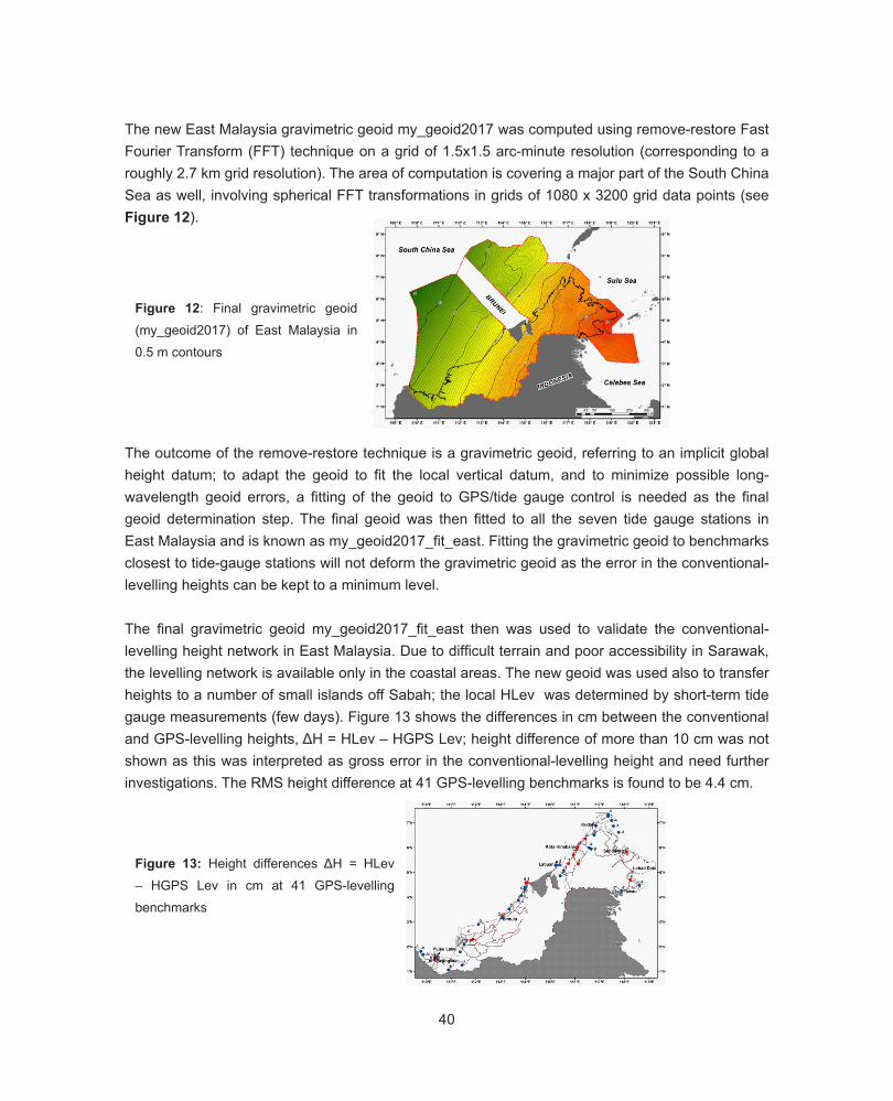
The new East Malaysia gravimetric geoid my_geoid2017 was computed using remove-restore Fast Fourier Transform (FFT) technique on a grid of 1.5x1.5 arc-minute resolution (corresponding to a roughly 2.7 km grid resolution). The area of computation is covering a major part of the South China Sea as well, involving spherical FFT transformations in grids of 1080 x 3200 grid data points (see Figure 12).
Figure 12: Final gravimetric geoid (my_geoid2017) of East Malaysia in 0.5 m contours
The outcome of the remove-restore technique is a gravimetric geoid, referring to an implicit global height datum; to adapt the geoid to fit the local vertical datum, and to minimize possible long-wavelength geoid errors, a fitting of the geoid to GPS/tide gauge control is needed as the final geoid determination step. The final geoid was then fitted to all the seven tide gauge stations in East Malaysia and is known as my_geoid2017_fit_east. Fitting the gravimetric geoid to benchmarks closest to tide-gauge stations will not deform the gravimetric geoid as the error in the conventional-levelling heights can be kept to a minimum level.
The final gravimetric geoid my_geoid2017_fit_east then was used to validate the conventional-levelling height network in East Malaysia. Due to difficult terrain and poor accessibility in Sarawak, the levelling network is available only in the coastal areas. The new geoid was used also to transfer heights to a number of small islands off Sabah; the local HLev was determined by short-term tide gauge measurements (few days). Figure 13 shows the differences in cm between the conventional and GPS-levelling heights, ΔH = HLev – HGPS Lev; height difference of more than 10 cm was not shown as this was interpreted as gross error in the conventional-levelling height and need further investigations. The RMS height difference at 41 GPS-levelling benchmarks is found to be 4.4 cm.
Figure 13: Height differences ΔH = HLev – HGPS Lev in cm at 41 GPS-levelling benchmarks
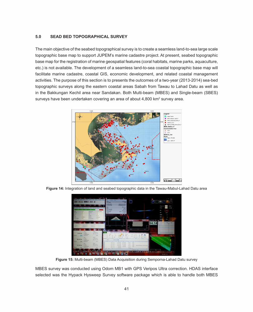
41
5.0 SEAD BED TOPOGRAPHICAL SURVEY
The main objective of the seabed topographical survey is to create a seamless land-to-sea large scale topographic base map to support JUPEM’s marine cadastre project. At present, seabed topographic base map for the registration of marine geospatial features (coral habitats, marine parks, aquaculture, etc.) is not available. The development of a seamless land-to-sea coastal topographic base map will facilitate marine cadastre, coastal GIS, economic development, and related coastal management activities. The purpose of this section is to presents the outcomes of a two-year (2013-2014) sea-bed topographic surveys along the eastern coastal areas Sabah from Tawau to Lahad Datu as well as in the Bakkungan Kechil area near Sandakan. Both Multi-beam (MBES) and Single-beam (SBES) surveys have been undertaken covering an area of about 4,800 km2 survey area.
Figure 14: Integration of land and seabed topographic data in the Tawau-Mabul-Lahad Datu area
MBES survey was conducted using Odom MB1 with GPS Veripos Ultra correction. HDAS interface selected was the Hypack Hysweep Survey software package which is able to handle both MBES
Figure 15: Multi-beam (MBES) Data Acquisition during Semporna-Lahad Datu survey
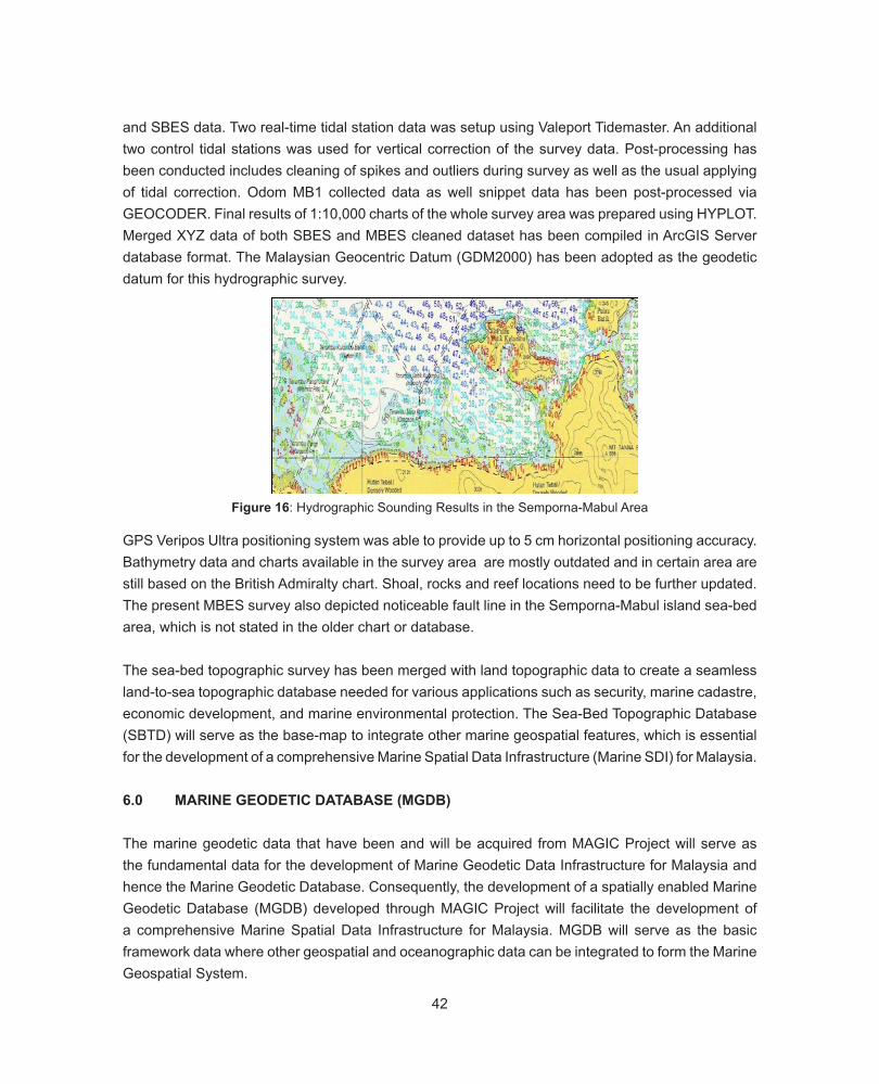
42
and SBES data. Two real-time tidal station data was setup using Valeport Tidemaster. An additional two control tidal stations was used for vertical correction of the survey data. Post-processing has been conducted includes cleaning of spikes and outliers during survey as well as the usual applying of tidal correction. Odom MB1 collected data as well snippet data has been post-processed via GEOCODER. Final results of 1:10,000 charts of the whole survey area was prepared using HYPLOT. Merged XYZ data of both SBES and MBES cleaned dataset has been compiled in ArcGIS Server database format. The Malaysian Geocentric Datum (GDM2000) has been adopted as the geodetic datum for this hydrographic survey.
Figure 16: Hydrographic Sounding Results in the Semporna-Mabul Area
GPS Veripos Ultra positioning system was able to provide up to 5 cm horizontal positioning accuracy. Bathymetry data and charts available in the survey area are mostly outdated and in certain area are still based on the British Admiralty chart. Shoal, rocks and reef locations need to be further updated. The present MBES survey also depicted noticeable fault line in the Semporna-Mabul island sea-bed area, which is not stated in the older chart or database.
The sea-bed topographic survey has been merged with land topographic data to create a seamless land-to-sea topographic database needed for various applications such as security, marine cadastre, economic development, and marine environmental protection. The Sea-Bed Topographic Database (SBTD) will serve as the base-map to integrate other marine geospatial features, which is essential for the development of a comprehensive Marine Spatial Data Infrastructure (Marine SDI) for Malaysia.
6.0 MARINE GEODETIC DATABASE (MGDB)
The marine geodetic data that have been and will be acquired from MAGIC Project will serve as the fundamental data for the development of Marine Geodetic Data Infrastructure for Malaysia and hence the Marine Geodetic Database. Consequently, the development of a spatially enabled Marine Geodetic Database (MGDB) developed through MAGIC Project will facilitate the development of a comprehensive Marine Spatial Data Infrastructure for Malaysia. MGDB will serve as the basic framework data where other geospatial and oceanographic data can be integrated to form the Marine Geospatial System.
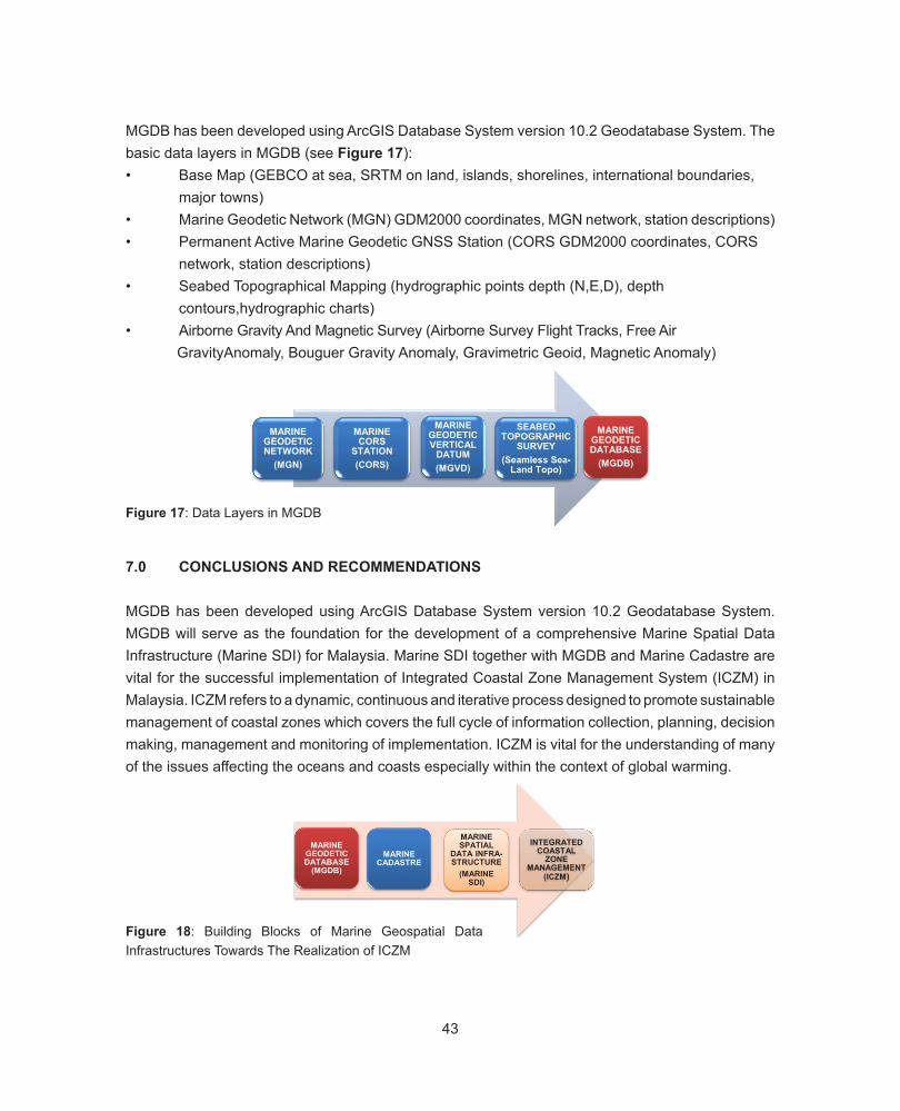
43
MGDB has been developed using ArcGIS Database System version 10.2 Geodatabase System. The basic data layers in MGDB (see Figure 17):• Base Map (GEBCO at sea, SRTM on land, islands, shorelines, international boundaries,
major towns)• Marine Geodetic Network (MGN) GDM2000 coordinates, MGN network, station descriptions)• Permanent Active Marine Geodetic GNSS Station (CORS GDM2000 coordinates, CORS
network, station descriptions)• Seabed Topographical Mapping (hydrographic points depth (N,E,D), depth
contours,hydrographic charts)• Airborne Gravity And Magnetic Survey (Airborne Survey Flight Tracks, Free Air
GravityAnomaly, Bouguer Gravity Anomaly, Gravimetric Geoid, Magnetic Anomaly)
Figure 17: Data Layers in MGDB
7.0 CONCLUSIONS AND RECOMMENDATIONS
MGDB has been developed using ArcGIS Database System version 10.2 Geodatabase System. MGDB will serve as the foundation for the development of a comprehensive Marine Spatial Data Infrastructure (Marine SDI) for Malaysia. Marine SDI together with MGDB and Marine Cadastre are vital for the successful implementation of Integrated Coastal Zone Management System (ICZM) in Malaysia. ICZM refers to a dynamic, continuous and iterative process designed to promote sustainable management of coastal zones which covers the full cycle of information collection, planning, decision making, management and monitoring of implementation. ICZM is vital for the understanding of many of the issues affecting the oceans and coasts especially within the context of global warming.48
the Marine Geodetic Database. Consequently, the development of a spatially enabled Marine
Geodetic Database (MGDB) developed through MAGIC Project will facilitate the development of a
comprehensive Marine Spatial Data Infrastructure for Malaysia. MGDB will serve as the basic
framework data where other geospatial and oceanographic data can be integrated to form the Marine
Geospatial System.
MGDB has been developed using ArcGIS Database System version 10.2 Geodatabase System. The
basic data layers in MGDB (see Figure 17):
Base Map (GEBCO at sea, SRTM on land, islands, shorelines, international boundaries,
major towns)
Marine Geodetic Network (MGN) GDM2000 coordinates, MGN network, station
descriptions)
Permanent Active Marine Geodetic GNSS Station (CORS GDM2000 coordinates, CORS
network, station descriptions)
Seabed Topographical Mapping (hydrographic points depth (N,E,D), depth contours,
hydrographic charts)
Airborne Gravity And Magnetic Survey (Airborne Survey Flight Tracks, Free Air Gravity
Anomaly, Bouguer Gravity Anomaly, Gravimetric Geoid, Magnetic Anomaly)
Figure 17: Data Layers in MGDB
7.0 CONCLUSIONS AND RECOMMENDATIONS MGDB has been developed using ArcGIS Database System version 10.2 Geodatabase System.
MGDB will serve as the foundation for the development of a comprehensive Marine Spatial Data
Infrastructure (Marine SDI) for Malaysia. Marine SDI together with MGDB and Marine Cadastre are
vital for the successful implementation of Integrated Coastal Zone Management System (ICZM) in
Malaysia. ICZM refers to a dynamic, continuous and iterative process designed to promote
sustainable management of coastal zones which covers the full cycle of information collection,
planning, decision making, management and monitoring of implementation. ICZM is vital for the
understanding of many of the issues affecting the oceans and coasts especially within the context of
global warming.
MARINE GEODETIC NETWORK
(MGN)
MARINE CORS
STATION(CORS)
MARINE GEODETIC VERTICAL
DATUM(MGVD)
SEABED TOPOGRAPHIC
SURVEY(Seamless Sea-
Land Topo)
MARINE GEODETIC DATABASE
(MGDB)
Figure 18: Building Blocks of Marine Geospatial Data Infrastructures Towards The Realization of ICZM
49
Figure 18: Building Blocks of Marine Geospatial Data Infrastructures Towards The Realization of ICZM
The following further works are recommended:
i. Continental shelf map series (gravity, magnetic and seabed topography) for East Malaysia
should be produced to support sovereignty issue in the South China Sea.
ii. Seabed topographic mapping should be implemented in coastal zone areas to support
marine cadastre, economic development, national security and issues related to coastal
erosion due to global warming. Coastal topographic map series should include both land and
seabed topography.
iii. MAGIC Project should be implemented in Peninsula Malaysia waters.
ACKNOWLEDGEMENT
We would like to record our gratitude to the Ministry of Natural Resources and Environment (NRE)
Malaysia for the support given during the implementation of the Marine Geodetic Infrastructures in
Malaysian Waters (MAGIC).The cooperation from Bahagian Geospatial Pertahanan (BGSP/JUPEM)
and Kawasan Keselamatan Khas Pantai Timur Sabah (ESSCOM) for the security arrangements are
greatly appreciated.
MARINE GEODETIC DATABASE
(MGDB)
MARINE CADASTRE
MARINE SPATIAL
DATA INFRA-STRUCTURE
(MARINE SDI)
INTEGRATED COASTAL
ZONE MANAGEMENT
(ICZM)
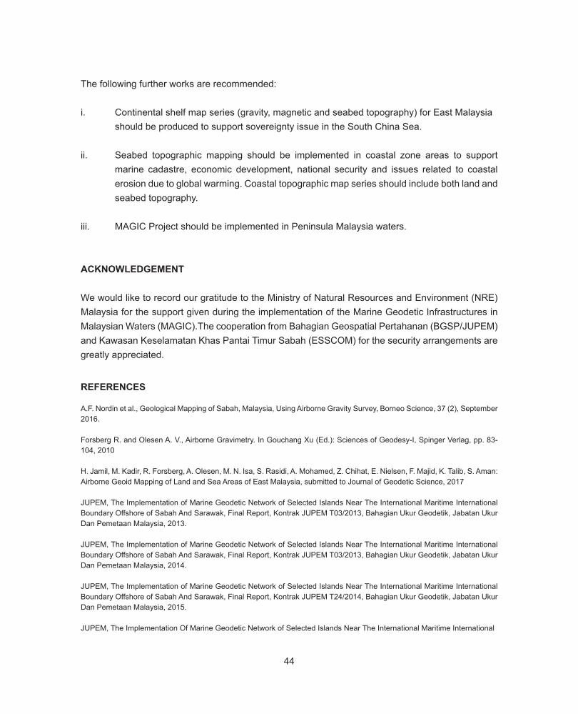
44
The following further works are recommended:
i. Continental shelf map series (gravity, magnetic and seabed topography) for East Malaysia should be produced to support sovereignty issue in the South China Sea.
ii. Seabed topographic mapping should be implemented in coastal zone areas to support marine cadastre, economic development, national security and issues related to coastal erosion due to global warming. Coastal topographic map series should include both land and seabed topography.
iii. MAGIC Project should be implemented in Peninsula Malaysia waters.
ACKNOWLEDGEMENT
We would like to record our gratitude to the Ministry of Natural Resources and Environment (NRE) Malaysia for the support given during the implementation of the Marine Geodetic Infrastructures in Malaysian Waters (MAGIC).The cooperation from Bahagian Geospatial Pertahanan (BGSP/JUPEM) and Kawasan Keselamatan Khas Pantai Timur Sabah (ESSCOM) for the security arrangements are greatly appreciated.
REFERENCES
A.F. Nordin et al., Geological Mapping of Sabah, Malaysia, Using Airborne Gravity Survey, Borneo Science, 37 (2), September 2016.
Forsberg R. and Olesen A. V., Airborne Gravimetry. In Gouchang Xu (Ed.): Sciences of Geodesy-I, Spinger Verlag, pp. 83-104, 2010
H. Jamil, M. Kadir, R. Forsberg, A. Olesen, M. N. Isa, S. Rasidi, A. Mohamed, Z. Chihat, E. Nielsen, F. Majid, K. Talib, S. Aman: Airborne Geoid Mapping of Land and Sea Areas of East Malaysia, submitted to Journal of Geodetic Science, 2017
JUPEM, The Implementation of Marine Geodetic Network of Selected Islands Near The International Maritime International Boundary Offshore of Sabah And Sarawak, Final Report, Kontrak JUPEM T03/2013, Bahagian Ukur Geodetik, Jabatan Ukur Dan Pemetaan Malaysia, 2013.
JUPEM, The Implementation of Marine Geodetic Network of Selected Islands Near The International Maritime International Boundary Offshore of Sabah And Sarawak, Final Report, Kontrak JUPEM T03/2013, Bahagian Ukur Geodetik, Jabatan Ukur Dan Pemetaan Malaysia, 2014.
JUPEM, The Implementation of Marine Geodetic Network of Selected Islands Near The International Maritime International Boundary Offshore of Sabah And Sarawak, Final Report, Kontrak JUPEM T24/2014, Bahagian Ukur Geodetik, Jabatan Ukur Dan Pemetaan Malaysia, 2015.
JUPEM, The Implementation Of Marine Geodetic Network of Selected Islands Near The International Maritime International

45
Boundary Offshore of Sabah And Sarawak, Final Report, Kontrak JUPEM T09/2017, Bahagian Ukur Geodetik, Jabatan Ukur Dan Pemetaan Malaysia, 2017.
JUPEM, The Establishment of Permanent Active Marine Geodetic GNSS Station On Selected Island Offshore of Sabah: Pulau Layang-Layang, Final Report, Kontrak JUPEM T03/2013, Bahagian Ukur Geodetik, Jabatan Ukur Dan Pemetaan Malaysia, 2013.
JUPEM, The Establishment of Permanent Active Marine Geodetic GNSS Station On Selected Island Offshore of Sabah: Pulau Balambangan And Pulau Mataking, Final Report, Kontrak JUPEM T03/2013, Bahagian Ukur Geodetik, Jabatan Ukur Dan Pemetaan Malaysia, 2014.
JUPEM, Airborne Gravity Survey and Geoid Determination Project For Peninsular Malaysia, Sabah And Sarawak, Final Report, Seksyen Ukur Geodetik, Jabatan Ukur Dan Pemetaan Malaysia, 2003.
JUPEM, The Conduct of Airborne Gravity And Magnetic Survey Over Selected Area Near The International Maritime Boundary Offshore of Sabah And Sarawak: Completion of Phase I, II And III (2014-2017), Final Report, Kontrak JUPEM T09/2016, Bahagian Ukur Geodetik, Jabatan Ukur Dan Pemetaan Malaysia, 2017.
JUPEM, The Conduct of Seabed Topographical Survey Around Selected Islands Near The International Maritime Boundary Offshore of Sabah: Bakkungan Kechil, Final Report, Kontrak JUPEM T03/2013, Bahagian Ukur Geodetik, Jabatan Ukur Dan Pemetaan Malaysia, 2013.
JUPEM, The Conduct of Seabed Topographical Survey Around Selected Islands Near The International Maritime Boundary Offshore of Sabah: Tawau-Semporna-Lahad Datu, Final Report, Kontrak JUPEM T03/2013, Bahagian Ukur Geodetik, Jabatan Ukur Dan Pemetaan Malaysia, 2014.
JUPEM, The Development of Marine Geodetic Processing Centre and Database Including Further Refinement, Customization and Operation At Jupem Headquarters, Kuala Lumpur, Final Report, Kontrak JUPEM T03/2013, Bahagian Ukur Geodetik, Jabatan Ukur Dan Pemetaan Malaysia, 2013-2014.
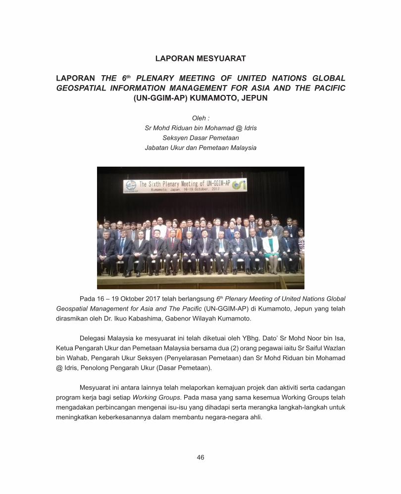
46
LAPORAN MESYUARAT
LAPORAN THE 6th PLENARY MEETING OF UNITED NATIONS GLOBAL GEOSPATIAL INFORMATION MANAGEMENT FOR ASIA AND THE PACIFIC
(UN-GGIM-AP) KUMAMOTO, JEPUN
Oleh :Sr Mohd Riduan bin Mohamad @ Idris
Seksyen Dasar PemetaanJabatan Ukur dan Pemetaan Malaysia
Pada 16 – 19 Oktober 2017 telah berlangsung 6th Plenary Meeting of United Nations Global Geospatial Management for Asia and The Pacific (UN-GGIM-AP) di Kumamoto, Jepun yang telah dirasmikan oleh Dr. Ikuo Kabashima, Gabenor Wilayah Kumamoto.
Delegasi Malaysia ke mesyuarat ini telah diketuai oleh YBhg. Dato’ Sr Mohd Noor bin Isa, Ketua Pengarah Ukur dan Pemetaan Malaysia bersama dua (2) orang pegawai iaitu Sr Saiful Wazlan bin Wahab, Pengarah Ukur Seksyen (Penyelarasan Pemetaan) dan Sr Mohd Riduan bin Mohamad @ Idris, Penolong Pengarah Ukur (Dasar Pemetaan).
Mesyuarat ini antara lainnya telah melaporkan kemajuan projek dan aktiviti serta cadangan program kerja bagi setiap Working Groups. Pada masa yang sama kesemua Working Groups telah mengadakan perbincangan mengenai isu-isu yang dihadapi serta merangka langkah-langkah untuk meningkatkan keberkesanannya dalam membantu negara-negara ahli.
47
Sempena dengan mesyuarat ini juga telah diadakan satu sesi khas iaitu Gesopatial Information for Disaster Response – Case study on the Disaster Response for Kumamoto Earthquake in April 2016 yang membincangkan berkenaan kepentingan maklumat geospatial dalam pengurusan bencana dengan mengambil kajian kes kejadian gempa bumi yang berlaku di Kumamoto, Jepun pada bulan April 2016.
Di akhir mesyuarat tersebut beberapa resolusi telah dicapai yang antara lainnya adalah seperti berikut:
a) Menggalakkan perlaksanaan strategi dan polisi bagi data geodetik serta memastikan ianya selari dengan UN-GGIM Working Group on Legal and Policy Frameworks for Geospatial Management;
b) Menggalakkan perkongsian data geodetik bagi menyokong International Terrestial Reference Frame (ITRF) dan program-program geodetik serantau seperti Asia Pacific Regional Reference Frame (APREF), Asia Pacific Regional Geodetic Project (APRGP) serta penyeragaman sistem-sistem ketinggian;
c) Menghimpunkan koleksi amalan terbaik penggunaan maklumat geospatial bagi pengurangan risiko bencana di wilayah Asia Pasifik;
d) Mengadakan mesyuarat kumpulan kerja untuk membincangkan deraf model konseptual kadaster dan pengurusan tanah yang bersesuaian untuk wilayah Asia Pasifik serta memperbaiki dan memperhalusinya. Deraf yang telah diperhalusi ini seterusnya akan dibentangkan kepada negara-negara ahli bagi mendapatkan pandangan yang lebih luas berkenaan deraf model konseptual yang disediakan.
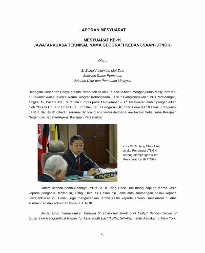
48
LAPORAN MESYUARAT
MESYUARAT KE-19JAWATANKUASA TEKNIKAL NAMA GEOGRAFI KEBANGSAAN (JTNGK)
Oleh :
Sr Zainal Abidin bin Mat ZainSeksyen Dasar Pemetaan
Jabatan Ukur dan Pemetaan Malaysia
Bahagian Dasar dan Penyelarasan Pemetaan selaku urus setia telah menganjurkan Mesyuarat Ke-19 Jawatankuasa Teknikal Nama Geografi Kebangsaan (JTNGK) yang diadakan di Bilik Persidangan, Tingkat 15, Wisma JUPEM, Kuala Lumpur pada 1 November 2017. Mesyuarat telah dipengerusikan oleh YBrs Sr Dr. Teng Chee Hua, Timbalan Ketua Pengarah Ukur dan Pemetaan II selaku Pengerusi JTNGK dan telah dihadiri seramai 32 orang ahli terdiri daripada wakil-wakil Setiausaha Kerajaan Negeri dan Jabatan/Agensi Kerajaan Persekutuan.
Dalam ucapan pembukaannya, YBrs Sr Dr. Teng Chee Hua mengucapkan terima kasih kepada pengerusi terdahulu, YBhg. Dato’ Sr Hasan bin Jamil atas sumbangan beliau kepada Jawatankuasa ini. Beliau juga mengucapkan terima kasih kepada ahli-ahli mesyuarat di atas sumbangan dan sokongan kepada JTNGK.
Beliau turut memaklumkan bahawa 5th Divisional Meeting of United Nations Group of Experts on Geographical Names for Asia South East (UNGEGN-ASE) telah diadakan di New York,
YBrs Sr Dr. Teng Chee Hua selaku Pengerusi JTNGK sedang mempengerusikan Mesyuarat Ke-19 JTNGK
49
Amerika Syarikat pada 9 Ogos 2017 yang lalu. Mesyuarat ini telah dihadiri oleh Sr Dr. Zainal bin A Majeed, Pengarah Ukur dan Pemetaan Selangor selaku wakil Malaysia dan turut dihadiri oleh lima (5) buah negara anggota lain iaitu Brunei Darussalam, Indonesia, Filipina, Singapura dan Vietnam. Dalam masa yang sama, Sr Dr. Zainal bin A Majeed juga telah menghadiri 11th United Nations Conference on the Standardization of Geographical Names (UNCSGN) yang juga diadakan di New York pada 8-17 Ogos 2017.
Beliau turut menyentuh berkenaan PDNG Fasa III yang akan dilaksanakan berdasarkan Standard Operating Procedure (SOP) Pangkalan Data Nama Geografi Dan Gazetir Kebangsaan (PDNG) Fasa III seperti yang telah dibincangkan semasa Mesyuarat Penyediaan SOP pada 23 hingga 25 Mei 2017 di George Town, Pulau Pinang. Akhir sekali, beliau menegaskan kerjasama dan sokongan sepenuhnya amat diperlukan daripada urus setia dan juga pihak negeri yang terlibat bagi menjayakan PDNG Fasa III ini.
Ahli-ahli mesyuarat menyuarakan pendapat serta memberikan penumpuan sepenuhnya semasa mesyuarat berlangsung
Sr Zulkifli bin Sidek selaku Pengerusi KKDPNG (kanan), Sr Hj. Ahmad Akhir bin Tompang wakil Pengerusi KKPDNG (tengah) dan Lt. Kdr Khairie bin Hatun, TLDM wakil Pengerusi KKNPEG (kiri)
50
Laporan Kumpulan-Kumpulan Kerja
Antara agenda mesyuarat pada kali ini adalah pembentangan laporan ringkas daripada tiga (3) Kumpulan Kerja yang membantu JTNGK dalam menggerakkan aktivitinya. Kumpulan-kumpulan kerja yang tersebut adalah seperti berikut:
i. Kumpulan Kerja Dasar dan Pengemaskinian Nama Geografi (KKDPNG) Pengerusi: Jabatan Ukur dan Pemetaan Malaysia (JUPEM)
ii. Kumpulan Kerja Pangkalan Data Nama Geografi dan Gazetir Kebangsaan (KKPDNG) Pengerusi: Pusat Infrastruktur Data Geospatial Negara (MaCGDI)
iii. Kumpulan Kerja Nama Pulau dan Entiti Geografi (KKNPEG) Pengerusi: Pusat Hidrografi Nasional (PHN)
Daripada pembentangan-pembentangan tersebut, terdapat beberapa isu yang perlu diselesaikan dan perkara ini memerlukan kerjasama dari semua pihak. Ahli-ahli mesyuarat juga turut memberikan input bagi membantu menyelesaikan isu-isu tersebut.
Antara barisan ahli mesyuarat yang hadir
51
Kesimpulan
Melalui Jawatankuasa ini, pelbagai perkara berbangkit diperingkat Kumpulan Kerja dapat dibincangkan dan diselesaikan terutamanya dalam memastikan penyelarasan bagi nama-nama geografi di Malaysia.
Kesemua ahli mesyuarat bergambar kenang-kenangan
52
LAPORAN MESYUARAT
MESYUARAT JAWATANKUASA PENYELARAS PENGGAMBARAN DAN PENGIMEJAN UDARA BAGI AGENSI-AGENSI DI BAWAH NRE (JPPPNRE)
BIL. 2/2017
Oleh :
Sr Mohd Riduan bin Mohamad @ IdrisSeksyen Dasar Pemetaan
Jabatan Ukur dan Pemetaan Malaysia
J a w a t a n k u a s a Penyelaras Penggambaran dan Pengimejan Udara Bagi Agensi-Agensi di Bawah NRE (JPPPNRE) telah mengadakan mesyuarat JPPPNRE Bilangan 2 Tahun 2017 pada 29 November 2017 bertempat di Bilik Mesyuarat Permata, Kementerian Sumber Asli dan Alam Sekitar, Putrajaya. Mesyuarat ini telah dipengerusikan oleh YBhg. Dato’ Haji Suhaimi bin Mamat, Timbalan Ketua Setiausaha (Sumber Asli), Kementerian Sumber Asli dan Alam Sekitar (NRE) dan telah dihadiri oleh pegawai daripada semua jabatan di bawah NRE.
JPPPNRE dahulunya dikenali sebagai Jawatankuasa Penyelaras Penggunaan Drone Bagi Agensi-Agensi di Bawah NRE (JPPDNRE) yang hanya menyelaras aktiviti berkaitan penggunaan drone oleh agensi-agensi di bawah NRE. Namun begitu, Mesyuarat JPPDNRE Bilangan 1 Tahun 2017 pada 16 Februari 2017 telah memutuskan agar fungsi dan skop jawatankuasa ini diperluaskan bagi menyelaras sebarang aktiviti penggambaran dan pengimejan udara yang tidak hanya terhad kepada penggunaan drone sahaja dan dikenali sebagai JPPPNRE.

53
Mesyuarat ini telah membincangkan perlbagai perkara yang berkaitan aktiviti dan penyelarasan aktiviti penggambaran dan pengimejan dikalangan agensi-agensi di bawah NRE yang antara lainnya adalah seperti berikut:
a. Pekeliling dan garis panduan terkini berkaitan aktiviti penggambaran dan pengimejan udara; b. Aktiviti-aktiviti penggunaan drone oleh agensi-agensi di bawah NRE; c. Penubuhan Fleet Commander Drone; d. Pindaan kepada surat Pekeliling KSU NRE Bilangan 1 Tahun 2015 - Garis Panduan Urusan Penyelarasan Penggambaran dan Pengimejan Dari Udara Menggunakan Drone Bagi Agensi-Agensi di Bawah NRE; dan e. Permohonan kelulusan aktiviti citraan udara
Antara ahli-ahli mesyuarat JPPPNRE Bil.2/2017
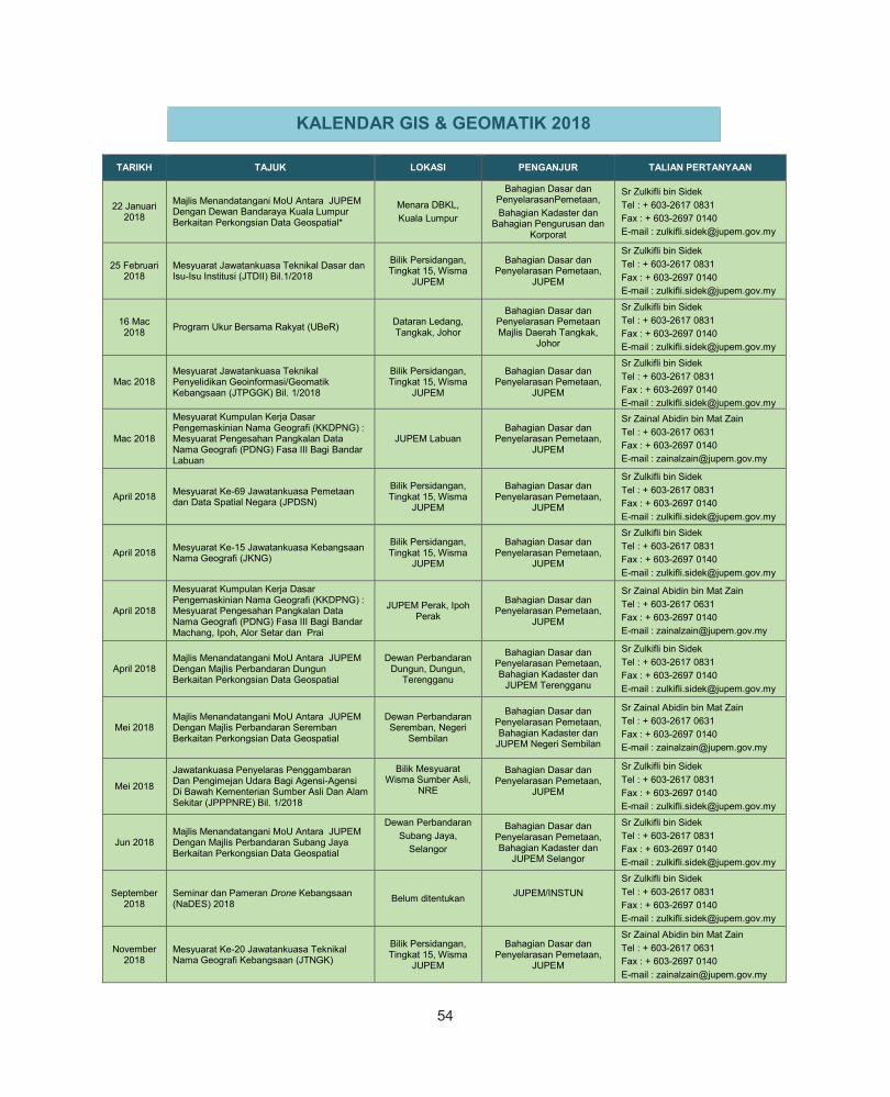
54
TARIKH TAJUK LOKASI PENGANJUR TALIAN PERTANYAAN
22 Januari 2018
Majlis Menandatangani MoU Antara JUPEM Dengan Dewan Bandaraya Kuala Lumpur Berkaitan Perkongsian Data Geospatial*
Menara DBKL, Kuala Lumpur
Bahagian Dasar dan PenyelarasanPemetaan, Bahagian Kadaster dan
Bahagian Pengurusan dan Korporat
Sr Zulkifli bin Sidek Tel : + 603-2617 0831 Fax : + 603-2697 0140 E-mail : [email protected]
25 Februari 2018
Mesyuarat Jawatankuasa Teknikal Dasar dan Isu-Isu Institusi (JTDII) Bil.1/2018
Bilik Persidangan, Tingkat 15, Wisma
JUPEM
Bahagian Dasar dan Penyelarasan Pemetaan,
JUPEM
Sr Zulkifli bin Sidek Tel : + 603-2617 0831 Fax : + 603-2697 0140 E-mail : [email protected]
16 Mac 2018 Program Ukur Bersama Rakyat (UBeR) Dataran Ledang,
Tangkak, Johor
Bahagian Dasar dan Penyelarasan Pemetaan Majlis Daerah Tangkak,
Johor
Sr Zulkifli bin Sidek Tel : + 603-2617 0831 Fax : + 603-2697 0140 E-mail : [email protected]
Mac 2018 Mesyuarat Jawatankuasa Teknikal Penyelidikan Geoinformasi/Geomatik Kebangsaan (JTPGGK) Bil. 1/2018
Bilik Persidangan, Tingkat 15, Wisma
JUPEM
Bahagian Dasar dan Penyelarasan Pemetaan,
JUPEM
Sr Zulkifli bin Sidek Tel : + 603-2617 0831 Fax : + 603-2697 0140 E-mail : [email protected]
Mac 2018
Mesyuarat Kumpulan Kerja Dasar Pengemaskinian Nama Geografi (KKDPNG) : Mesyuarat Pengesahan Pangkalan Data Nama Geografi (PDNG) Fasa III Bagi Bandar Labuan
JUPEM Labuan Bahagian Dasar dan
Penyelarasan Pemetaan, JUPEM
Sr Zainal Abidin bin Mat Zain Tel : + 603-2617 0631 Fax : + 603-2697 0140 E-mail : [email protected]
April 2018 Mesyuarat Ke-69 Jawatankuasa Pemetaan dan Data Spatial Negara (JPDSN)
Bilik Persidangan, Tingkat 15, Wisma
JUPEM
Bahagian Dasar dan Penyelarasan Pemetaan,
JUPEM
Sr Zulkifli bin Sidek Tel : + 603-2617 0831 Fax : + 603-2697 0140 E-mail : [email protected]
April 2018 Mesyuarat Ke-15 Jawatankuasa Kebangsaan Nama Geografi (JKNG)
Bilik Persidangan, Tingkat 15, Wisma
JUPEM
Bahagian Dasar dan Penyelarasan Pemetaan,
JUPEM
Sr Zulkifli bin Sidek Tel : + 603-2617 0831 Fax : + 603-2697 0140 E-mail : [email protected]
April 2018
Mesyuarat Kumpulan Kerja Dasar Pengemaskinian Nama Geografi (KKDPNG) : Mesyuarat Pengesahan Pangkalan Data Nama Geografi (PDNG) Fasa III Bagi Bandar Machang, Ipoh, Alor Setar dan Prai
JUPEM Perak, Ipoh Perak
Bahagian Dasar dan Penyelarasan Pemetaan,
JUPEM
Sr Zainal Abidin bin Mat Zain Tel : + 603-2617 0631 Fax : + 603-2697 0140 E-mail : [email protected]
April 2018 Majlis Menandatangani MoU Antara JUPEM Dengan Majlis Perbandaran Dungun Berkaitan Perkongsian Data Geospatial
Dewan Perbandaran Dungun, Dungun,
Terengganu
Bahagian Dasar dan Penyelarasan Pemetaan, Bahagian Kadaster dan
JUPEM Terengganu
Sr Zulkifli bin Sidek Tel : + 603-2617 0831 Fax : + 603-2697 0140 E-mail : [email protected]
Mei 2018 Majlis Menandatangani MoU Antara JUPEM Dengan Majlis Perbandaran Seremban Berkaitan Perkongsian Data Geospatial
Dewan Perbandaran Seremban, Negeri
Sembilan
Bahagian Dasar dan Penyelarasan Pemetaan, Bahagian Kadaster dan
JUPEM Negeri Sembilan
Sr Zainal Abidin bin Mat Zain Tel : + 603-2617 0631 Fax : + 603-2697 0140 E-mail : [email protected]
Mei 2018
Jawatankuasa Penyelaras Penggambaran Dan Pengimejan Udara Bagi Agensi-Agensi Di Bawah Kementerian Sumber Asli Dan Alam Sekitar (JPPPNRE) Bil. 1/2018
Bilik Mesyuarat Wisma Sumber Asli,
NRE
Bahagian Dasar dan Penyelarasan Pemetaan,
JUPEM
Sr Zulkifli bin Sidek Tel : + 603-2617 0831 Fax : + 603-2697 0140 E-mail : [email protected]
Jun 2018 Majlis Menandatangani MoU Antara JUPEM Dengan Majlis Perbandaran Subang Jaya Berkaitan Perkongsian Data Geospatial
Dewan Perbandaran Subang Jaya,
Selangor
Bahagian Dasar dan Penyelarasan Pemetaan, Bahagian Kadaster dan
JUPEM Selangor
Sr Zulkifli bin Sidek Tel : + 603-2617 0831 Fax : + 603-2697 0140 E-mail : [email protected]
September 2018
Seminar dan Pameran Drone Kebangsaan (NaDES) 2018 Belum ditentukan JUPEM/INSTUN
Sr Zulkifli bin Sidek Tel : + 603-2617 0831 Fax : + 603-2697 0140 E-mail : [email protected]
November 2018
Mesyuarat Ke-20 Jawatankuasa Teknikal Nama Geografi Kebangsaan (JTNGK)
Bilik Persidangan, Tingkat 15, Wisma
JUPEM
Bahagian Dasar dan Penyelarasan Pemetaan,
JUPEM
Sr Zainal Abidin bin Mat Zain Tel : + 603-2617 0631 Fax : + 603-2697 0140 E-mail : [email protected]
60
KALENDAR GIS & GEOMATIK 2018
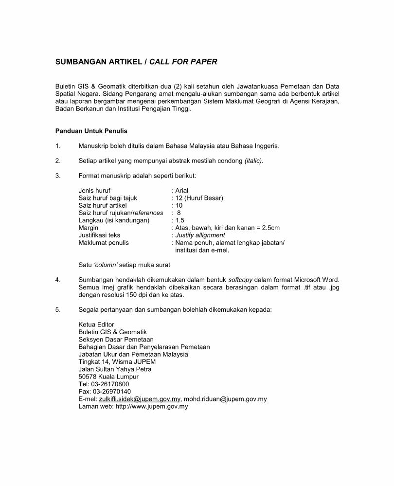
5562
SUMBANGAN ARTIKEL / CALL FOR PAPER Buletin GIS & Geomatik diterbitkan dua (2) kali setahun oleh Jawatankuasa Pemetaan dan Data Spatial Negara. Sidang Pengarang amat mengalu-alukan sumbangan sama ada berbentuk artikel atau laporan bergambar mengenai perkembangan Sistem Maklumat Geografi di Agensi Kerajaan, Badan Berkanun dan Institusi Pengajian Tinggi. Panduan Untuk Penulis 1. Manuskrip boleh ditulis dalam Bahasa Malaysia atau Bahasa Inggeris. 2. Setiap artikel yang mempunyai abstrak mestilah condong (italic). 3. Format manuskrip adalah seperti berikut: Jenis huruf : Arial Saiz huruf bagi tajuk : 12 (Huruf Besar) Saiz huruf artikel : 10 Saiz huruf rujukan/references : 8 Langkau (isi kandungan) : 1.5 Margin : Atas, bawah, kiri dan kanan = 2.5cm Justifikasi teks : Justify allignment Maklumat penulis : Nama penuh, alamat lengkap jabatan/ institusi dan e-mel. Satu ‘column’ setiap muka surat 4. Sumbangan hendaklah dikemukakan dalam bentuk softcopy dalam format Microsoft Word. Semua imej grafik hendaklah dibekalkan secara berasingan dalam format .tif atau .jpg dengan resolusi 150 dpi dan ke atas. 5. Segala pertanyaan dan sumbangan bolehlah dikemukakan kepada: Ketua Editor Buletin GIS & Geomatik Seksyen Dasar Pemetaan
Bahagian Dasar dan Penyelarasan Pemetaan Jabatan Ukur dan Pemetaan Malaysia Tingkat 14, Wisma JUPEM Jalan Sultan Yahya Petra 50578 Kuala Lumpur Tel: 03-26170800 Fax: 03-26970140 E-mel: [email protected], [email protected]
Laman web: http://www.jupem.gov.my

56


![· ketepatan bandingan clan peratus ketepatan. [6 marks] [6 markah] Differentiate accuracy and precision with the help of suitable diagram. Bezakan antara ketepatan dan kepersisan](https://static.fdokumen.site/doc/165x107/5e2c7454da24b752c83381e6/ketepatan-bandingan-clan-peratus-ketepatan-6-marks-6-markah-differentiate-accuracy.jpg)