CONTROL OF A ROBOT ARM USING ITERATIVE LEARNING …eprints.utm.my/id/eprint/1320/1/JT37A5.pdf ·...
17
Jurnal Teknologi, 37(A) Dis. 2002: 55–72 © Universiti Teknologi Malaysia CONTROL OF A ROBOT ARM USING ITERATIVE LEARNING ALGORITHM WITH A STOPPING CRITERION MUSA MAILAH 1 & JONATHAN CHONG WUN SHIUNG Abstract. The robust performance of a robot control scheme is vital to ensure that the robot accomplishes its tasks desirably in a constraint environment involving disturbances, parametric changes, uncertainties and varied operating conditions. The study introduces the Active Force Control and Iterative Learning Algorithm (AFCAIL) scheme with an improved feature in the form of a suitably designed stopping criterion incorporated in the control strategy. The scheme is applied to the control of a horiziontally operated robotic two-link planar manipulator. The proposed stopping criterion is specifically designed to halt the iterative learning process when the conditions related to the accuracy of the performed tasks and the acquisition of appropriate estimated inertia matrix of the robot arm are favourably met. In this way, the robot is said to perform desirably and excellently. The effectiveness of the scheme is also investigated by considering a number different loading and operating conditions. Key words: Robot, active force control, iterative learning algorithm, stopping criterion Abstrak. Prestasi lasak bagi skema kawalan robot sangat perlu untuk memastikan robot dapat bekerja dengan berkesan seperti yang dikehendaki dalam persekitaran terbatas melibatkan gangguan, perubahan parameter, ketidaktentuan dan kepelbagaian keadaan operasi. Kajian yang dibuat adalah berkaitan dengan satu skema kawalan daya aktif dan algoritma pembelajaran berlelaran (AFCAIL) yang melibatkan satu ciri pembaikan dalam bentuk penggunaan kriteria memberhenti yang sesuai dimuatkan dalam strategi kawalan. Skema tersebut digunapakai terhadap sistem pengolah robotik planar berlengan-dua yang beroperasi secara mendatar. Kriteria memberhenti yang dicadangkan adalah direka bentuk untuk memberhentikan proses pembelajaran berlelaran apabila syarat atau keadaan berkaitan dengan kejituan ketika melakukan tugas serta perolehan matriks inersia anggaran pengolah yang dikehendaki dapat dipenuhi. Dengan cara demikian, robot dikatakan dapat beroperasi dengan baik sebagaimana yang diarahkan. Keberkesanan skema juga dikaji dengan mengambil kira beberapa keadaan bebanan dan operasi. Kata kunci: Robot, kawalan daya aktif, algoritma pembelajaran berlelaran, kriterion memberhenti 1.0 INTRODUCTION With the ever increasing in complexity of the robot tasks, a robot control system engineer has to design and come up with a control scheme that will enable the proposed robotic system to perform the required tasks with a high degree of precision, accuracy and reliability particularly under various conditions involving the robot’s interaction 1 Department of Applied Mechanics, Faculty of Mechanical Engineering, Universiti Teknologi Malaysia, 81310 Skudai. [email protected] jt37A[5].pmd 02/16/2007, 19:28 55
-
Upload
nguyendung -
Category
Documents
-
view
219 -
download
0
Transcript of CONTROL OF A ROBOT ARM USING ITERATIVE LEARNING …eprints.utm.my/id/eprint/1320/1/JT37A5.pdf ·...
CONTROL OF A ROBOT ARM USING ITERATIVE LEARNING ALGORITHM 55
Jurnal Teknologi, 37(A) Dis. 2002: 55–72© Universiti Teknologi Malaysia
CONTROL OF A ROBOT ARM USING ITERATIVE LEARNINGALGORITHM WITH A STOPPING CRITERION
MUSA MAILAH1 & JONATHAN CHONG WUN SHIUNG
Abstract. The robust performance of a robot control scheme is vital to ensure that the robotaccomplishes its tasks desirably in a constraint environment involving disturbances, parametric changes,uncertainties and varied operating conditions. The study introduces the Active Force Control andIterative Learning Algorithm (AFCAIL) scheme with an improved feature in the form of a suitablydesigned stopping criterion incorporated in the control strategy. The scheme is applied to the controlof a horiziontally operated robotic two-link planar manipulator. The proposed stopping criterion isspecifically designed to halt the iterative learning process when the conditions related to the accuracyof the performed tasks and the acquisition of appropriate estimated inertia matrix of the robot arm arefavourably met. In this way, the robot is said to perform desirably and excellently. The effectiveness ofthe scheme is also investigated by considering a number different loading and operating conditions.
Key words: Robot, active force control, iterative learning algorithm, stopping criterion
Abstrak. Prestasi lasak bagi skema kawalan robot sangat perlu untuk memastikan robot dapatbekerja dengan berkesan seperti yang dikehendaki dalam persekitaran terbatas melibatkan gangguan,perubahan parameter, ketidaktentuan dan kepelbagaian keadaan operasi. Kajian yang dibuat adalahberkaitan dengan satu skema kawalan daya aktif dan algoritma pembelajaran berlelaran (AFCAIL)yang melibatkan satu ciri pembaikan dalam bentuk penggunaan kriteria memberhenti yang sesuaidimuatkan dalam strategi kawalan. Skema tersebut digunapakai terhadap sistem pengolah robotikplanar berlengan-dua yang beroperasi secara mendatar. Kriteria memberhenti yang dicadangkanadalah direka bentuk untuk memberhentikan proses pembelajaran berlelaran apabila syarat ataukeadaan berkaitan dengan kejituan ketika melakukan tugas serta perolehan matriks inersia anggaranpengolah yang dikehendaki dapat dipenuhi. Dengan cara demikian, robot dikatakan dapat beroperasidengan baik sebagaimana yang diarahkan. Keberkesanan skema juga dikaji dengan mengambil kirabeberapa keadaan bebanan dan operasi.
Kata kunci: Robot, kawalan daya aktif, algoritma pembelajaran berlelaran, kriterion memberhenti
1.0 INTRODUCTION
With the ever increasing in complexity of the robot tasks, a robot control systemengineer has to design and come up with a control scheme that will enable the proposedrobotic system to perform the required tasks with a high degree of precision, accuracyand reliability particularly under various conditions involving the robot’s interaction
1 Department of Applied Mechanics, Faculty of Mechanical Engineering, Universiti Teknologi Malaysia,81310 Skudai. [email protected]
jt37A[5].pmd 02/16/2007, 19:2855
MUSA MAILAH & JONATHAN CHONG WUN SHIUNG56
with its environment. This also implies that the system has to be robust, stable andeffectively capable to accomplish the prescribed tasks even in the presence ofdisturbances, parametric changes, uncertainties and varied operating conditions. Therehas been a growing trend in the development and implementation of intelligentmechanisms in robot control [1,2]. These mechanisms include the application of neuralnetworks [3,4], fuzzy logics [5,6] and iterative learning algorithms [7–12]. They arenormally incorporated into the robot force control strategy to enhance the system’soverall performance by generally introducing an automatic decision making facility inthe control loop. One such control scheme is the active force control (AFC) strategy[13] applied to the control of a robot arm. This control scheme together with the suitablyproposed intelligent mechanism is the main focus of the study. AFC has been shownto be very robust and effective in countering disturbances and varied operatingconditions. A number of intelligent AFC schemes has been developed using neuralnetwork, fuzzy logics and iterative learning algorithms [14,15]. It is the aim of the paperto improvise the latter scheme known as Active Force Control And Iterative Learning(AFCAIL) to include a stopping criterion that is necesssary to halt the operation of therobot arm, upon satisfying a number of prescribed conditions.
The paper is structured as follows; the first part describes the motivation of thestudy and the basic underlying principles of the AFC and iterative learning theories. Itis followed by a narration of the design of the stopping criterion and later, the simulationstudy to verify the effectiveness of the proposed concept. The analysis of the resultsensues and finally a conclusion is drawn plus a numbers of suggestions for futureworks outlined.
2.0 PROBLEM STATEMENT
The main drawback of the AFC scheme is the task of computing the estimated inertiamatrix of the robot arm which is essential in the AFC feed-forward control loop. Theapplication of the iterative learning has been proven to be very effective in estimatingthe appropriate inertia matrix of the robot arm automatically, continuously and on-linewhile the robot is performing its task [14]. However, the computation of the matrix isdone in a ‘free flowing’ manner without any reference made to corrective actions to betaken to inform the system that the learning process has been complete. In other words,there is no stopping mechanism to halt the iteration process even though the matrixhas been considered appropriately estimated and the system has been performingdesirably. There is a danger of the system going into instability as iteration continuesinfinitely. Thus, a suitable stopping criterion for the AFCAIL scheme should bedesigned and developed based on a set of pre-defined conditions such as those relatedto accuracy and stability. The incorporation of the stopping criterion is expected toprovide a clearer picture of the system pertaining to its performance and could alsominimise the time and resources involved.
jt37A[5].pmd 02/16/2007, 19:2856
CONTROL OF A ROBOT ARM USING ITERATIVE LEARNING ALGORITHM 57
3.0 ACTIVE FORCE CONTROL
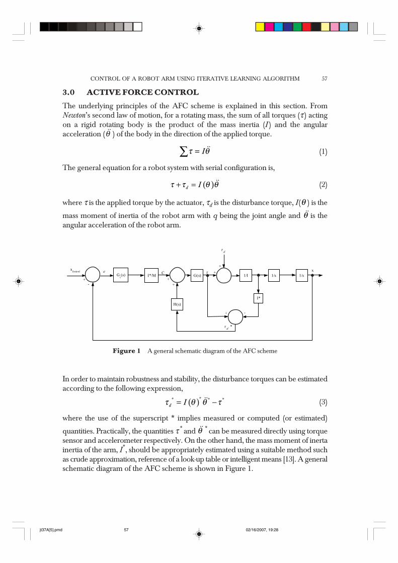
The underlying principles of the AFC scheme is explained in this section. FromNewton’s second law of motion, for a rotating mass, the sum of all torques (τ ) actingon a rigid rotating body is the product of the mass inertia (I ) and the angularacceleration (θ ) of the body in the direction of the applied torque.
τ θ=∑ I (1)
The general equation for a robot system with serial configuration is,
( )τ τ θ θ+ =d I (2)
where τ is the applied torque by the actuator, τd is the disturbance torque, I(θ ) is the
mass moment of inertia of the robot arm with q being the joint angle and θ is theangular acceleration of the robot arm.
Figure 1 A general schematic diagram of the AFC scheme
I*/M
H(s)
G(s) 1/I 1/s 1/s+
-
++
I*
+ -
++
Gc(s)
*dτ
dτ
xxdesired e C τ
In order to maintain robustness and stability, the disturbance torques can be estimatedaccording to the following expression,
( )τ θ θ τ= −** * *d I (3)
where the use of the superscript * implies measured or computed (or estimated)
quantities. Practically, the quantities τ * and θ * can be measured directly using torquesensor and accelerometer respectively. On the other hand, the mass moment of inertainertia of the arm, I*, should be appropriately estimated using a suitable method suchas crude approximation, reference of a look-up table or intelligent means [13]. A generalschematic diagram of the AFC scheme is shown in Figure 1.
jt37A[5].pmd 02/16/2007, 19:2857
MUSA MAILAH & JONATHAN CHONG WUN SHIUNG58
As mentioned before, in the AFC scheme applied to a robot system, the maincomputational burden is the multiplication of the estimated inertia matrix with theangular acceleration of the arm before fed into the AFC feed-forward loop. A suitablecontroller Gc(s) has to be determined and the following expression is considered:
G(s)W(s) = 1 (4)
where G(s) = Kt and W(s) = 1/Kt with Kt being the motor torque constant.Like many other control schemes, the AFC scheme also incorporates classical control
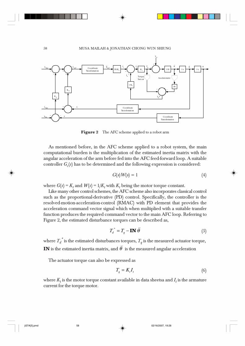
such as the proportional-derivative (PD) control. Specifically, the controller is theresolved-motion-acceleration-control (RMAC) with PD element that provides theacceleration command vector signal which when multiplied with a suitable transferfunction produces the required command vector to the main AFC loop. Referring toFigure 2, the estimated disturbance torques can be described as,
θ= −*d qT T IN (5)
where Td* is the estimated disturbances torques, Tq is the measured actuator torque,
IN is the estimated inertia matrix, and θ is the measured angular acceleration
The actuator torque can also be expressed as
=q t tT K I (6)
where Kt is the motor torque constant available in data sheetsa and It is the armaturecurrent for the torque motor.
Figure 2 The AFC scheme applied to a robot arm
CoordinateTra nsformati on
IN/K t
K p
K d
1/Kt
K t 1/H 1/s 1/s
CoordinateTransformation
CoordinateTra nsformat ion
++
++
refx refθ Ic It Tq +
+
TorqueSen sor Accelerometer
IN+ -
T d
θ θ θ
+ -xbar x
barx x-+
barx
Td*
++Ia
jt37A[5].pmd 02/16/2007, 19:2858
CONTROL OF A ROBOT ARM USING ITERATIVE LEARNING ALGORITHM 59
Thus, Eq. (5) becomes
θ= −*d t tT K I IN (7)
Note that the torque current (of the motor), It = Ic + Ia where Ic is the current commandvector and Ia the compensated current vector.
4.0 ITERATIVE LEARNING ALGORITHM WITH AFC
Iterative learning control is an approach to improving the transient response performanceof systems that operate repetitively over a fixed time interval [7–12]. It is also known as“betterment process” or “repetitive control”. In other words, the iterative learningalgorithm will cause the performance of a dynamical system (based on some errorcriterion) to become better as time increases. Symbolically, the track error, TEapproaches the zero datum as time heads for infinity, i.e., TE→0 as t→∞. Arimotoet al. [9] has provided a sufficiently in-depth analysis of the convergence, stability androbustness of the iterative learning algorithm incidentally employed in the study.
For the AFC scheme, the iterative learning algorithm is used to estimate the inertiamatrix based on the trajectory track error of the arm when describing a referencetrajectory. The track error [14] may be defined as,
( ) ( )= − + −k bar barTE x x y y22 (8)
where xbar and ybar are the desired Cartesian coordinates of the end-effector and x andy are the actual Cartesian coordinates of the end-effector.
Equation (8) is also known as the root of sum-squared track error. It differs slightlyfrom the one used by Arimoto et al. (absolute track error was used instead) [7–9]. Thepurpose of using the sum-squared terms in the equation is to ensure that only positivevalues for the TEk were generated since it has been theoretically asserted that thevalues of the inertia matrix of the arm should be always positive definite [16]. For theproposed scheme, the following equation was used,
( )φ Γ+ = + +k k kd / dt TE1IN IN (9)
where +k 1IN is the next step value of the estimated inertia matrix
kIN is the current estimated inertia matrixTEk is the current root of sum-squared track errorφ and Γ are suitable positive definite constants or learning parameters
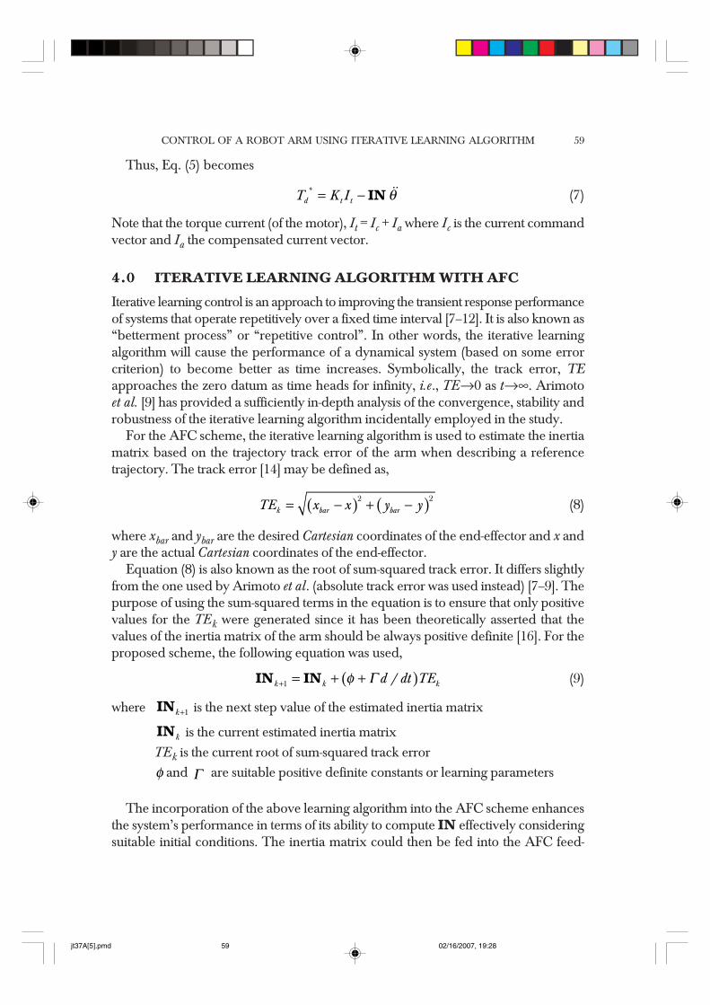
The incorporation of the above learning algorithm into the AFC scheme enhancesthe system’s performance in terms of its ability to compute IN effectively consideringsuitable initial conditions. The inertia matrix could then be fed into the AFC feed-
jt37A[5].pmd 02/16/2007, 19:2859
MUSA MAILAH & JONATHAN CHONG WUN SHIUNG60
Figure 3 The AFC and iterative learning control scheme
forward loop to effect the control action. Figure 3 illustrates how the AFCAIL schemeworks. Information about the robot’s trajectory or motion while performing a specifictask is relayed to a feedback sub-system in the outer control loop of the overall controlscheme when the robot moves. This information is compared with the desired referencetrajectory and the difference between the two gives the track error. The resulting trackerror is then used by the iterative learning algorithm to determine the inertia matrix ofthe arm for the next cycle (the next time instant data is taken or the next samplingtime).
Start
Initialization anddeclaration of variables
Robot describes areference trajectory
Iterative Learning AlgorithmINININININkkkkk+1+1+1+1+1 = INININININkkkkk + (φ + Γd /dt )TEk
Robot Dynamic Model
Stoppingcriterionfulfilled?
Computed INININININ
Stop
No
Yes
TEk
INININININ kkkkk +1+1+1+1+1
I NI NI NI NI N kkkkk
TEk+1
jt37A[5].pmd 02/16/2007, 19:2860
CONTROL OF A ROBOT ARM USING ITERATIVE LEARNING ALGORITHM 61
θ
Consequently, this estimated inertia matrix is introduced into the main AFC loopwhere the compensation of the disturbances by way of estimating the disturbancetorques takes place. The robot is thus ‘prepared’ to counter the effects that cause theprevious error and ultimately force the system to behave robustly. The track error wasgradually reduced to minimal value as iteration proceeded and hence producing agood appropriate value of the inertia matrix in the process.
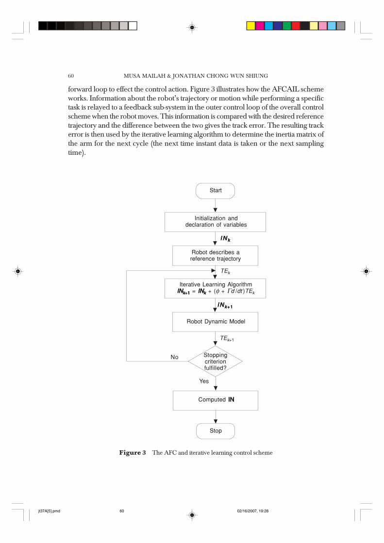
A schematic block diagram representing the AFCAIL scheme is shown in Figure4. Note that the dashed box contains the iterative learning mechanism to compute therequired estimated inertia matrix based on the trajectory track error. A PD controlwith suitable controller gains (Kp and Kd) embeds in the resolved-motion-acceleration-control (RMAC) can be seen in the left hand side of the diagram. By way of applyinga coordinate transformation method, an angular acceleration vector command θrefis produced. This is later multiplied with a suitable transfer function before being fedinto the torque control loop. Disturbances (external), Td, can be introduced to test thesystem’s robustness. A number of disturbances are modelled in the study.
5.0 THE STOPPING CRITERION
An iterative method computes successive approximations to the solution of a systemsuch that the output of the system approaches an appropriate value as the time increases.The learning process, as it is oftenly referred to, however, is accomplished infinitelywith the possibility of over learning, a term to describe a condition or an instant whenthe system is said to have performed excellently but the system keeps on executingthe learning algorithm iteratively but irrelevantly due to the absence of a stoppingmechanism. This condition could lead to instability of the system once it enters a
Figure 4 The AFCAIL scheme
IN/Kt Kt
1/Kt
1 / H 1/s 1/s
INk
Θ ref
++
Ic Tq
Td
Td* -+
++coordinate
transformation
Kd
Kp
coordinate transformati on
coordinate transfo rma tion
ΘΘΘIt
Ia
x refxbar
xbar
xbar
+
+
-
-
++
++
x
x
++Γ(t)d/dt
Φ (t)+
TEk
INk+1
.
.. .. .. ..
.
.
jt37A[5].pmd 02/16/2007, 19:2861
MUSA MAILAH & JONATHAN CHONG WUN SHIUNG62
‘dangerous zone’ where the estimated parameter of the system could no longermaintains a suitable range of values that ultimately triggers a severe degradation of thesystem’s performance [14]. Thus, a mechanism must be incorporated into the algorithmso that the system knows how to react positively (i.e., stop the iteration) in the event ofthe afore-mentioned occurrence. This leads to the design of the stopping criterion asproposed in the study. The main purpose of the stopping criterion used in this study isto stop the simulation of the AFCAIL scheme (for a two-link planar manipulator)automatically if a set of pre-defined stability and accuracy conditions are fulfilled.
The estimated inertia matrix can then be obtained when the system is deemed tobe performing excellently and with a high degree of stability and accuracy. Generally,the design of stopping criterion has to take into account one or more of the five aspectsbelow [17]:
(i) The convergence test
A convergence test is the gradual decreasing of error until it reaches a certainminimal value or zero depending on the accuracy requirements of the test. Whenthe error reaches an acceptable range, the iterations are stopped.
(ii) The iterations count limit
It is common practice to limit the number of iterations to prevent situations wherethe iterative system exhibits no progress towards the solution or progress that isunacceptably slow. This would be a waste of time and seemingly an unsystematicand impractical approach.
(iii) Resources to perform/continue the algorithm
Insufficient-resource errors occur when the iterative solver does not have enoughworkspace to perform its operations. Therefore the size of the workspace has tobe checked before beginning the iterations. However, with the highly advancedcomputers of today, this problem can easily be tackled.
(iv) Breaking down of the algorithm
This is the mathematical condition when the iterative algorithm involves divisionby zeros that is undefined.
(v) External error
External errors are errors that are ‘outside’ the iterative system. Being a subsystem,the iterative learning interacts with other subsystems from which it receives andsends out signals to. Errors in these signals can cause a breakdown in the learningalgorithm.
jt37A[5].pmd 02/16/2007, 19:2862
CONTROL OF A ROBOT ARM USING ITERATIVE LEARNING ALGORITHM 63
Based on the past simulation results of the AFCAIL scheme for a two-link horizontalplanar manipulator, a design of the stopping criterion that is based on the convergencetest is chosen as the most appropriate. This is because the iterative learning algorithmcomputes the estimated inertia matrix, which is a function of the trajectory error that isobserved to be gradually decreasing with time. Thus, the logical choice would be tobase the design of the stopping criterion on the sum-squared track error from Eq. (8).The following criteria have been proposed for the AFCAIL scheme:
(i) Criterion 1 – Trajectory error
The trajectory error magnitude converges towards zero and goes below amagnitude of n m determined by the requirements of the system.
(ii) Criterion 2 – Length of time, t
The trajectory error remains continuously within this range 0 ≤ TEk ≤ n for aspecified period of time, t that will be based on the time taken for each cycle,tstop. For example, the time required is t = a × tstop where a is the number ofcycles.
The values of n and a are not specified as yet, to create a more general stoppingcriterion that can be implemented into any other AFCAIL scheme. To illustrate theidea of the proposed stopping criterion design, a reference should be made to Figure5 where a flow chart of the system is shown.
5.1 Stopping Criterion Model
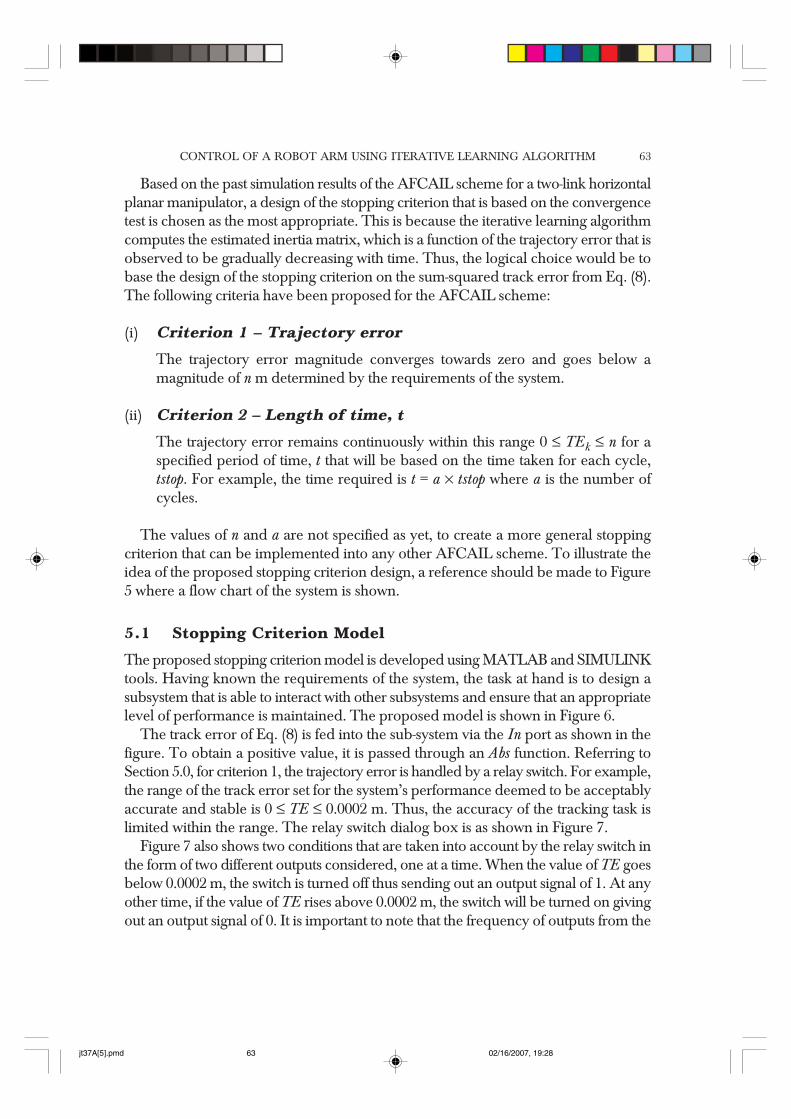
The proposed stopping criterion model is developed using MATLAB and SIMULINKtools. Having known the requirements of the system, the task at hand is to design asubsystem that is able to interact with other subsystems and ensure that an appropriatelevel of performance is maintained. The proposed model is shown in Figure 6.
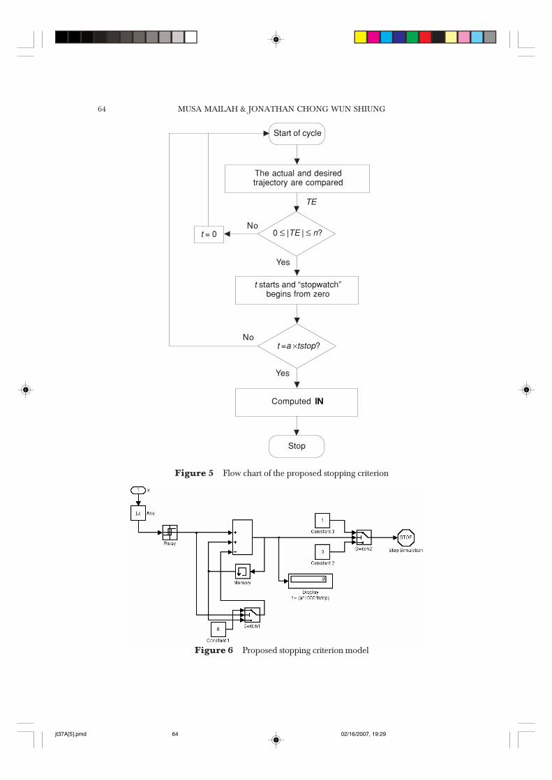
The track error of Eq. (8) is fed into the sub-system via the In port as shown in thefigure. To obtain a positive value, it is passed through an Abs function. Referring toSection 5.0, for criterion 1, the trajectory error is handled by a relay switch. For example,the range of the track error set for the system’s performance deemed to be acceptablyaccurate and stable is 0 ≤ TE ≤ 0.0002 m. Thus, the accuracy of the tracking task islimited within the range. The relay switch dialog box is as shown in Figure 7.
Figure 7 also shows two conditions that are taken into account by the relay switch inthe form of two different outputs considered, one at a time. When the value of TE goesbelow 0.0002 m, the switch is turned off thus sending out an output signal of 1. At anyother time, if the value of TE rises above 0.0002 m, the switch will be turned on givingout an output signal of 0. It is important to note that the frequency of outputs from the
jt37A[5].pmd 02/16/2007, 19:2863
MUSA MAILAH & JONATHAN CHONG WUN SHIUNG64
Figure 5 Flow chart of the proposed stopping criterion
Start of cycle
The actual and desiredtrajectory are compared
t starts and “stopwatch”begins from zero
t =a ×tstop?
Computed INININININ
Stop
No
Yes
TE
0 ≤ |TE | ≤ n?
Yes
Not = 0
Figure 6 Proposed stopping criterion model
jt37A[5].pmd 02/16/2007, 19:2964
CONTROL OF A ROBOT ARM USING ITERATIVE LEARNING ALGORITHM 65
relay switch depends on the sampling time of the track error system, e.g., if the samplingtime is 0.001 s (track error values are updated for every 0.001 s), the relay switch will besending outputs for every 0.001 s.
5.2 Stopwatch Mechanism
The output signals from the relay switch will then be passed on to a summing junctionand also to Switch 1 (Figure 6). When the input to the junction equals to 1 (which isdesirable), two things will happen:
(i) The value 1 will be added to the previous sum stored in the memory block (forthe first time, the sum in the memory block is equal to 0).
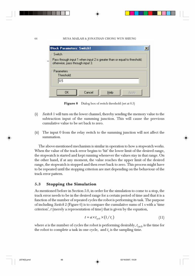
(ii) Switch 1 will pass on the constant 0 to be added at the summing junction andtherefore there will be no effect on the summing operation at this point in time. Athreshold value of the switch is set to 0.5, which means if the input is greater orequal to 0.5, the upper channel of the switch will be switched on and the lowerchannel off and vice versa. The dialog box of the switch is shown in Figure 8.
The adding of 1 s will continue throughout the simulation until the track error goesabove the desired range, thus giving the output 0 from the relay switch. When thishappens,
Figure 7 Relay switch dialog box
jt37A[5].pmd 02/16/2007, 19:2965
MUSA MAILAH & JONATHAN CHONG WUN SHIUNG66
(i) Switch 1 will turn on the lower channel, thereby sending the memory value to thesubtraction input of the summing junction. This will cause the previouscumulative value to be set back to zero.
(ii) The input 0 from the relay switch to the summing junction will not affect thesummation.
The above-mentioned mechanism is similar in operation to how a stopwatch works.When the value of the track error begins to ‘hit’ the lower limit of the desired range,the stopwatch is started and kept running whenever the values stay in that range. Onthe other hand, if at any moment, the value reaches the upper limit of the desiredrange, the stopwatch is stopped and then reset back to zero. This process might haveto be repeated until the stopping criterion are met depending on the behaviour of thetrack error pattern.
5.3 Stopping the Simulation
As mentioned before in Section 5.0, in order for the simulation to come to a stop, thetrack error needs to be in the desired range for a certain period of time and that it is afunction of the number of repeated cycles the robot is performing its task. The purposeof including Switch 2 (Figure 6) is to compare the cumulative sums of 1 s with a ‘timecriterion’, t (merely a representation of time) that is given by the equation,
( )= × ×cycle st a t / t1 (11)
where a is the number of cycles the robot is performing desirably, tcycle is the time forthe robot to complete a task in one cycle, and ts is the sampling time.
Figure 8 Dialog box of switch threshold (set at 0.5)
jt37A[5].pmd 02/16/2007, 19:2966
CONTROL OF A ROBOT ARM USING ITERATIVE LEARNING ALGORITHM 67
The value of a has to be at least 2 (indicating two cycles) in order to enable a clearerobservation of the INININININ values and the track errors computed by the system. When thesum of 1 s equals t, Switch 2 (that has a threshold value as described by Equation (11)),will switch on the upper channel of the switch allowing the constant 1 to pass through.If the sum of 1 s is below t, the constant 0 will be passed through instead.
The final block is the STOP block that stops the simulation when its input is non-zero. Thus when the criterion, sum of 1 s equals t, the simulation will be stoppedautomatically.
6.0 SIMULATION RESULTS
Simulation was performed on the AFCAIL scheme to investigate the effectiveness ofthe stopping criterion model. Two loading conditions were considered; one withoutdisturbances while the other with a set of introduced disturbances.
The parameters of the simulation used in the study were:
Magnitude of the desired track error goal, TE ≤ 0.0002 mNumber of desirable cycles, a = 3 (value must be at least 2)Time for one cycle, tcycle = 3.142 sMaximum total simulation time = 25 sSampling time, ts = 0.001 s
Initial conditions (for the iterative learning algorithm):IN11 = 0.004 kgm2 and IN22 = 0.002 kgm2
Applied simultaneous disturbances to the robot arm:Harmonic force, Fh = h sin t where the amplitude, h = 40 NSpring force, Fs = kx where the spring constant, k = 150 N/m
The results of the simulation can be seen in Figures 9 and 10. A summary of theresults is shown in Table 1.
7.0 ANALYSIS AND DISCUSSION
From graphs of Figure 9, it is observed that the system does not meet the accuracyrequirements determined in the simulation parameters. Thus, the simulation wereexecuted for the full 25 s (or approximately 8 cycles) without stopping, based on thecriterion set. This provides a clearer picture for the designer of the control system whohas to make necessary alterations to the system if the control scheme is required toperform excellently in the presence of the introduced disturbances. On the other hand,the graphs of Figure 10 show that that the system without disturbances readily meetsthe set accuracy criterion. The magnitude of the trajectory error remains below 0.0002
jt37A[5].pmd 02/16/2007, 19:2967
MUSA MAILAH & JONATHAN CHONG WUN SHIUNG68
(c)
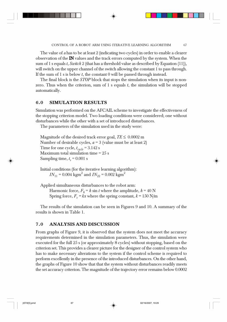
Figure 9 Simulation results with the applied disturbances
(a) (b)
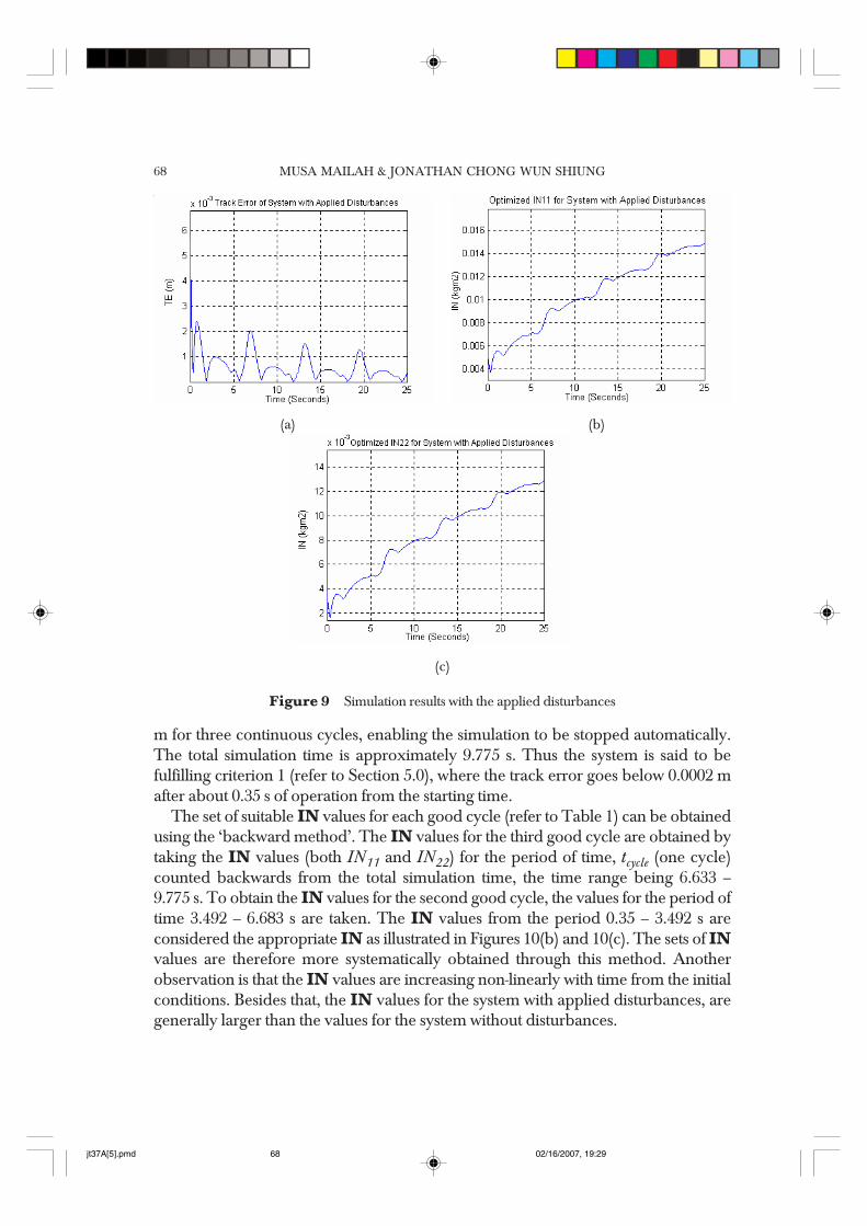
m for three continuous cycles, enabling the simulation to be stopped automatically.The total simulation time is approximately 9.775 s. Thus the system is said to befulfilling criterion 1 (refer to Section 5.0), where the track error goes below 0.0002 mafter about 0.35 s of operation from the starting time.
The set of suitable IN values for each good cycle (refer to Table 1) can be obtainedusing the ‘backward method’. The IN values for the third good cycle are obtained bytaking the IN values (both IN11 and IN22) for the period of time, tcycle (one cycle)counted backwards from the total simulation time, the time range being 6.633 –9.775 s. To obtain the IN values for the second good cycle, the values for the period oftime 3.492 – 6.683 s are taken. The IN values from the period 0.35 – 3.492 s areconsidered the appropriate IN as illustrated in Figures 10(b) and 10(c). The sets of INvalues are therefore more systematically obtained through this method. Anotherobservation is that the IN values are increasing non-linearly with time from the initialconditions. Besides that, the IN values for the system with applied disturbances, aregenerally larger than the values for the system without disturbances.
jt37A[5].pmd 02/16/2007, 19:2968
CONTROL OF A ROBOT ARM USING ITERATIVE LEARNING ALGORITHM 69
(c)
Figure 10 Simulation results without disturbances
(a) (b)
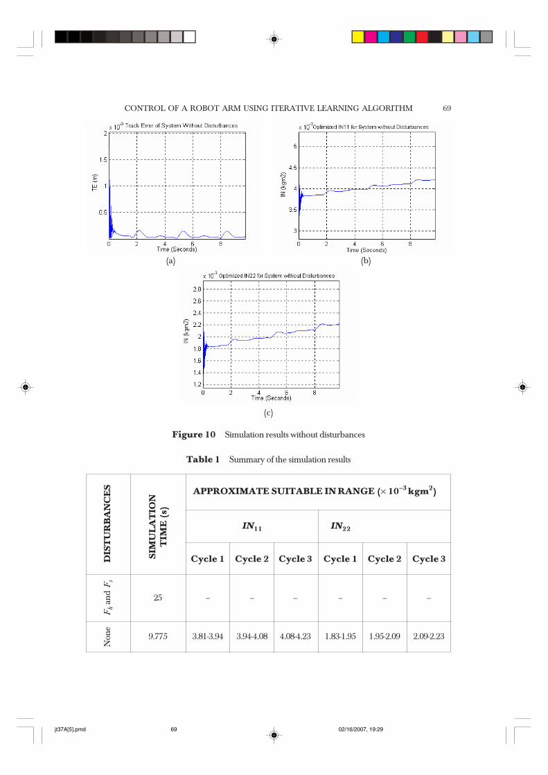
Table 1 Summary of the simulation results
IN11 IN22
Cycle 1 Cycle 2 Cycle 3 Cycle 1 Cycle 2 Cycle 3
25 – – – – – –
9.775 3.81-3.94 3.94-4.08 4.08-4.23 1.83-1.95 1.95-2.09 2.09-2.23
DIS
TU
RB
AN
CE
S
SIM
UL
AT
ION
TIM
E (
s)
Non
eF
h an
d F
s
APPROXIMATE SUITABLE IN RANGE (× 10–3 kgm2)
jt37A[5].pmd 02/16/2007, 19:2969
MUSA MAILAH & JONATHAN CHONG WUN SHIUNG70
8.0 CONCLUSIONS
The stopping criterion proposed in the study was indeed effective in stopping thesimulation of the AFCAIL scheme automatically when conditions related to theaccuracy and stability of the system are met. There are two main criteria that need tobe determined, namely, the suitable range of the desired track error and the length oftime when the error is said to remain within the acceptable range. The proposedstopping criterion model has been shown to provide a systematic method in obtainingsuitable values of IN. In addition to that, it can also be used as a tool to study theeffects of changes made to the control scheme related to the parameters, robotic tasks,operating and loading conditions particularly when the simulation results are not easilypredictable. These could be a subject of future works that could be carried out.
ACKNOWLEDGEMENTS
The authors would like to thank the Ministry of Science and Technology and theUniversiti Teknologi Malaysia for providing the financial support and facilities. Thisresearch was supported using an IRPA grant of Vot. No. 72361.
REFERENCES[1] Astrom, K. J., and T. J. McAvoy. 1992. Intelligent Control: An Overview and Evaluation. In David A.
White, Donald A. Sofge, Eds., Handbook of Intelligent Control : Neural, Fuzzy and Adaptive Approaches, NewYork: Van Nostrand Reinhold, 3-34.
[2] Tzafestas, S. G., 1991. Engineering Systems with Intelligence – Concepts, Tools and Applications, London:Kluwer Academic Publishers.
[3] Saad, M., P. Bigras, L. A. Dessaint, and K. Al-Haddad. 1994. Adaptive Robot Control Using NeuralNetworks. IEEE Transactions on Industrial Electronics. 41(2): 173-181.
[4] Gardner, J. F., A. Brandt, and G. Luecke. 1993. Applications of Neural Networks for CoordinateTransformations in Robotics. Journal of Intelligent and Robotic Systems. 8: 361-373.
[5] Ohnishi, K., M. Shibata, T. Murakami. 1996. A Unified Approach to Position and Force Control by FuzzyLogic. IEEE Transactions on Industrial Electronics. 43(1): 81-7.
[6] Jamshidi, M., N. Vadiee, and T. J. Ross. 1993. Fuzzy Logic and Control. New Jersey: Prentice-Hall International,Inc.
[7] Arimoto, S., S. Kawamura and F. Miyazaki. 1985. Hybrid Position/Force Control of Robot ManipulatorsBased on Learning Method. Proc. of Int’l. Conf. on Advanced Robotics. 235-242.
[8] Arimoto, S., S. Kawamura and F. Miyazaki. 1984. Bettering Operation of Robots by Learning. RoboticSystems. 123-140.
[9] Arimoto, S., S. Kawamura and F. Miyazaki, 1986. Convergence, Stability and Robustness of LearningControl Schemes for Robot Manipulators. In M. Jamshidi, L. Y. S. Luh, and M. Shahinpoor. ed. RecentTrends in Robotics: Modeling, Control and Education. 307-316.
[10] Moore, K. L., 1993. Iterative Learning Control For Deterministic Systems. London: Springer Verlag.[11] Moore, K. L., M. Dahleh, and S.P. Bhattacharyya. 1990. Adaptive Gain Adjustment for a Learning Control
Method for Robotics. Procs. of Int’l Conf. On Robotics and Automation. Ohio, 2095-2099.[12] Bondi, P., G. Casalino, L. Gambardella, 1988. On the Iterative Learning Control Theory for Robotic
Manipulators. IEEE Journal on Robotics and Automation. 4(1): 14-22.[13] Hewit, J. R., and J. S. Burdess. 1981. Fast Dynamic Decoupled Control for Robotics Using Active Force
Control. Mechanism and Machine Theory. 16(5): 535-542.
jt37A[5].pmd 02/16/2007, 19:2970

CONTROL OF A ROBOT ARM USING ITERATIVE LEARNING ALGORITHM 71
[14] Mailah, M. 1998. Intelligent Active Force Control of a Rigid Robot Arm Using Neural Network and IterativeLearning Algorithms. Ph.D. Thesis, University of Dundee.
[15] Mailah, M. and N. I Ab. Rahim. 2000. Intelligent Active Force Control of A Robot Arm Using Fuzzy Logic.Procs. of IEEE Int’l Conf. on Intelligent Systems and Technologies. TENCON 2000, Kuala Lumpur, II: 291-297.
[16] Asada, H., and J. E. Slotine. 1986. Robot Analysis and Control. New York: John Wiley and Sons Inc.[17] John, K. W. 1995. Stopping Criterion, http://www-users.cs.umn.edu/~kewu/iters/node16.html, modified: 2
June 1999.
jt37A[5].pmd 02/16/2007, 19:2971