
Corrosion Studies of Conductive Paint Coating Using Battery ...
12
Int. J. Electrochem. Sci., 7 (2012) 6976 - 6987 International Journal of ELECTROCHEMICAL SCIENCE www.electrochemsci.org Corrosion Studies of Conductive Paint Coating Using Battery Cathode Waste Material in Sodium Chloride Solution Muhammad Firdaus Mohd Nazeri, Mohd Shahadan Mohd Suan, Mohamad Najmi Masri, Nurhaswani Alias, and Ahmad Azmin Mohamad * School of Materials and Mineral Resources Engineering, Universiti Sains Malaysia, 14300, Nibong Tebal, Penang, Malaysia * E-mail: [email protected] Received: 23 June 2012 / Accepted: 15 July 2012 / Published: 1 August 2012 A conductive paint coating was prepared using a mixture of cathode waste materials (CWM) as the filler and epoxy resin as the binder. The optimum electrical conductivity of 5.33 × 10 -4 S cm -1 was obtained at 25 wt% CWM. It was found that the contact of the filler improves the electrical conductivity. However, the corrosion potential (E corr ) values of paint/mild steel decreased with the higher percentage of CWM to the paint. The low percentage incorporation of the filler shows the best ability to protect the mild steel from corrosion among the coatings. Keywords: Cathode waste materials; Conductive paint coating; Corrosion; Epoxy resin. 1. INTRODUCTION Paint coating is regarded as one of the most economical and widely used methods of protecting metal. The coating layer acts as a barrier that isolates the metal from the corrosive environment that causes deterioration of material. Thus, the coating layer enhances the lifetime of the metal [1]. Epoxy resins are one of the most well-known binders that are used for a wide variety of protective coatings because of their excellent adhesion, good mechanical properties, and tremendous corrosion resistance performance [2]. At the same time, pigments are added to give extra characteristics to meet special requirements for various new applications [3, 4]. Conductive paint is a type of paint coating that is produced by adding various types of electrical conducting materials into the binder such as metal [3], carbon black [5, 6], graphite [7, 8], conductive polymers [2, 8-10] and carbon fibres [11, 12]. By being conductive, the paint can be used as an antistatic agent to reduce or eliminate the buildup of static charges. The static charges could
Transcript of Corrosion Studies of Conductive Paint Coating Using Battery ...
Int. J. Electrochem. Sci., 7 (2012) 6976 - 6987
International Journal of
ELECTROCHEMICAL SCIENCE
www.electrochemsci.org
Corrosion Studies of Conductive Paint Coating Using Battery
Cathode Waste Material in Sodium Chloride Solution
Muhammad Firdaus Mohd Nazeri, Mohd Shahadan Mohd Suan, Mohamad Najmi Masri,
Nurhaswani Alias, and Ahmad Azmin Mohamad*
School of Materials and Mineral Resources Engineering, Universiti Sains Malaysia, 14300, Nibong
Tebal, Penang, Malaysia *E-mail: [email protected]
Received: 23 June 2012 / Accepted: 15 July 2012 / Published: 1 August 2012
A conductive paint coating was prepared using a mixture of cathode waste materials (CWM) as the
filler and epoxy resin as the binder. The optimum electrical conductivity of 5.33 × 10⁻⁴
S cm-1
was
obtained at 25 wt% CWM. It was found that the contact of the filler improves the electrical
conductivity. However, the corrosion potential (Ecorr) values of paint/mild steel decreased with the
higher percentage of CWM to the paint. The low percentage incorporation of the filler shows the best
ability to protect the mild steel from corrosion among the coatings.
Keywords: Cathode waste materials; Conductive paint coating; Corrosion; Epoxy resin.
1. INTRODUCTION
Paint coating is regarded as one of the most economical and widely used methods of protecting
metal. The coating layer acts as a barrier that isolates the metal from the corrosive environment that
causes deterioration of material. Thus, the coating layer enhances the lifetime of the metal [1]. Epoxy
resins are one of the most well-known binders that are used for a wide variety of protective coatings
because of their excellent adhesion, good mechanical properties, and tremendous corrosion resistance
performance [2]. At the same time, pigments are added to give extra characteristics to meet special
requirements for various new applications [3, 4].
Conductive paint is a type of paint coating that is produced by adding various types of
electrical conducting materials into the binder such as metal [3], carbon black [5, 6], graphite [7, 8],
conductive polymers [2, 8-10] and carbon fibres [11, 12]. By being conductive, the paint can be used
as an antistatic agent to reduce or eliminate the buildup of static charges. The static charges could
Int. J. Electrochem. Sci., Vol. 7, 2012
6977
cause damage to static-sensitive objects such as electronic devices and might produce sparks that
would ignite flammable gasses or liquid [3, 5, 8, 9]. Various corrosion studies have been performed on
conductive paint coating. Significant corrosion protection was reportedly obtained by Armelin et al. [2]
and Masri et al. [5] for samples coated with conducting polymer in sodium chloride (NaCl) solution.
Freitas et al. [13] found that the growing disposal of spent zinc-carbon batteries has created a
serious environmental problem. This kind of battery consists of various materials that decompose and
deteriorate with difficulty, and thus finally leach out and contribute to landfill. Nevertheless, zinc-
carbon batteries can be recycled since one of the materials, the cathode waste material (CWM), can be
used as a conductive filler in paint coating due to the conductive behaviour of the carbon (C) element
in the CWM. As a result, the disposal of zinc-carbon batteries will be reduced.
In this work, the electrical conductivity of epoxy coating with different weight percentages of
CWM was studied. Besides that, corrosion testing was conducted to gain further understanding of the
effect of corrosion protection ability for mild steel coated with an epoxy resin–CWM system when
exposed to 3.5 wt% NaCl solution. Morphological, elemental, and phase analyses are also
implemented to support the findings.
2. EXPERIMENTAL
2.1 Preparation of conductive paint
CWM particles were prepared using typical spent zinc-carbon batteries from Eveready
Company. The cathode material was taken out, rinsed with deionized water, and dried in a dry box. A
milling process was carried out using a ball mill to reduce the particle size. Then, a sieving process
was performed to collect particles with sizes smaller than 5 µm. After that, energy dispersive
spectroscopy (EDX, Zeiss SupraTM
, 35VP) analysis was performed to identify the elements that existed
in the CWM.
A series of paints with different CWM contents were prepared. The paint binder was prepared
by mixing the epoxy resin (DER 331, Euro Chemo-Pharma Sdn. Bhd.) with polyamide (A062, Euro
Chemo-Pharma Sdn. Bhd.) at a ratio of 1:1. The percentage of CWM particles was calculated using
Eqn. (1):
2.2 Sample preparation
Mild steel panel (industrial grade) was used as the substrates. The surface of the mild steel was
ground and polished by using a common metallographic technique. The mild steel panel was then
cleaned and dried. The mild steel panels, 8 × 5 cm2 in size, were covered with conductive paint coating
at different CWM percentages by using the doctor’s blade technique. Coating thicknesses of
Int. J. Electrochem. Sci., Vol. 7, 2012
6978
approximately 50 μm were obtained. The paints were dried in the laboratory at room temperature for
24 hours. Field emission scanning electron microscopy (FESEM, Zeiss SupraTM
, 35VP) and optical
microscopy (Olympus, BX51M) were used to characterize the morphologies of these samples.
2.3 Conductivity measurement
The conductivity of the conductive paint was measured using an ADVANTEST R8340 ultra
high resistance meter (Japan). The relationship of conductivity is as follows:
(2)
where σ is the conductivity, J is the current density (A cm-2
), and E is the intensity of electric
strength. The conductivity is equal to the slope in the plot of J versus E.
2.4 Corrosion measurement
A polyvinyl chloride (PVC) tube (7 cm long, 2 cm diameter) was sealed onto the painted
surface by means of epoxy glue and the exposed coated area was fixed at 3.142 cm2. The cell was then
filled with 3.5 wt% NaCl solution and left open to the air. The open circuit potential (OCP) was
measured for 30 days using a voltmeter and saturated calomel electrode (SCE) as the reference
electrode. A salt bridge was used to connect the 3.5 wt% NaCl with the saturated potassium chloride
(KCl) electrolyte.
After finishing, the visible exposed area of the investigated coating samples and the cross-
section images were recorded via optical microscope. In addition, X-ray diffraction (XRD, Bruker
AXS D9) was performed on the coating samples before and after their exposure to 3.5 wt% NaCl to
identify any phase changes in the samples.
3. RESULTS AND DISCUSSION
3.1 Energy Dispersive Spectroscopy analysis
The results of the Energy Dispersive Spectroscopy (EDX) analysis of CWM particles are listed
in Table 1. C has the highest content (39.00 wt%), followed by manganese (Mn, 19.74 wt%), oxygen
(O, 13.86 wt%), and zinc (Zn, 12.83 wt%). All of these elements are common contents of CWM, while
the other elements are additive to the battery.
Generally, manganese dioxide (MnO2) is the main active material in the cathode of zinc-carbon
batteries while C is mixed with the MnO2 in order to improve the conductivity as well as to increase
the ability to retain the electrolyte. Thus, the existence of Mn, O, and C was justified. The presence of
Zn in the CWM contributed to the dissolution of the Zn anode during the discharge process. According
Int. J. Electrochem. Sci., Vol. 7, 2012
6979
to McComsey et al. [14], when the cell is discharged, the Zn will be oxidized while the MnO2 will be
reduced. The reaction can be written as follows:
Zn + 2MnO2 + 2H2O + ZnCl2 → Mn2O3.H2O + 2Zn(OH)Cl (3)
Table 1. Elemental percentages of CWM.
Element Weight percentage (%)
C 39.00
O 13.86
Na 5.56
Al 0.71
Si 1.48
Cl 5.71
Ca 1.11
Mn 19.74
Zn 12.83
3.2 Electrical conductivity analysis
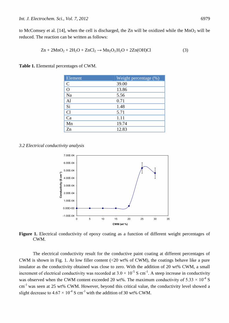
Figure 1. Electrical conductivity of epoxy coating as a function of different weight percentages of
CWM.
The electrical conductivity result for the conductive paint coating at different percentages of
CWM is shown in Fig. 1. At low filler content (<20 wt% of CWM), the coatings behave like a pure
insulator as the conductivity obtained was close to zero. With the addition of 20 wt% CWM, a small
increment of electrical conductivity was recorded at 3.0 × 10⁻⁵
S cm-1
. A steep increase in conductivity
was observed when the CWM content exceeded 20 wt%. The maximum conductivity of 5.33 × 10⁻⁴
S
cm-1
was seen at 25 wt% CWM. However, beyond this critical value, the conductivity level showed a
slight decrease to 4.67 × 10⁻⁴
S cm-1
with the addition of 30 wt% CWM.
Int. J. Electrochem. Sci., Vol. 7, 2012
6980
The maximum conductivity value achieved at 25 wt% CWM was consistent with the work
done by Tsotra et al. [12], who obtained an electrical conductivity of the order of 10-4
S cm-1
with the
addition of carbon fibre as the conductive pigment. Besides that, Masri et al. [5] also achieved a
maximum value of conductivity in the range of 10-4
S cm-1
with the addition of 20 wt% carbon black
additive. This indicates that CWM acts successfully as filler and improves the electrical conductivity at
the optimum weight percentage of 25 wt% CWM, which is comparable with other conductive filler
filled polymers.
2
Fig. 2: Image of (a) bare mild steel, (b) plain epoxy, (c) 10, (d) 20, (e) 25 and (f) 30 wt %
CWM-epoxy resin conductive coating after dried at room temperature for 24 hours.
(a) (c) (b)
1 cm Fine voids
(d) (e) (f)
Group of large voids
1 cm
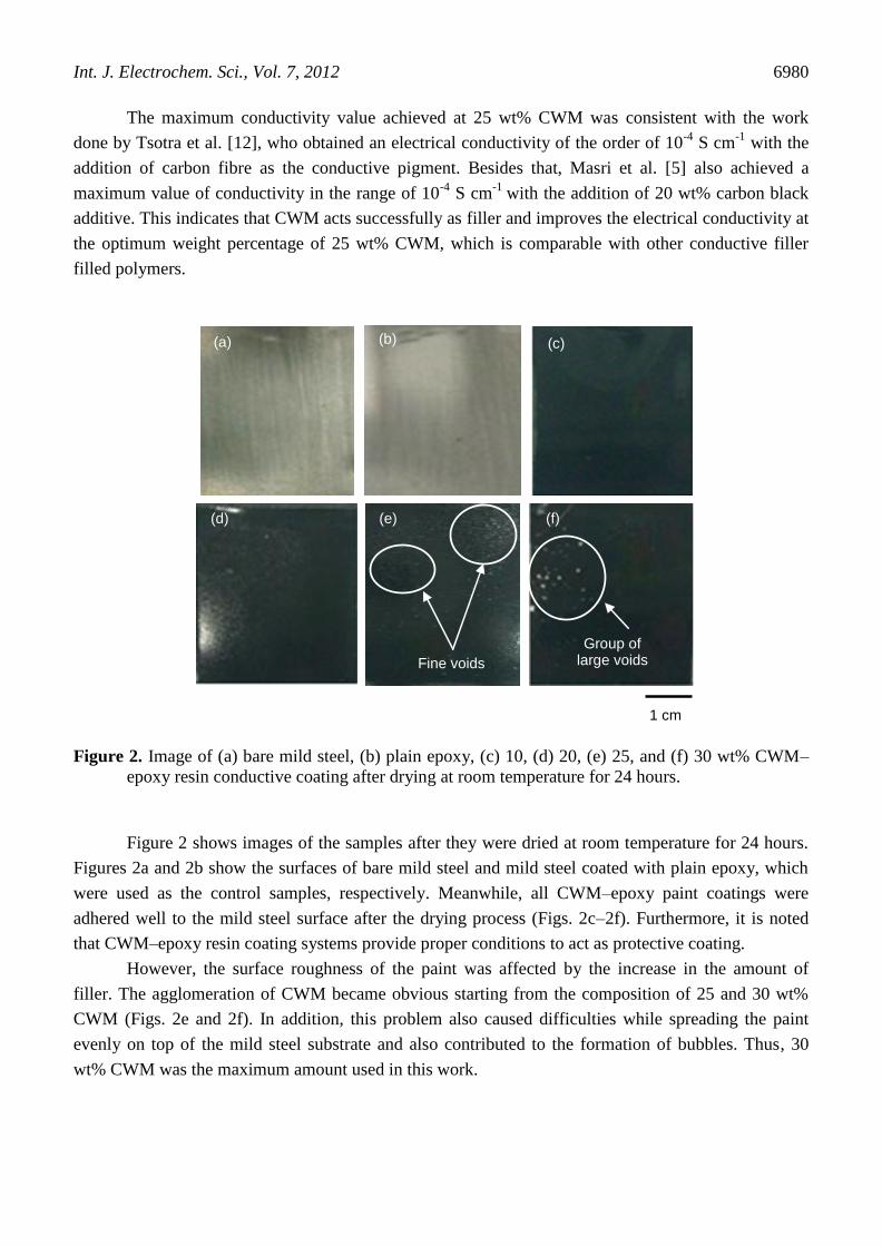
Figure 2. Image of (a) bare mild steel, (b) plain epoxy, (c) 10, (d) 20, (e) 25, and (f) 30 wt% CWM–
epoxy resin conductive coating after drying at room temperature for 24 hours.
Figure 2 shows images of the samples after they were dried at room temperature for 24 hours.
Figures 2a and 2b show the surfaces of bare mild steel and mild steel coated with plain epoxy, which
were used as the control samples, respectively. Meanwhile, all CWM–epoxy paint coatings were
adhered well to the mild steel surface after the drying process (Figs. 2c–2f). Furthermore, it is noted
that CWM–epoxy resin coating systems provide proper conditions to act as protective coating.
However, the surface roughness of the paint was affected by the increase in the amount of
filler. The agglomeration of CWM became obvious starting from the composition of 25 and 30 wt%
CWM (Figs. 2e and 2f). In addition, this problem also caused difficulties while spreading the paint
evenly on top of the mild steel substrate and also contributed to the formation of bubbles. Thus, 30
wt% CWM was the maximum amount used in this work.
Int. J. Electrochem. Sci., Vol. 7, 2012
6981
3
Fig 3: FESEM morphology images of surface polished CWM-epoxy resin coating at (a)
bare mild steel, (b) plain epoxy, (c) 10, (d) 20, (e) 25 and (f) 30 wt % CWM.
(b) (c)
(d)
40 µm
(f)
(a)
(e) Connected CWM
Agglomerated CWM
Connected CWM
Agglomerated CWM
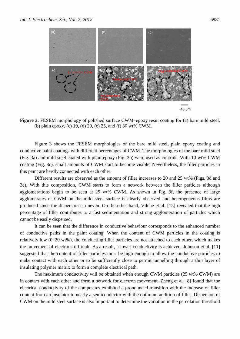
Figure 3. FESEM morphology of polished surface CWM–epoxy resin coating for (a) bare mild steel,
(b) plain epoxy, (c) 10, (d) 20, (e) 25, and (f) 30 wt% CWM.
Figure 3 shows the FESEM morphologies of the bare mild steel, plain epoxy coating and
conductive paint coatings with different percentages of CWM. The morphologies of the bare mild steel
(Fig. 3a) and mild steel coated with plain epoxy (Fig. 3b) were used as controls. With 10 wt% CWM
coating (Fig. 3c), small amounts of CWM start to become visible. Nevertheless, the filler particles in
this paint are hardly connected with each other.
Different results are observed as the amount of filler increases to 20 and 25 wt% (Figs. 3d and
3e). With this composition, CWM starts to form a network between the filler particles although
agglomerations begin to be seen at 25 wt% CWM. As shown in Fig. 3f, the presence of large
agglomerates of CWM on the mild steel surface is clearly observed and heterogeneous films are
produced since the dispersion is uneven. On the other hand, Vilche et al. [15] revealed that the high
percentage of filler contributes to a fast sedimentation and strong agglomeration of particles which
cannot be easily dispersed.
It can be seen that the difference in conductive behaviour corresponds to the enhanced number
of conductive paths in the paint coating. When the content of CWM particles in the coating is
relatively low (0–20 wt%), the conducting filler particles are not attached to each other, which makes
the movement of electrons difficult. As a result, a lower conductivity is achieved. Johnson et al. [11]
suggested that the content of filler particles must be high enough to allow the conductive particles to
make contact with each other or to be sufficiently close to permit tunnelling through a thin layer of
insulating polymer matrix to form a complete electrical path.
The maximum conductivity will be obtained when enough CWM particles (25 wt% CWM) are
in contact with each other and form a network for electron movement. Zheng et al. [8] found that the
electrical conductivity of the composites exhibited a pronounced transition with the increase of filler
content from an insulator to nearly a semiconductor with the optimum addition of filler. Dispersion of
CWM on the mild steel surface is also important to determine the variation in the percolation threshold
Int. J. Electrochem. Sci., Vol. 7, 2012
6982
for the conductivity transition [7]. Based on the measurements performed, it is possible to state that
coating containing about 25 wt% CWM exhibits satisfactory electrical conductivity properties.
3.3 Open circuit potential analysis
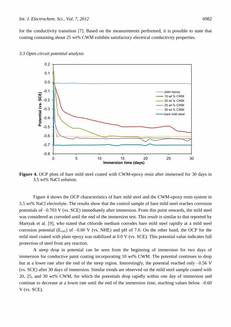
Figure 4. OCP plots of bare mild steel coated with CWM-epoxy resin after immersed for 30 days in
3.5 wt% NaCl solution.
Figure 4 shows the OCP characteristics of bare mild steel and the CWM-epoxy resin system in
3.5 wt% NaCl electrolyte. The results show that the control sample of bare mild steel reaches corrosion
potentials of –0.703 V (vs. SCE) immediately after immersion. From this point onwards, the mild steel
was considered as corroded until the end of the immersion test. This result is similar to that reported by
Martyak et al. [9], who stated that chloride medium corrodes bare mild steel rapidly at a mild steel
corrosion potential (Ecorr) of –0.60 V (vs. NHE) and pH of 7.0. On the other hand, the OCP for the
mild steel coated with plain epoxy was stabilized at 0.0 V (vs. SCE). This potential value indicates full
protection of steel from any reaction.
A steep drop in potential can be seen from the beginning of immersion for two days of
immersion for conductive paint coating incorporating 10 wt% CWM. The potential continues to drop
but at a lower rate after the end of the steep region. Interestingly, the potential reached only –0.56 V
(vs. SCE) after 30 days of immersion. Similar trends are observed on the mild steel sample coated with
20, 25, and 30 wt% CWM, for which the potentials drop rapidly within one day of immersion and
continue to decrease at a lower rate until the end of the immersion time, reaching values below –0.60
V (vs. SCE).
Int. J. Electrochem. Sci., Vol. 7, 2012
6983
It is noticeable that at the higher percentages of CWM content, the measured electrode potential
values drop quickly to reach the Ecorr of bare mild steel. At this stage, only the 10 wt% CWM–epoxy
resin system coating formulation was able to protect the mild steel for approximately 30 days
compared to the other CWM–epoxy resin systems. This shows that the penetration of the corrosive
ions into this coating system is minimal at 10 wt% CWM. As the main element in the CWM
compound, carbon is known to be porous and to possess a large surface area that is available for
adsorption of electrolyte [14]. Therefore, as the CWM particles increase, the conductive paint coating
tends to have higher porosity. Hence more electrolyte will penetrate the polymeric barrier and come
into contact with the steel surface, causing the mild steel to be corroded. A similar result has been
reported by Marchebois et al. [6], who found that when an increase in porosity is induced by the
addition of carbon black, it resulted in rapid penetration of electrolyte toward the substrate.
3.4 Morphological analysis
5
Fig. 5: Image of (a) bare mild steel, (b) plain epoxy, (c) 10, (d) 20, (e) 25 and (f) 30 wt %
CWM-epoxy resin conductive coating after being exposed to 3.5 wt % NaCl solution in
the OCP analysis.
(a) (c) (b)
(e) (d) (f)
1 cm
Corrosion spots
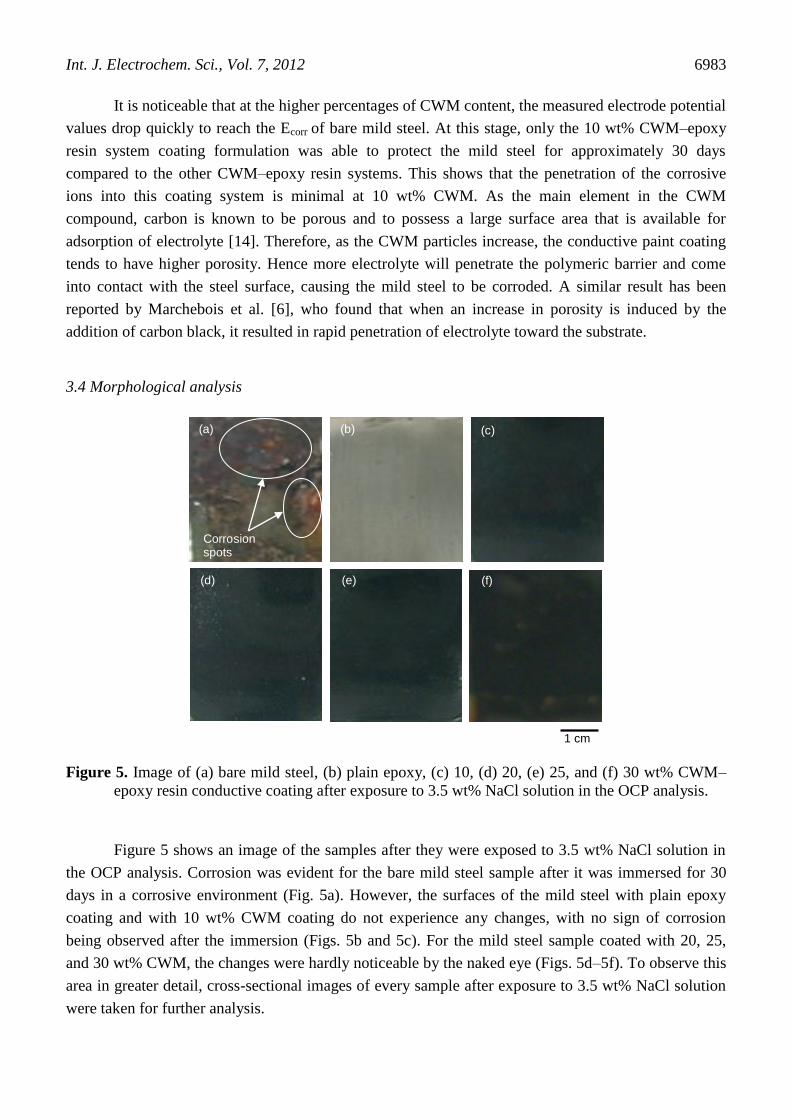
Figure 5. Image of (a) bare mild steel, (b) plain epoxy, (c) 10, (d) 20, (e) 25, and (f) 30 wt% CWM–
epoxy resin conductive coating after exposure to 3.5 wt% NaCl solution in the OCP analysis.
Figure 5 shows an image of the samples after they were exposed to 3.5 wt% NaCl solution in
the OCP analysis. Corrosion was evident for the bare mild steel sample after it was immersed for 30
days in a corrosive environment (Fig. 5a). However, the surfaces of the mild steel with plain epoxy
coating and with 10 wt% CWM coating do not experience any changes, with no sign of corrosion
being observed after the immersion (Figs. 5b and 5c). For the mild steel sample coated with 20, 25,
and 30 wt% CWM, the changes were hardly noticeable by the naked eye (Figs. 5d–5f). To observe this
area in greater detail, cross-sectional images of every sample after exposure to 3.5 wt% NaCl solution
were taken for further analysis.
Int. J. Electrochem. Sci., Vol. 7, 2012
6984
6
Fig. 6: Cross section image of (a) bare mild steel, (b) plain epoxy, (c) 10, (d) 20, (e) 25
and (f) 30 wt % CWM-epoxy resin conductive coating after being exposed to 3.5 wt %
NaCl solution in the OCP analysis.
Localized corrosion spot
1 mm
Localized corrosion spot
Localized corrosion spot
(a) (b) (c)
(d) (e) (f)
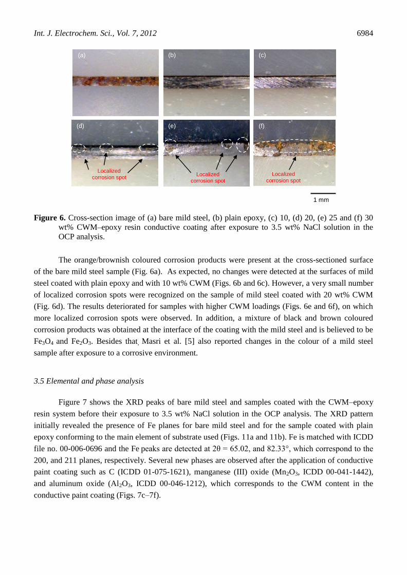
Figure 6. Cross-section image of (a) bare mild steel, (b) plain epoxy, (c) 10, (d) 20, (e) 25 and (f) 30
wt% CWM–epoxy resin conductive coating after exposure to 3.5 wt% NaCl solution in the
OCP analysis.
The orange/brownish coloured corrosion products were present at the cross-sectioned surface
of the bare mild steel sample (Fig. 6a). As expected, no changes were detected at the surfaces of mild
steel coated with plain epoxy and with 10 wt% CWM (Figs. 6b and 6c). However, a very small number
of localized corrosion spots were recognized on the sample of mild steel coated with 20 wt% CWM
(Fig. 6d). The results deteriorated for samples with higher CWM loadings (Figs. 6e and 6f), on which
more localized corrosion spots were observed. In addition, a mixture of black and brown coloured
corrosion products was obtained at the interface of the coating with the mild steel and is believed to be
Fe3O4 and Fe2O3. Besides that, Masri et al. [5] also reported changes in the colour of a mild steel
sample after exposure to a corrosive environment.
3.5 Elemental and phase analysis
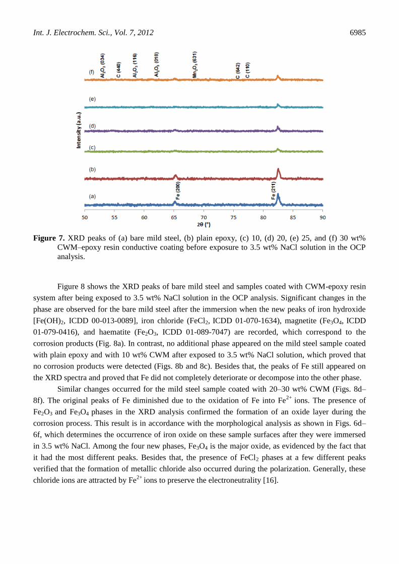
Figure 7 shows the XRD peaks of bare mild steel and samples coated with the CWM–epoxy
resin system before their exposure to 3.5 wt% NaCl solution in the OCP analysis. The XRD pattern
initially revealed the presence of Fe planes for bare mild steel and for the sample coated with plain
epoxy conforming to the main element of substrate used (Figs. 11a and 11b). Fe is matched with ICDD
file no. 00-006-0696 and the Fe peaks are detected at 2θ = 65.02, and 82.33°, which correspond to the
200, and 211 planes, respectively. Several new phases are observed after the application of conductive
paint coating such as C (ICDD 01-075-1621), manganese (III) oxide (Mn2O3, ICDD 00-041-1442),
and aluminum oxide (Al2O3, ICDD 00-046-1212), which corresponds to the CWM content in the
conductive paint coating (Figs. 7c–7f).
Int. J. Electrochem. Sci., Vol. 7, 2012
6985
Figure 7. XRD peaks of (a) bare mild steel, (b) plain epoxy, (c) 10, (d) 20, (e) 25, and (f) 30 wt%
CWM–epoxy resin conductive coating before exposure to 3.5 wt% NaCl solution in the OCP
analysis.
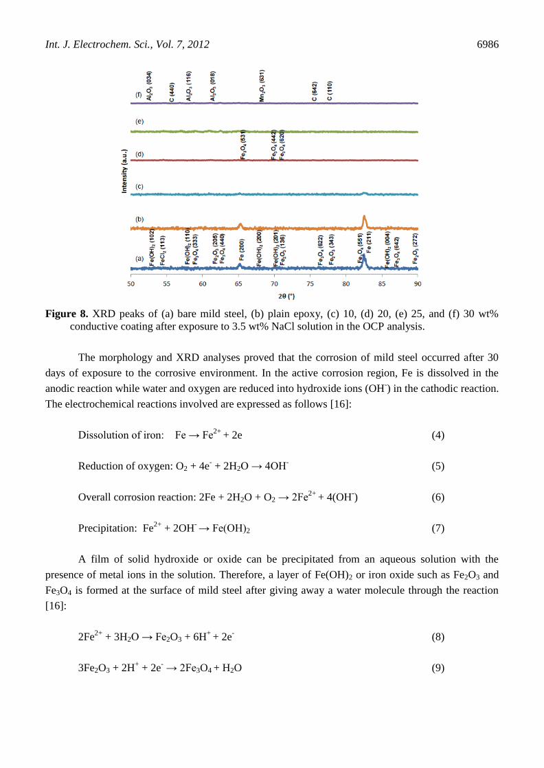
Figure 8 shows the XRD peaks of bare mild steel and samples coated with CWM-epoxy resin
system after being exposed to 3.5 wt% NaCl solution in the OCP analysis. Significant changes in the
phase are observed for the bare mild steel after the immersion when the new peaks of iron hydroxide
[Fe(OH)2, ICDD 00-013-0089], iron chloride (FeCl2, ICDD 01-070-1634), magnetite (Fe3O4, ICDD
01-079-0416), and haematite (Fe2O3, ICDD 01-089-7047) are recorded, which correspond to the
corrosion products (Fig. 8a). In contrast, no additional phase appeared on the mild steel sample coated
with plain epoxy and with 10 wt% CWM after exposed to 3.5 wt% NaCl solution, which proved that
no corrosion products were detected (Figs. 8b and 8c). Besides that, the peaks of Fe still appeared on
the XRD spectra and proved that Fe did not completely deteriorate or decompose into the other phase.
Similar changes occurred for the mild steel sample coated with 20–30 wt% CWM (Figs. 8d–
8f). The original peaks of Fe diminished due to the oxidation of Fe into Fe2+
ions. The presence of
Fe2O3 and Fe3O4 phases in the XRD analysis confirmed the formation of an oxide layer during the
corrosion process. This result is in accordance with the morphological analysis as shown in Figs. 6d–
6f, which determines the occurrence of iron oxide on these sample surfaces after they were immersed
in 3.5 wt% NaCl. Among the four new phases, Fe3O4 is the major oxide, as evidenced by the fact that
it had the most different peaks. Besides that, the presence of FeCl2 phases at a few different peaks
verified that the formation of metallic chloride also occurred during the polarization. Generally, these
chloride ions are attracted by Fe2+
ions to preserve the electroneutrality [16].
Int. J. Electrochem. Sci., Vol. 7, 2012
6986
Figure 8. XRD peaks of (a) bare mild steel, (b) plain epoxy, (c) 10, (d) 20, (e) 25, and (f) 30 wt%
conductive coating after exposure to 3.5 wt% NaCl solution in the OCP analysis.
The morphology and XRD analyses proved that the corrosion of mild steel occurred after 30
days of exposure to the corrosive environment. In the active corrosion region, Fe is dissolved in the
anodic reaction while water and oxygen are reduced into hydroxide ions (OH-) in the cathodic reaction.
The electrochemical reactions involved are expressed as follows [16]:
Dissolution of iron: Fe → Fe2+
+ 2e (4)
Reduction of oxygen: O2 + 4e- + 2H2O → 4OH
- (5)
Overall corrosion reaction: 2Fe + 2H2O + O2 → 2Fe2+
+ 4(OH-) (6)
Precipitation: Fe2+
+ 2OH- → Fe(OH)2 (7)
A film of solid hydroxide or oxide can be precipitated from an aqueous solution with the
presence of metal ions in the solution. Therefore, a layer of Fe(OH)2 or iron oxide such as Fe2O3 and
Fe3O4 is formed at the surface of mild steel after giving away a water molecule through the reaction
[16]:
2Fe2+
+ 3H2O → Fe2O3 + 6H+
+ 2e-
(8)
3Fe2O3 + 2H+ + 2e
- → 2Fe3O4
+ H2O (9)
Int. J. Electrochem. Sci., Vol. 7, 2012
6987
As a result, it is clearly indicated that only the mild steel sample coated with plain epoxy and
with 10 wt% CWM can provide significant corrosion protection after 30 days of immersion in 3.5 wt%
NaCl solutions.
4. CONCLUSIONS
The electrochemical properties of the conductive paint coatings depend on the content of CWM
and the homogeneity of the surface of the coating. The addition of CWM improved the electrical
conductivity with the maximum conductivity of 5.33 × 10⁻⁴
S cm-1
being obtained at 25 wt% CWM.
Morphology scans show that the increase in conductivity was due to the distribution of filler, which
allows electrons to flow either by direct physical contact of the filler particles or by a tunnelling effect
for a length of a few nanometres. However, a reduction of corrosion potential was obtained in the
corrosion analyses using high percentages of filler. The addition of CWM also increased the porosity
of the conductive paint. Thus, it is shown that the addition of CWM content had opposing effects on
the CWM–epoxy resin coating system when the high conductivity value contributed to the lowering of
the corrosion resistance of the coated mild steel.
ACKNOWLEDGEMENTS
The authors would like to thank USM for financial support of this study through grant RUI-814112.
References
1. L. Mathivanan, S. Radhakrishna, Anti-Corros. Methods Mater., 45 (1998) 301-305.
2. E. Armelin, R. Pla, F. Liesa, X. Ramis, J.I. Iribarren, C. Aleman, Corrosion Sci., 50 (2008) 721-
728.
3. S.S. Azim, A. Satheesh, K.K. Ramu, S. Ramu, G. Venkatachari, Prog. Org. Coat., 55 (2006) 1-4.
4. F. El-Tantawy, K. Kamada, H. Ohnabe, Mater. Lett., 56 (2002) 112-126.
5. M.N. Masri, Z.M. Z.M. Yunus, A.R.M. Warikh, A.A. Mohamad, Anti-Corros. Methods Mater., 57
(2010) 204-208.
6. H. Marchebois, S. Touzain, S. Joiret, J. Bernard, C. Savall, Prog. Org. Coat., 45 (2002) 415-421.
7. J. Orlikowski, S. Cebulski, K. Darowicki, Cem. Concr. Compos., 26 (2004) 721-728.
8. W. Zheng, S.-C. Wong, Compos. Sci. Technol., 63 (2003) 225-235.
9. N.M. Martyak, P. McAndrew, Corrosion Sci., 49 (2007) 3826-3837.
10. S.K. Shukla, M.A. Quraishi, R. Prakash, Corrosion Sci., 50 (2008) 2867-2872.
11. J.A. Johnson, M.J. Barbato, S.R. Hopkins, M.J. O'Malley, Prog. Org. Coat., 47 (2003) 198-206.
12. P. Tsotra, K. Friedrich, Compos. Sci. Technol., 64 (2004) 2385-2391.
13. M.B.J.G. Freitas, M.K. de Pietre, J. Power Sources, 143 (2005) 270-274.
14. D.W. McComsey, Zinc-carbon batteries (Leclanche and Zinc Chloride Cell System), in:
Handbook of batteries, D. Linden, T. B. Reddy, New York, 2001, pp. 8.1-8.45.
15. J.R. Vilche, E.C. Bucharsky, C.A. Giudice, Corrosion Sci., 44 (2002) 1287-1309.
16. Z. Ahmad, Principles of Corrosion Engineering And Corrosion Control, UK, Elsevier/BH, 2006.
© 2012 by ESG (www.electrochemsci.org)