
Datasheet Fluke 5790B. Hubungi PT. Siwali Swantika 021-45850618
Upload
pt-siwali-swantikaCategory
view
72download
2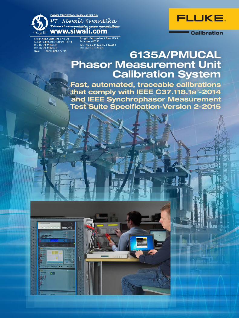
6135A/PMUCAL Phasor Measurement Unit
Calibration SystemFast, automated, traceable calibrations that comply with IEEE C37.118.1aTM-2014 and IEEE Synchrophasor Measurement Test Suite Specification-Version 2-2015
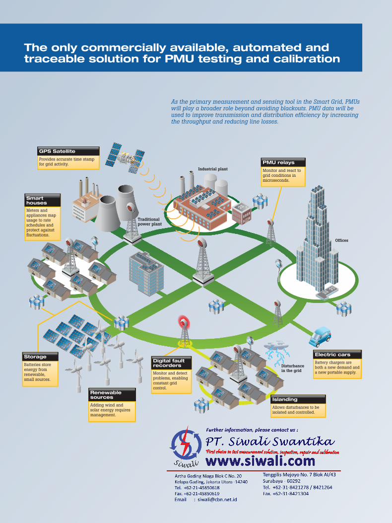
Smart houses
Meters and appliances map usage to rate schedules and protect against fluctuations.
PMU relays
Monitor and react to grid conditions in microseconds.
Islanding
Allows disturbances to be isolated and controlled.
Renewable sources
Adding wind and solar energy requires management.
Disturbancein the grid
Offices
Industrial plant
Traditionalpower plant
Digital fault recorders
Monitor and detect problems, enabling constant grid control.
Smart GridA real-time, dynamic network of electrical demand, supply, and control
Storage
Batteries store energy from renewable, small sources.
Electric cars
Battery chargers are both a new demand and a new portable supply.
GPS Satellite
Provides accurate time stamp for grid activity.
As the primary measurement and sensing tool in the Smart Grid, PMUs will play a broader role beyond avoiding blackouts. PMU data will be used to improve transmission and distribution efficiency by increasing the throughput and reducing line losses.
The only commercially available, automated and traceable solution for PMU testing and calibration
Today’s smart grid relies on phasor measurement units (PMUs) to deliver real-time, mission critical data on the voltage, current, frequency and phase within the distribution grid. To ensure consistent, accurate and credible PMU data, it is essential that PMUs be properly calibrated.
The 6135A/PMUCAL Phasor Measurement Unit Calibration System is the only fully automated and traceable PMU calibration system available today. It is an ideal solution for PMU designers and manufacturers, as well as for national metrology institutes (NMIs). It’s also a perfect solution for third party calibration houses, electrical power utilities and organizations associated with electrical power transmission.
Applications include calibrating PMUs before they are installed, and as required throughout their operational life; performing type tests of PMUs and other power grid tools; and performing first article approvals. Because the 6135A includes a three-phase 6135A Electrical Power Calibration Standard, you can also use it to calibrate wide workload of electrical power and power quality test instruments.
The integrated 6135A/PMUCAL system fully complies to the IEEE C37.118.1a-2014, IEEE Synchrophasor Measurement Test Suite Specifica-tion-Version 2-2015 and C37.242-2013 standards for PMU operation and verification. The system also fully complies to the 2016 draft standard IEC/IEEE 60255-118 Ed.1. Because it is fully automated, even non-expert users can start using it quickly, performing a complete complement of required tests in just a few hours, as opposed to many days with manual techniques.
6135A/PMUCAL at a glanceThe 6135A/PMUCAL system enables you to:• Calibrate and test a PMU from
a client PC, either at the site of the test system or remotely over the Internet
• Quickly set up a PMU test • Speed through automated
calibration procedures• Provide the required static
and dynamic voltage and current conditions that occur in a power distribution grid specified by the standard
• Apply those signals to a phasor measurement unit
• Capture the PMU’s reported results
• Compare those results with the original stimulus
• Evaluate against the thresholds defined in IEEE Std C37.118.1a™-2014
• Create test reports, graphs and calibration certificates that can be readily printed or shared electronically
The only commercially available, automated and traceable solution for PMU testing and calibration
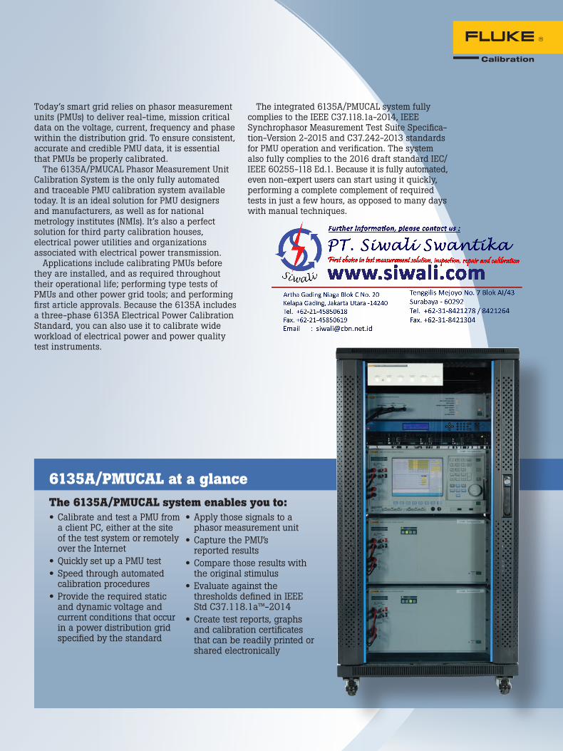
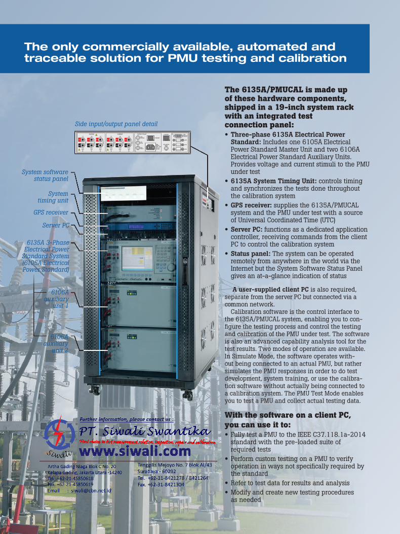
The 6135A/PMUCAL is made up of these hardware components, shipped in a 19-inch system rack with an integrated test connection panel:• Three-phase 6135A Electrical Power
Standard: Includes one 6105A Electrical Power Standard Master Unit and two 6106A Electrical Power Standard Auxiliary Units. Provides voltage and current stimuli to the PMU under test
• 6135A System Timing Unit: controls timing and synchronizes the tests done throughout the calibration system
• GPS receiver: supplies the 6135A/PMUCAL system and the PMU under test with a source of Universal Coordinated Time (UTC)
• Server PC: functions as a dedicated application controller, receiving commands from the client PC to control the calibration system
• Status panel: The system can be operated remotely from anywhere in the world via the Internet but the System Software Status Panel gives an at-a-glance indication of status
A user-supplied client PC is also required, separate from the server PC but connected via a common network.
Calibration software is the control interface to the 6135A/PMUCAL system, enabling you to con-figure the testing process and control the testing and calibration of the PMU under test. The software is also an advanced capability analysis tool for the test results. Two modes of operation are available. In Simulate Mode, the software operates with-out being connected to an actual PMU, but rather simulates the PMU responses in order to do test development, system training, or use the calibra-tion software without actually being connected to a calibration system. The PMU Test Mode enables you to test a PMU and collect actual testing data.
With the software on a client PC, you can use it to:• Fully test a PMU to the IEEE C37.118.1a-2014
standard with the pre-loaded suite of required tests
• Perform custom testing on a PMU to verify operation in ways not specifically required by the standard
• Refer to test data for results and analysis• Modify and create new testing procedures
as needed
Server PC
System timing unit
System software status panel
Side input/output panel detail
GPS receiver
6135A 3-Phase Electrical Power
Standard System (6105A Electrical Power Standard)
6106A auxiliary
unit 1
6106A auxiliary
unit 2
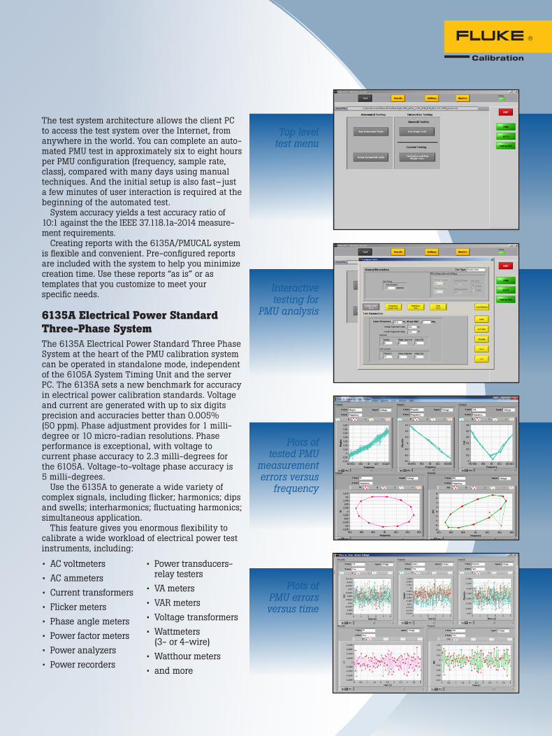
The test system architecture allows the client PC to access the test system over the Internet, from anywhere in the world. You can complete an auto-mated PMU test in approximately six to eight hours per PMU configuration (frequency, sample rate, class), compared with many days using manual techniques. And the initial setup is also fast– just a few minutes of user interaction is required at the beginning of the automated test.
System accuracy yields a test accuracy ratio of 10:1 against the the IEEE 37.118.1a-2014 measure-ment requirements.
Creating reports with the 6135A/PMUCAL system is flexible and convenient. Pre-configured reports are included with the system to help you minimize creation time. Use these reports “as is” or as templates that you customize to meet your specific needs.
6135A Electrical Power Standard Three-Phase SystemThe 6135A Electrical Power Standard Three Phase System at the heart of the PMU calibration system can be operated in standalone mode, independent of the 6105A System Timing Unit and the server PC. The 6135A sets a new benchmark for accuracy in electrical power calibration standards. Voltage and current are generated with up to six digits precision and accuracies better than 0.005% (50 ppm). Phase adjustment provides for 1 milli-degree or 10 micro-radian resolutions. Phase performance is exceptional, with voltage to current phase accuracy to 2.3 milli-degrees for the 6105A. Voltage-to-voltage phase accuracy is 5 milli-degrees.
Use the 6135A to generate a wide variety of complex signals, including flicker; harmonics; dips and swells; interharmonics; fluctuating harmonics; simultaneous application.
This feature gives you enormous flexibility to calibrate a wide workload of electrical power test instruments, including:
• AC voltmeters• AC ammeters• Current transformers• Flicker meters• Phase angle meters• Power factor meters• Power analyzers• Power recorders
• Power transducers-relay testers
• VA meters• VAR meters• Voltage transformers• Wattmeters
(3- or 4-wire)• Watthour meters• and more
Top level test menu
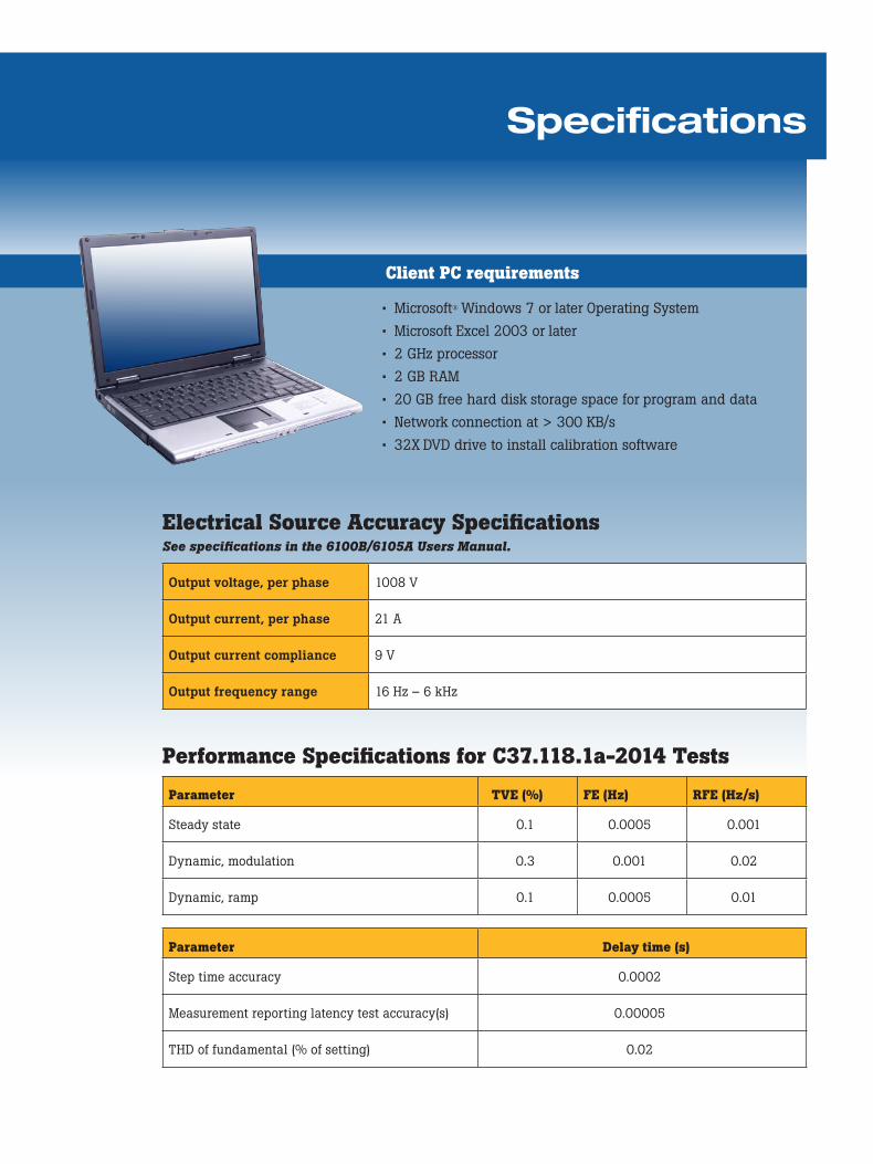
Interactive testing for
PMU analysis
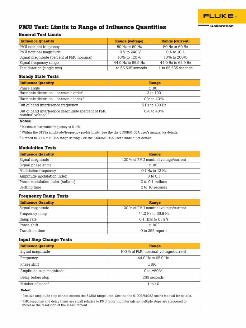
Plots of tested PMU
measurement errors versus
frequency
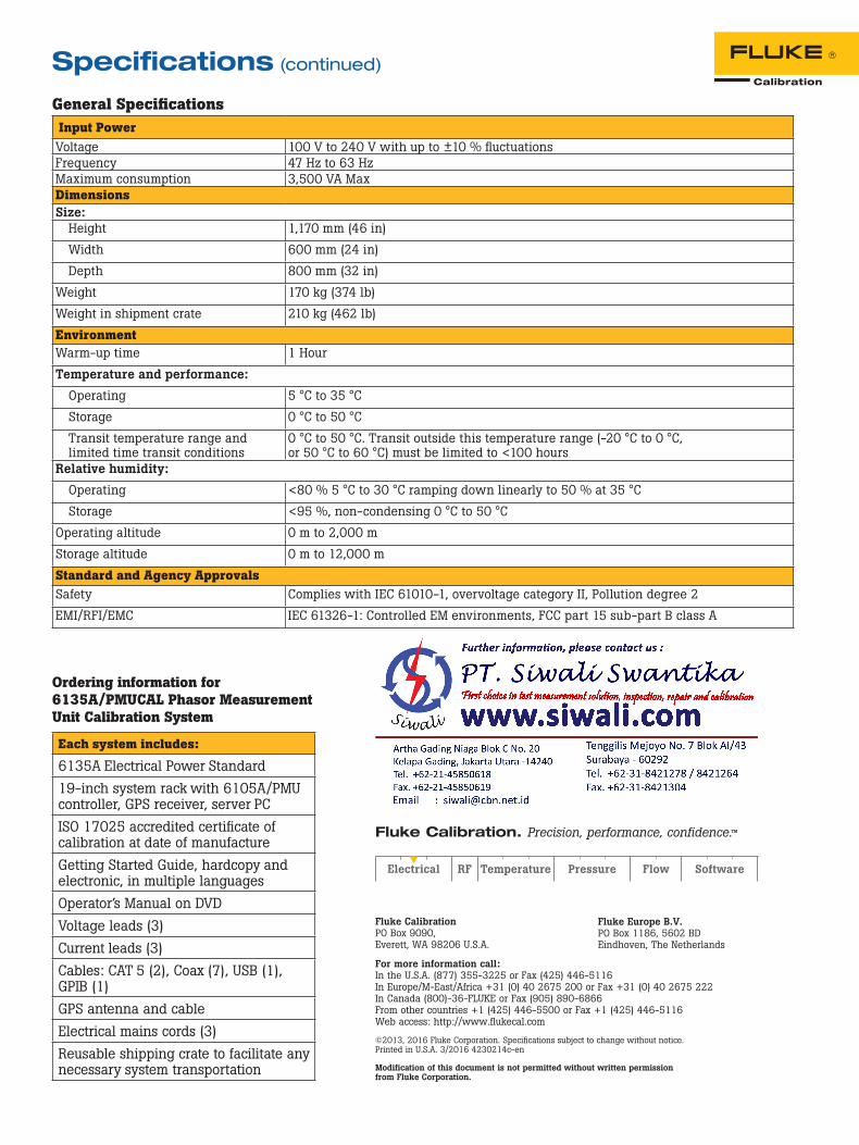
Plots of PMU errors versus time
Specifications
Client PC requirements
Electrical Source Accuracy SpecificationsSee specifications in the 6100B/6105A Users Manual.
Output voltage, per phase 1008 V
Output current, per phase 21 A
Output current compliance 9 V
Output frequency range 16 Hz – 6 kHz
Performance Specifications for C37.118.1a-2014 Tests
Parameter TVE (%) FE (Hz) RFE (Hz/s)
Steady state 0.1 0.0005 0.001
Dynamic, modulation 0.3 0.001 0.02
Dynamic, ramp 0.1 0.0005 0.01
Parameter Delay time (s)
Step time accuracy 0.0002
Measurement reporting latency test accuracy(s) 0.00005
THD of fundamental (% of setting) 0.02
• Microsoft® Windows 7 or later Operating System• Microsoft Excel 2003 or later• 2 GHz processor• 2 GB RAM• 20 GB free hard disk storage space for program and data• Network connection at > 300 KB/s• 32X DVD drive to install calibration software
Client PC requirements
PMU Test: Limits to Range of Influence QuantitiesGeneral Test LimitsInfluence Quantity Range (voltage) Range (current)PMU nominal frequency 50 Hz or 60 Hz 50 Hz or 60 HzPMU nominal magnitude 10 V to 240 V 0 A to 10 ASignal magnitude (percent of PMU nominal) 10 % to 120 % 10 % to 200%Signal frequency range 44.0 Hz to 65.9 Hz 44.0 Hz to 65.9 HzTest duration (single test) 1 to 65,535 seconds 1 to 65,535 seconds
Steady State Tests
Influence Quantity RangePhase angle ±180 ˚Harmonic distortion - harmonic order1 2 to 100
Harmonic distortion - harmonic index2 0% to 40%
Out of band interference frequency 5 Hz to 180 Hz
Out of band interference magnitude (percent of PMU nominal voltage) 3
0% to 40 %
Notes: 1 Maximum harmonic frequency is 6 kHz.2 Within the 6135a amplitude/frequency profile limits. See the the 6100B/6105A user’s manual for details.3 Limited to 30% of 6135A range setting. See the 6100B/6105A user’s manual for details.
Modulation TestsInfluence Quantity RangeSignal magnitude 100 % of PMU nominal voltage/currentSignal phase angle ±180 ˚Modulation frequency 0.1 Hz to 12 HzAmplitude modulation index 0 to 0.1Phase modulation index (radians) 0 to 0.1 radiansSettling time 0 to 10 seconds
Frequency Ramp TestsInfluence Quantity RangeSignal magnitude 100 % of PMU nominal voltage/currentFrequency ramp 44.0 Hz to 65.9 HzRamp rate 0.1 Hz/s to 6 Hz/sPhase shift ±180 ˚Transition time 0 to 255 reports
Input Step Change TestsInfluence Quantity RangeSignal magnitude 100 % of PMU nominal voltage/currentFrequency 44.0 Hz to 65.9 Hz
Phase shift ±180 ˚
Amplitude step magnitude1 0 to ±50 %
Delay before step 255 seconds
Number of steps2 1 to 40
Notes: 1 Positive amplitude step cannot exceed the 6135A range limit. See the the 6100B/6105A user’s manual for details.2 PMU response and delay times are small relative to PMU reporting intervals so multiple steps are staggered to increase the resolution of the measurement.
Fluke Calibration PO Box 9090, Everett, WA 98206 U.S.A.
Fluke Europe B.V. PO Box 1186, 5602 BD Eindhoven, The Netherlands
For more information call: In the U.S.A. (877) 355-3225 or Fax (425) 446-5116 In Europe/M-East/Africa +31 (0) 40 2675 200 or Fax +31 (0) 40 2675 222 In Canada (800)-36-FLUKE or Fax (905) 890-6866 From other countries +1 (425) 446-5500 or Fax +1 (425) 446-5116 Web access: http://www.flukecal.com
©2013, 2016 Fluke Corporation. Specifications subject to change without notice. Printed in U.S.A. 3/2016 4230214c-en
Modification of this document is not permitted without written permission from Fluke Corporation.
Fluke Calibration. Precision, performance, confidence.™
General SpecificationsInput PowerVoltage 100 V to 240 V with up to ±10 % fluctuationsFrequency 47 Hz to 63 HzMaximum consumption 3,500 VA MaxDimensionsSize:
Height 1,170 mm (46 in)
Width 600 mm (24 in)
Depth 800 mm (32 in)
Weight 170 kg (374 lb)
Weight in shipment crate 210 kg (462 lb)
EnvironmentWarm-up time 1 Hour
Temperature and performance:
Operating 5 °C to 35 °C
Storage 0 °C to 50 °C
Transit temperature range and limited time transit conditions
0 °C to 50 °C. Transit outside this temperature range (-20 °C to 0 °C, or 50 °C to 60 °C) must be limited to <100 hours
Relative humidity:
Operating <80 % 5 °C to 30 °C ramping down linearly to 50 % at 35 °C
Storage <95 %, non-condensing 0 °C to 50 °C
Operating altitude 0 m to 2,000 m
Storage altitude 0 m to 12,000 m
Standard and Agency Approvals Safety Complies with IEC 61010-1, overvoltage category II, Pollution degree 2
EMI/RFI/EMC IEC 61326-1: Controlled EM environments, FCC part 15 sub-part B class A
Each system includes:
6135A Electrical Power Standard19-inch system rack with 6105A/PMU controller, GPS receiver, server PCISO 17025 accredited certificate of calibration at date of manufactureGetting Started Guide, hardcopy and electronic, in multiple languagesOperator’s Manual on DVDVoltage leads (3)Current leads (3)Cables: CAT 5 (2), Coax (7), USB (1), GPIB (1)GPS antenna and cableElectrical mains cords (3)Reusable shipping crate to facilitate any necessary system transportation
Ordering information for 6135A/PMUCAL Phasor Measurement Unit Calibration System
Specifications (continued)