FCC Test Report - UMTS Band 4 · FCC Test Report - UMTS Band 4 . Report ID: 03360-RF-00099. FCC ID...
23
FCC ID: AZ489FT7078 Report ID: 03360-RF-00099 1 FCC Test Report - UMTS Band 4 Report ID: 03360-RF-00099 FCC ID : AZ489FT7078 Tested Model : LEX L10i Test Date : Jan 13, 2016 ~ Feb 20, 2016 Issued Date : 26 Feb, 2016 Applicant : Motorola Solution Malaysia Sdn Bhd Address : Innoplex Plot 2A, Medan Bayan lepas, Mukim 12, S.W.D. 11900 Bayan Lepas, Penang, Malaysia Testing Lab : Motorola Penang Adv. Comm. Laboratory Lab Address : Motorola Solutions Malaysia Sdn Bhd, Plot 2, Bayan Lepas Technoplex Industrial Park, Mukim 12 S.W.D, 11900 Bayan Lepas, Penang, Malaysia. FCC Registration: 772092 Prepare By: __________________________, Date: ___26 Feb, 2016_ _____ Chan Choon Keet / Engineer / +6048503678 / [email protected] Approved By: _________________________, Date: ___26 Feb, 2016 ______ Alex Goh / Senior Staff Engineer /+6042527292 / [email protected]
Transcript of FCC Test Report - UMTS Band 4 · FCC Test Report - UMTS Band 4 . Report ID: 03360-RF-00099. FCC ID...
FCC ID: AZ489FT7078 Report ID: 03360-RF-00099
1
FCC Test Report - UMTS Band 4 Report ID: 03360-RF-00099 FCC ID : AZ489FT7078
Tested Model : LEX L10i
Test Date : Jan 13, 2016 ~ Feb 20, 2016
Issued Date : 26 Feb, 2016
Applicant : Motorola Solution Malaysia Sdn Bhd
Address : Innoplex Plot 2A, Medan Bayan lepas, Mukim 12, S.W.D. 11900 Bayan Lepas, Penang, Malaysia
Testing Lab : Motorola Penang Adv. Comm. Laboratory
Lab Address : Motorola Solutions Malaysia Sdn Bhd, Plot 2, Bayan Lepas Technoplex Industrial Park, Mukim 12 S.W.D, 11900 Bayan Lepas, Penang, Malaysia.
FCC Registration: 772092
Prepare By: __________________________, Date: ___26 Feb, 2016______
Chan Choon Keet / Engineer / +6048503678 / [email protected]
Approved By: _________________________, Date: ___26 Feb, 2016______
Alex Goh / Senior Staff Engineer /+6042527292 / [email protected]
FCC ID: AZ489FT7078 Report ID: 03360-RF-00099
2
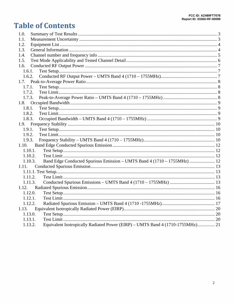
Table of Contents 1.0. Summary of Test Results ......................................................................................................................... 3 1.1. Measurement Uncertainty ........................................................................................................................ 3 1.2. Equipment List ......................................................................................................................................... 4 1.3. General Information ................................................................................................................................. 4 1.4. Channel number and frequency info ........................................................................................................ 5 1.5. Test Mode Applicability and Tested Channel Detail ............................................................................... 6 1.6. Conducted RF Output Power ................................................................................................................... 7
1.6.1. Test Setup.......................................................................................................................................... 7 1.6.2. Conducted RF Output Power – UMTS Band 4 (1710 – 1755MHz) ................................................. 7
1.7. Peak-to-Average Power Ratio .................................................................................................................. 8 1.7.1. Test Setup.......................................................................................................................................... 8 1.7.2. Test Limit .......................................................................................................................................... 8 1.7.3. Peak-to-Average Power Ratio – UMTS Band 4 (1710 – 1755MHz) ............................................... 8
1.8. Occupied Bandwidth ................................................................................................................................ 9 1.8.1. Test Setup.......................................................................................................................................... 9 1.8.2. Test Limit .......................................................................................................................................... 9 1.8.3. Occupied Bandwidth – UMTS Band 4 (1710 – 1755MHz) ............................................................. 9
1.9. Frequency Stability ................................................................................................................................ 10 1.9.1. Test Setup........................................................................................................................................ 10 1.9.2. Test Limit ........................................................................................................................................ 10 1.9.3. Frequency Stability – UMTS Band 4 (1710 – 1755MHz) .............................................................. 10
1.10. Band Edge Conducted Spurious Emission ......................................................................................... 12 1.10.1. Test Setup .................................................................................................................................... 12 1.10.2. Test Limit .................................................................................................................................... 12 1.10.3. Band Edge Conducted Spurious Emission – UMTS Band 4 (1710 – 1755MHz) ...................... 12
1.11. Conducted Spurious Emission ............................................................................................................ 13 1.11.1. Test Setup.......................................................................................................................................... 13 1.11.2. Test Limit .................................................................................................................................... 13 1.11.3. Conducted Spurious Emissions – UMTS Band 4 (1710 – 1755MHz) ....................................... 13
1.12. Radiated Spurious Emission ............................................................................................................... 16 1.12.0. Test Setup .................................................................................................................................... 16 1.12.1. Test Limit .................................................................................................................................... 16 1.12.2. Radiated Spurious Emission – UMTS Band 4 (1710 -1755MHz) .............................................. 17
1.13. Equivalent Isotropically Radiated Power (EIRP) ............................................................................... 20 1.13.0. Test Setup .................................................................................................................................... 20 1.13.1. Test Limit .................................................................................................................................... 20 1.13.2. Equivalent Isotropically Radiated Power (EIRP) – UMTS Band 4 (1710-1755MHz) ............... 21
FCC ID: AZ489FT7078 Report ID: 03360-RF-00099
3
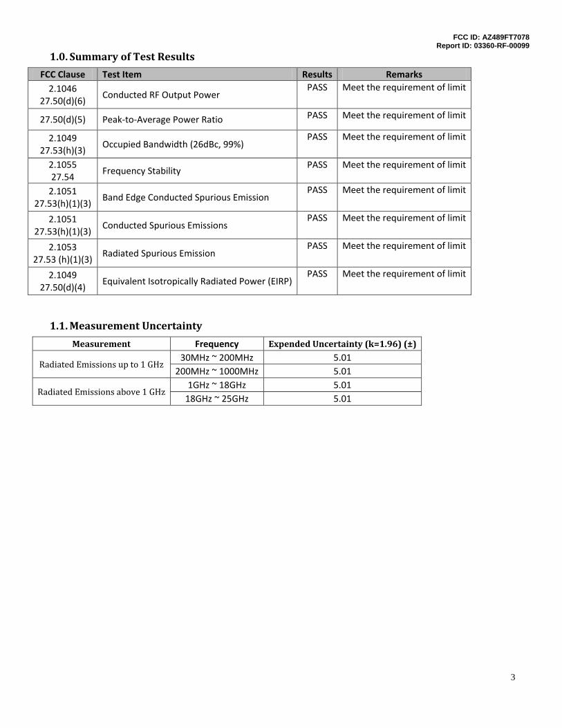
1.0. Summary of Test Results
FCC Clause Test Item Results Remarks 2.1046
27.50(d)(6) Conducted RF Output Power
PASS Meet the requirement of limit
27.50(d)(5) Peak-to-Average Power Ratio PASS Meet the requirement of limit
2.1049 27.53(h)(3)
Occupied Bandwidth (26dBc, 99%) PASS Meet the requirement of limit
2.1055 27.54
Frequency Stability PASS Meet the requirement of limit
2.1051 27.53(h)(1)(3)
Band Edge Conducted Spurious Emission PASS Meet the requirement of limit
2.1051 27.53(h)(1)(3)
Conducted Spurious Emissions PASS Meet the requirement of limit
2.1053 27.53 (h)(1)(3)
Radiated Spurious Emission PASS Meet the requirement of limit
2.1049 27.50(d)(4)
Equivalent Isotropically Radiated Power (EIRP) PASS Meet the requirement of limit
1.1. Measurement Uncertainty
Measurement Frequency Expended Uncertainty (k=1.96) (±)
Radiated Emissions up to 1 GHz 30MHz ~ 200MHz 5.01
200MHz ~ 1000MHz 5.01
Radiated Emissions above 1 GHz 1GHz ~ 18GHz 5.01
18GHz ~ 25GHz 5.01
FCC ID: AZ489FT7078 Report ID: 03360-RF-00099
4
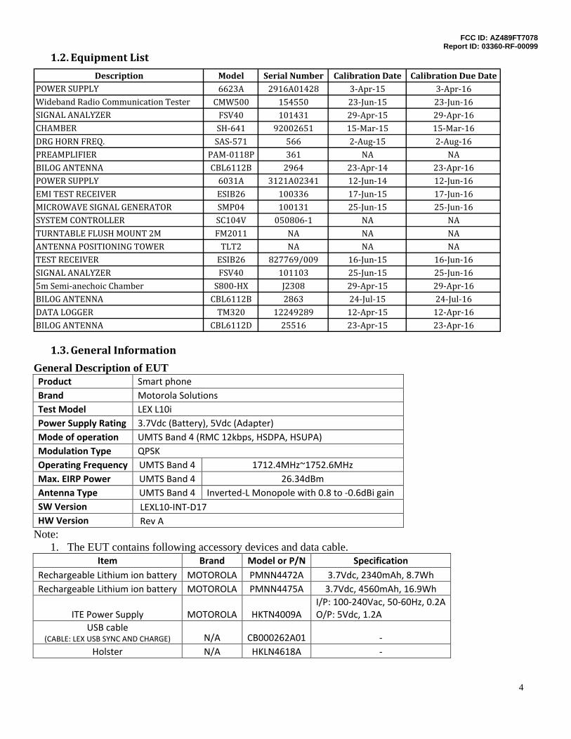
1.2. Equipment List
Description Model Serial Number Calibration Date Calibration Due DatePOWER SUPPLY 6623A 2916A01428 3-Apr-15 3-Apr-16Wideband Radio Communication Tester CMW500 154550 23-Jun-15 23-Jun-16SIGNAL ANALYZER FSV40 101431 29-Apr-15 29-Apr-16CHAMBER SH-641 92002651 15-Mar-15 15-Mar-16DRG HORN FREQ. SAS-571 566 2-Aug-15 2-Aug-16PREAMPLIFIER PAM-0118P 361 NA NABILOG ANTENNA CBL6112B 2964 23-Apr-14 23-Apr-16POWER SUPPLY 6031A 3121A02341 12-Jun-14 12-Jun-16EMI TEST RECEIVER ESIB26 100336 17-Jun-15 17-Jun-16MICROWAVE SIGNAL GENERATOR SMP04 100131 25-Jun-15 25-Jun-16SYSTEM CONTROLLER SC104V 050806-1 NA NATURNTABLE FLUSH MOUNT 2M FM2011 NA NA NAANTENNA POSITIONING TOWER TLT2 NA NA NATEST RECEIVER ESIB26 827769/009 16-Jun-15 16-Jun-16SIGNAL ANALYZER FSV40 101103 25-Jun-15 25-Jun-165m Semi-anechoic Chamber S800-HX J2308 29-Apr-15 29-Apr-16BILOG ANTENNA CBL6112B 2863 24-Jul-15 24-Jul-16DATA LOGGER TM320 12249289 12-Apr-15 12-Apr-16BILOG ANTENNA CBL6112D 25516 23-Apr-15 23-Apr-16
1.3. General Information
General Description of EUT Product Smart phone Brand Motorola Solutions Test Model LEX L10i Power Supply Rating 3.7Vdc (Battery), 5Vdc (Adapter) Mode of operation UMTS Band 4 (RMC 12kbps, HSDPA, HSUPA) Modulation Type QPSK Operating Frequency UMTS Band 4 1712.4MHz~1752.6MHz Max. EIRP Power UMTS Band 4 26.34dBm Antenna Type UMTS Band 4 Inverted-L Monopole with 0.8 to -0.6dBi gain SW Version LEXL10-INT-D17 HW Version Rev A
Note: 1. The EUT contains following accessory devices and data cable.
Item Brand Model or P/N Specification Rechargeable Lithium ion battery MOTOROLA PMNN4472A 3.7Vdc, 2340mAh, 8.7Wh Rechargeable Lithium ion battery MOTOROLA PMNN4475A 3.7Vdc, 4560mAh, 16.9Wh
ITE Power Supply MOTOROLA HKTN4009A I/P: 100-240Vac, 50-60Hz, 0.2A O/P: 5Vdc, 1.2A
USB cable (CABLE: LEX USB SYNC AND CHARGE) N/A CB000262A01 -
Holster N/A HKLN4618A -
FCC ID: AZ489FT7078 Report ID: 03360-RF-00099
5
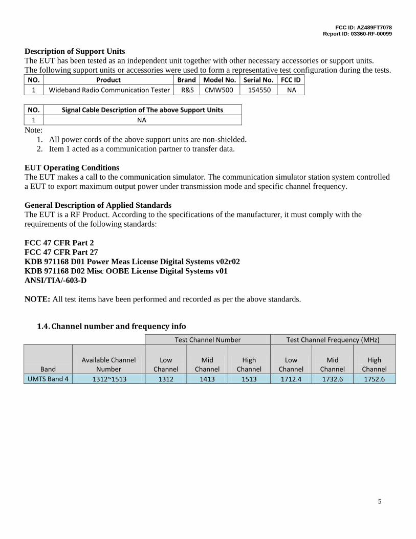
Description of Support Units The EUT has been tested as an independent unit together with other necessary accessories or support units. The following support units or accessories were used to form a representative test configuration during the tests. NO. Product Brand Model No. Serial No. FCC ID
1 Wideband Radio Communication Tester R&S CMW500 154550 NA NO. Signal Cable Description of The above Support Units
1 NA Note:
1. All power cords of the above support units are non-shielded. 2. Item 1 acted as a communication partner to transfer data.
EUT Operating Conditions The EUT makes a call to the communication simulator. The communication simulator station system controlled a EUT to export maximum output power under transmission mode and specific channel frequency.
General Description of Applied Standards The EUT is a RF Product. According to the specifications of the manufacturer, it must comply with the requirements of the following standards:
FCC 47 CFR Part 2 FCC 47 CFR Part 27 KDB 971168 D01 Power Meas License Digital Systems v02r02 KDB 971168 D02 Misc OOBE License Digital Systems v01 ANSI/TIA/-603-D NOTE: All test items have been performed and recorded as per the above standards.
1.4. Channel number and frequency info
Test Channel Number Test Channel Frequency (MHz)
Band Available Channel
Number Low
Channel Mid
Channel High
Channel Low
Channel Mid
Channel High
Channel UMTS Band 4 1312~1513 1312 1413 1513 1712.4 1732.6 1752.6
FCC ID: AZ489FT7078 Report ID: 03360-RF-00099
6
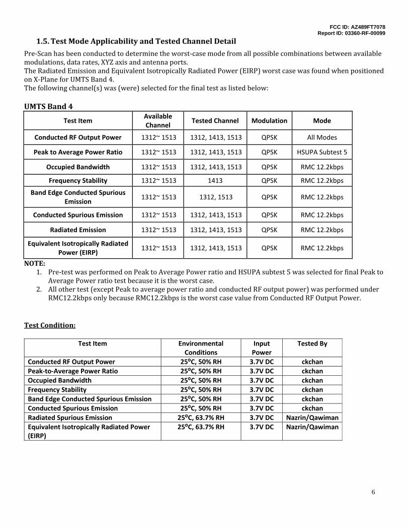
1.5. Test Mode Applicability and Tested Channel Detail
Pre-Scan has been conducted to determine the worst-case mode from all possible combinations between available modulations, data rates, XYZ axis and antenna ports. The Radiated Emission and Equivalent Isotropically Radiated Power (EIRP) worst case was found when positioned on X-Plane for UMTS Band 4. The following channel(s) was (were) selected for the final test as listed below: UMTS Band 4
Test Item Available Channel
Tested Channel Modulation Mode
Conducted RF Output Power 1312~ 1513 1312, 1413, 1513 QPSK All Modes
Peak to Average Power Ratio 1312~ 1513 1312, 1413, 1513 QPSK HSUPA Subtest 5
Occupied Bandwidth 1312~ 1513 1312, 1413, 1513 QPSK RMC 12.2kbps
Frequency Stability 1312~ 1513 1413 QPSK RMC 12.2kbps
Band Edge Conducted Spurious Emission
1312~ 1513 1312, 1513 QPSK RMC 12.2kbps
Conducted Spurious Emission 1312~ 1513 1312, 1413, 1513 QPSK RMC 12.2kbps
Radiated Emission 1312~ 1513 1312, 1413, 1513 QPSK RMC 12.2kbps
Equivalent Isotropically Radiated Power (EIRP)
1312~ 1513 1312, 1413, 1513 QPSK RMC 12.2kbps
NOTE: 1. Pre-test was performed on Peak to Average Power ratio and HSUPA subtest 5 was selected for final Peak to
Average Power ratio test because it is the worst case. 2. All other test (except Peak to average power ratio and conducted RF output power) was performed under
RMC12.2kbps only because RMC12.2kbps is the worst case value from Conducted RF Output Power. Test Condition:
Test Item Environmental Conditions
Input Power
Tested By
Conducted RF Output Power 25⁰C, 50% RH 3.7V DC ckchan Peak-to-Average Power Ratio 25⁰C, 50% RH 3.7V DC ckchan Occupied Bandwidth 25⁰C, 50% RH 3.7V DC ckchan Frequency Stability 25⁰C, 50% RH 3.7V DC ckchan Band Edge Conducted Spurious Emission 25⁰C, 50% RH 3.7V DC ckchan Conducted Spurious Emission 25⁰C, 50% RH 3.7V DC ckchan Radiated Spurious Emission 25⁰C, 63.7% RH 3.7V DC Nazrin/Qawiman Equivalent Isotropically Radiated Power (EIRP)
25⁰C, 63.7% RH 3.7V DC Nazrin/Qawiman
FCC ID: AZ489FT7078 Report ID: 03360-RF-00099
7
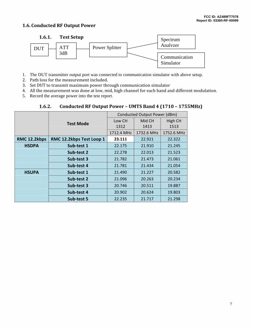
1.6. Conducted RF Output Power
1.6.1. Test Setup
1. The DUT transmitter output port was connected to communication simulator with above setup. 2. Path loss for the measurement included. 3. Set DUT to transmit maximum power through communication simulator 4. All the measurement was done at low, mid, high channel for each band and different modulation. 5. Record the average power into the test report.
1.6.2. Conducted RF Output Power – UMTS Band 4 (1710 – 1755MHz)
Test Mode
Conducted Output Power (dBm) Low CH
1312 Mid CH
1413 High CH
1513 1712.4 MHz 1732.6 MHz 1752.6 MHz
RMC 12.2kbps RMC 12.2kbps Test Loop 1 23.111 22.921 22.322
HSDPA Sub-test 1 22.175 21.910 21.245
Sub-test 2 22.278 22.013 21.523
Sub-test 3 21.782 21.473 21.061
Sub-test 4 21.781 21.434 21.054
HSUPA Sub-test 1 21.490 21.227 20.582
Sub-test 2 21.096 20.263 20.234
Sub-test 3 20.746 20.511 19.887
Sub-test 4 20.902 20.624 19.803
Sub-test 5 22.235 21.717 21.298
Communication Simulator
Spectrum Analyzer
DUT Power Splitter ATT 3dB
FCC ID: AZ489FT7078 Report ID: 03360-RF-00099
8
1.7. Peak-to-Average Power Ratio
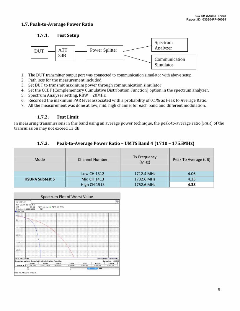
1.7.1. Test Setup
1. The DUT transmitter output port was connected to communication simulator with above setup. 2. Path loss for the measurement included. 3. Set DUT to transmit maximum power through communication simulator 4. Set the CCDF (Complementary Cumulative Distribution Function) option in the spectrum analyzer. 5. Spectrum Analyzer setting, RBW = 20MHz. 6. Recorded the maximum PAR level associated with a probability of 0.1% as Peak to Average Ratio. 7. All the measurement was done at low, mid, high channel for each band and different modulation.
1.7.2. Test Limit
In measuring transmissions in this band using an average power technique, the peak-to-average ratio (PAR) of the transmission may not exceed 13 dB.
1.7.3. Peak-to-Average Power Ratio – UMTS Band 4 (1710 – 1755MHz)
Mode Channel Number Tx Frequency
(MHz) Peak To Average (dB)
HSUPA Subtest 5 Low CH 1312 1712.4 MHz 4.06 Mid CH 1413 1732.6 MHz 4.35 High CH 1513 1752.6 MHz 4.38
Spectrum Plot of Worst Value
Communication Simulator
Spectrum Analyzer
DUT Power Splitter ATT 3dB
FCC ID: AZ489FT7078 Report ID: 03360-RF-00099
9
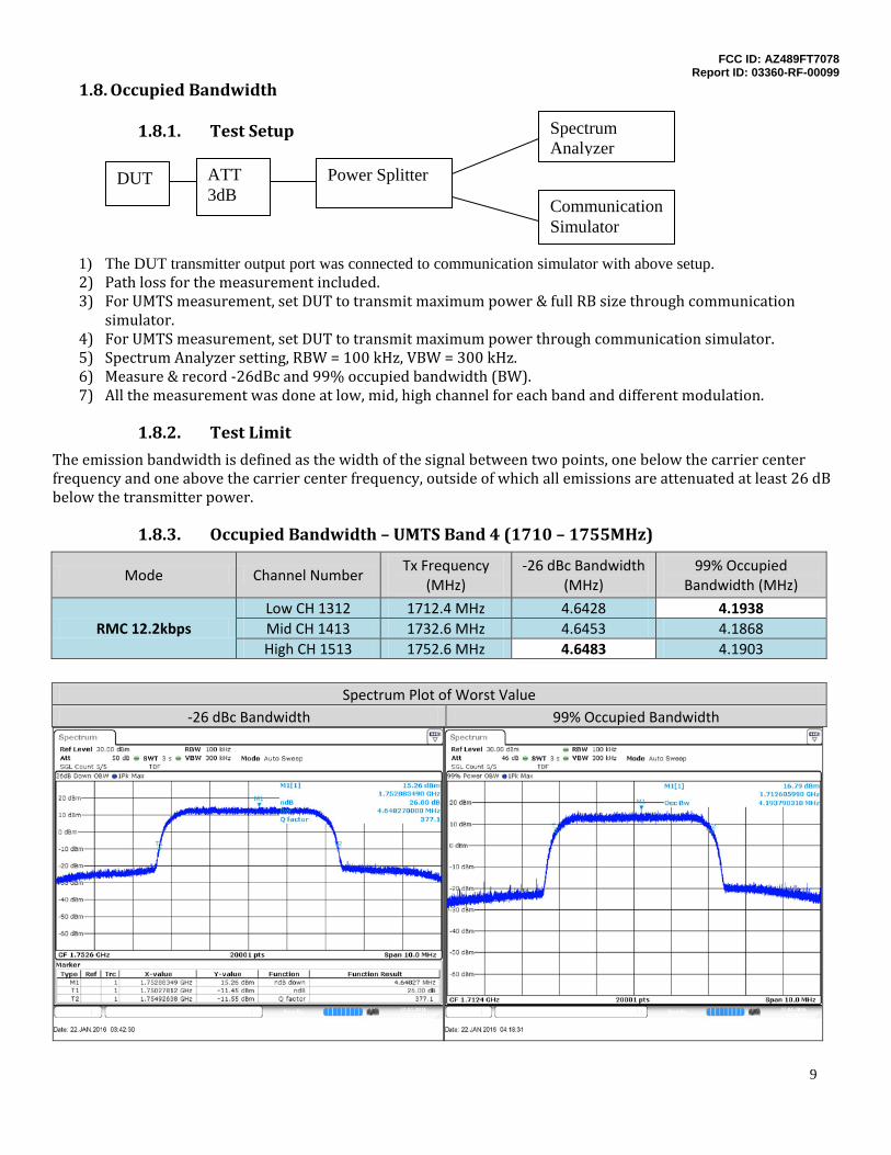
1.8. Occupied Bandwidth
1.8.1. Test Setup
1) The DUT transmitter output port was connected to communication simulator with above setup. 2) Path loss for the measurement included. 3) For UMTS measurement, set DUT to transmit maximum power & full RB size through communication
simulator. 4) For UMTS measurement, set DUT to transmit maximum power through communication simulator. 5) Spectrum Analyzer setting, RBW = 100 kHz, VBW = 300 kHz. 6) Measure & record -26dBc and 99% occupied bandwidth (BW). 7) All the measurement was done at low, mid, high channel for each band and different modulation.
1.8.2. Test Limit
The emission bandwidth is defined as the width of the signal between two points, one below the carrier center frequency and one above the carrier center frequency, outside of which all emissions are attenuated at least 26 dB below the transmitter power.
1.8.3. Occupied Bandwidth – UMTS Band 4 (1710 – 1755MHz)
Mode Channel Number Tx Frequency
(MHz) -26 dBc Bandwidth
(MHz) 99% Occupied
Bandwidth (MHz)
RMC 12.2kbps Low CH 1312 1712.4 MHz 4.6428 4.1938 Mid CH 1413 1732.6 MHz 4.6453 4.1868 High CH 1513 1752.6 MHz 4.6483 4.1903
Spectrum Plot of Worst Value
-26 dBc Bandwidth 99% Occupied Bandwidth
Communication Simulator
Spectrum Analyzer
DUT Power Splitter ATT 3dB
FCC ID: AZ489FT7078 Report ID: 03360-RF-00099
10
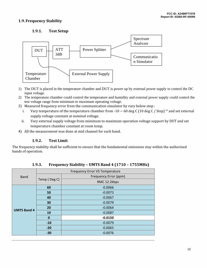
1.9. Frequency Stability
1.9.1. Test Setup
1) The DUT is placed in the temperature chamber and DUT is power up by external power supply to control the DC input voltage.
2) The temperature chamber could control the temperature and humidity and external power supply could control the test voltage range from minimum to maximum operating voltage.
3) Measured frequency error from the communication simulator by vary below step : i. Vary temperature of the temperature chamber from -10 ~ 60 deg C (10 deg C / Step) ** and set external
supply voltage constant at nominal voltage. ii. Vary external supply voltage from minimum to maximum operation voltage support by DUT and set
temperature chamber constant at room temp. 4) All the measurement was done at mid channel for each band.
1.9.2. Test Limit
The frequency stability shall be sufficient to ensure that the fundamental emissions stay within the authorized bands of operation.
1.9.3. Frequency Stability – UMTS Band 4 (1710 – 1755MHz)
Band
Frequency Error VS Temperature
Temp ( Deg C) Frequency Error (ppm)
RMC 12.2kbps
UMTS Band 4
60 -0.0066 50 -0.0073 40 -0.0067 30 -0.0079 20 -0.0064 10 -0.0087 0 -0.0150
-10 -0.0079 -20 -0.0065 -30 -0.0076
Communication Simulator
Spectrum Analyzer
DUT Power Splitter ATT 3dB
External Power Supply
Temperature Chamber
FCC ID: AZ489FT7078 Report ID: 03360-RF-00099
11
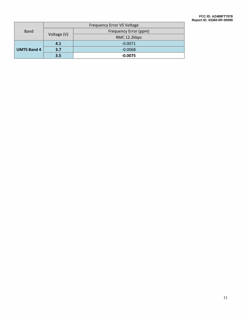
Band Frequency Error VS Voltage
Voltage (V) Frequency Error (ppm)
RMC 12.2kbps
UMTS Band 4 4.1 -0.0071 3.7 -0.0068 3.5 -0.0075
FCC ID: AZ489FT7078 Report ID: 03360-RF-00099
12
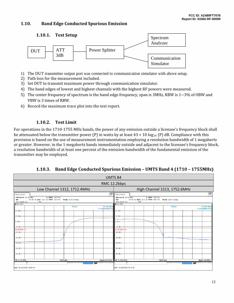
1.10. Band Edge Conducted Spurious Emission
1.10.1. Test Setup
1) The DUT transmitter output port was connected to communication simulator with above setup. 2) Path loss for the measurement included. 3) Set DUT to transmit maximum power through communication simulator. 4) The band edges of lowest and highest channels with the highest RF powers were measured. 5) The center frequency of spectrum is the band edge frequency, span is 3MHz, RBW is 1~3% of OBW and
VBW is 3 times of RBW. 6) Record the maximum trace plot into the test report.
1.10.2. Test Limit
For operations in the 1710-1755 MHz bands, the power of any emission outside a licensee's frequency block shall be attenuated below the transmitter power (P) in watts by at least 43 + 10 log10 (P) dB. Compliance with this provision is based on the use of measurement instrumentation employing a resolution bandwidth of 1 megahertz or greater. However, in the 1 megahertz bands immediately outside and adjacent to the licensee's frequency block, a resolution bandwidth of at least one percent of the emission bandwidth of the fundamental emission of the transmitter may be employed.
1.10.3. Band Edge Conducted Spurious Emission – UMTS Band 4 (1710 – 1755MHz)
UMTS B4
RMC 12.2kbps Low Channel 1312, 1712.4MHz High Channel 1513, 1752.6MHz
Communication Simulator
Spectrum Analyzer
DUT Power Splitter ATT 3dB
FCC ID: AZ489FT7078 Report ID: 03360-RF-00099
13
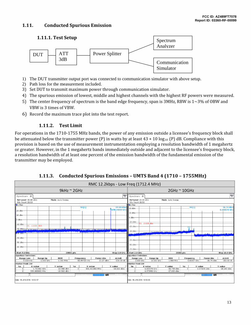
1.11. Conducted Spurious Emission
1.11.1. Test Setup
1) The DUT transmitter output port was connected to communication simulator with above setup. 2) Path loss for the measurement included. 3) Set DUT to transmit maximum power through communication simulator. 4) The spurious emission of lowest, middle and highest channels with the highest RF powers were measured. 5) The center frequency of spectrum is the band edge frequency, span is 3MHz, RBW is 1~3% of OBW and
VBW is 3 times of VBW. 6) Record the maximum trace plot into the test report.
1.11.2. Test Limit
For operations in the 1710-1755 MHz bands, the power of any emission outside a licensee's frequency block shall be attenuated below the transmitter power (P) in watts by at least 43 + 10 log10 (P) dB. Compliance with this provision is based on the use of measurement instrumentation employing a resolution bandwidth of 1 megahertz or greater. However, in the 1 megahertz bands immediately outside and adjacent to the licensee's frequency block, a resolution bandwidth of at least one percent of the emission bandwidth of the fundamental emission of the transmitter may be employed.
1.11.3. Conducted Spurious Emissions – UMTS Band 4 (1710 – 1755MHz)
RMC 12.2kbps - Low Freq (1712.4 MHz) 9kHz ~ 2GHz 2GHz ~ 10GHz
Communication Simulator
Spectrum Analyzer
DUT Power Splitter ATT 3dB
FCC ID: AZ489FT7078 Report ID: 03360-RF-00099
14
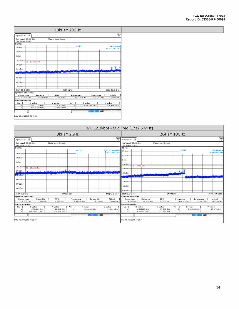
10kHz ~ 20GHz
RMC 12.2kbps - Mid Freq (1732.6 MHz) 9kHz ~ 2GHz 2GHz ~ 10GHz
FCC ID: AZ489FT7078 Report ID: 03360-RF-00099
15
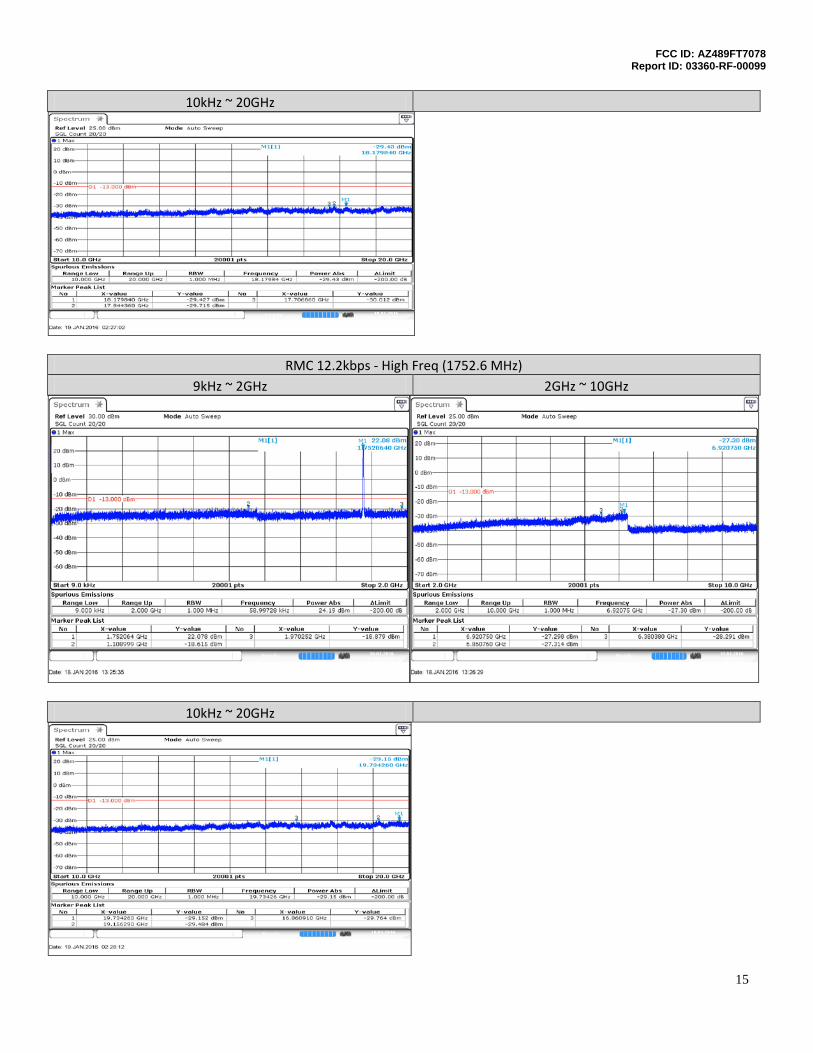
10kHz ~ 20GHz
RMC 12.2kbps - High Freq (1752.6 MHz) 9kHz ~ 2GHz 2GHz ~ 10GHz
10kHz ~ 20GHz
FCC ID: AZ489FT7078 Report ID: 03360-RF-00099
16
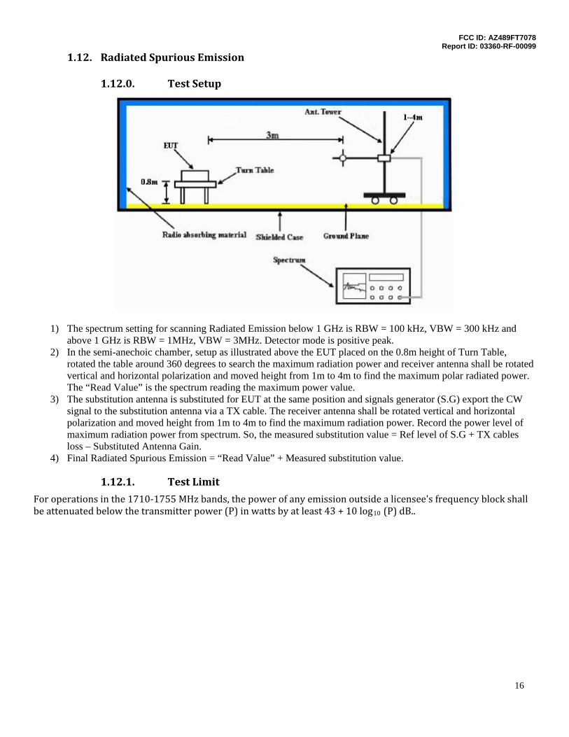
1.12. Radiated Spurious Emission
1.12.0. Test Setup
1) The spectrum setting for scanning Radiated Emission below 1 GHz is RBW = 100 kHz, VBW = 300 kHz and above 1 GHz is RBW = 1MHz, VBW = 3MHz. Detector mode is positive peak.
2) In the semi-anechoic chamber, setup as illustrated above the EUT placed on the 0.8m height of Turn Table, rotated the table around 360 degrees to search the maximum radiation power and receiver antenna shall be rotated vertical and horizontal polarization and moved height from 1m to 4m to find the maximum polar radiated power. The “Read Value” is the spectrum reading the maximum power value.
3) The substitution antenna is substituted for EUT at the same position and signals generator (S.G) export the CW signal to the substitution antenna via a TX cable. The receiver antenna shall be rotated vertical and horizontal polarization and moved height from 1m to 4m to find the maximum radiation power. Record the power level of maximum radiation power from spectrum. So, the measured substitution value = Ref level of S.G + TX cables loss – Substituted Antenna Gain.
4) Final Radiated Spurious Emission = “Read Value” + Measured substitution value.
1.12.1. Test Limit
For operations in the 1710-1755 MHz bands, the power of any emission outside a licensee's frequency block shall be attenuated below the transmitter power (P) in watts by at least 43 + 10 log10 (P) dB..
FCC ID: AZ489FT7078 Report ID: 03360-RF-00099
17
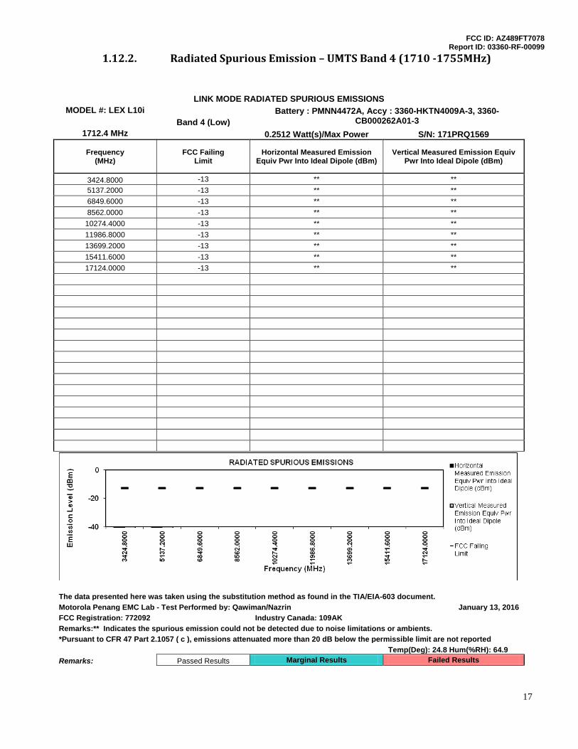
1.12.2. Radiated Spurious Emission – UMTS Band 4 (1710 -1755MHz)
LINK MODE RADIATED SPURIOUS EMISSIONS MODEL #: LEX L10i Battery : PMNN4472A, Accy : 3360-HKTN4009A-3, 3360-
CB000262A01-3 Band 4 (Low)
1712.4 MHz
0.2512 Watt(s)/Max Power S/N: 171PRQ1569
Frequency
(MHz) FCC Failing
Limit Horizontal Measured Emission
Equiv Pwr Into Ideal Dipole (dBm) Vertical Measured Emission Equiv
Pwr Into Ideal Dipole (dBm)
3424.8000 -13 ** **
5137.2000 -13 ** **
6849.6000 -13 ** **
8562.0000 -13 ** **
10274.4000 -13 ** **
11986.8000 -13 ** **
13699.2000 -13 ** **
15411.6000 -13 ** **
17124.0000 -13 ** **
The data presented here was taken using the substitution method as found in the TIA/EIA-603 document.
Motorola Penang EMC Lab - Test Performed by: Qawiman/Nazrin January 13, 2016
FCC Registration: 772092 Industry Canada: 109AK
Remarks:** Indicates the spurious emission could not be detected due to noise limitations or ambients.
*Pursuant to CFR 47 Part 2.1057 ( c ), emissions attenuated more than 20 dB below the permissible limit are not reported
Temp(Deg): 24.8 Hum(%RH): 64.9
Remarks: Passed Results Marginal Results Failed Results
FCC ID: AZ489FT7078 Report ID: 03360-RF-00099
18
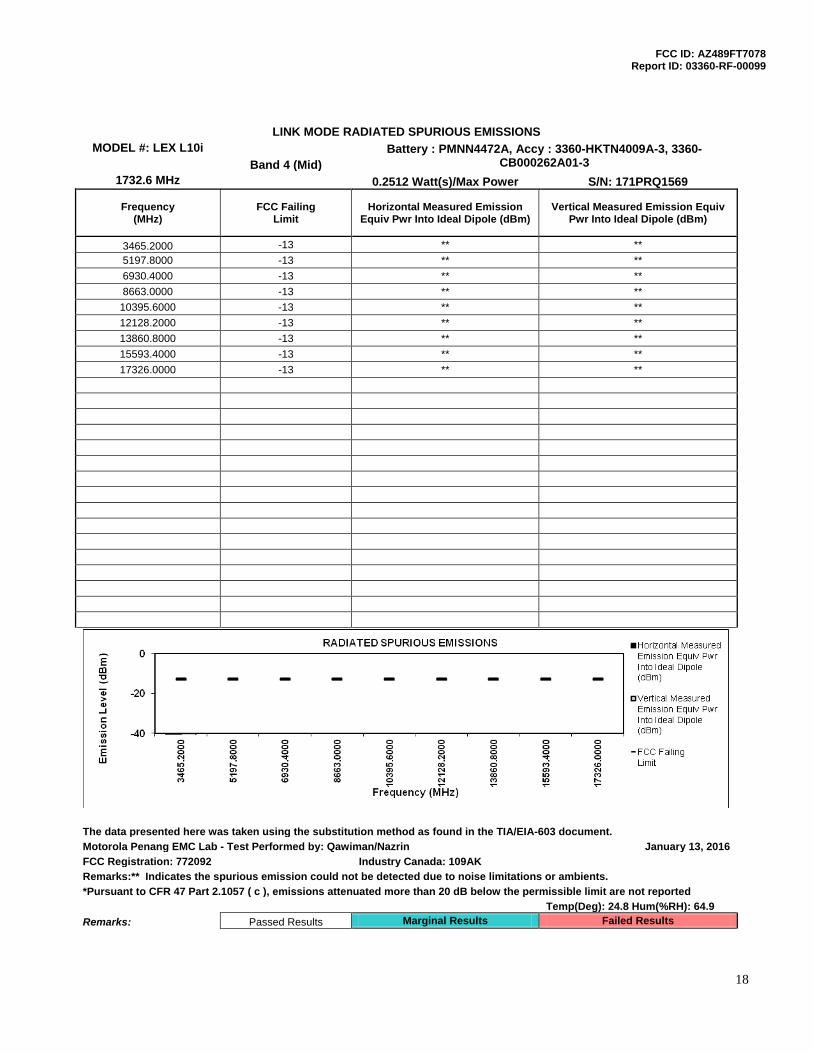
LINK MODE RADIATED SPURIOUS EMISSIONS MODEL #: LEX L10i Battery : PMNN4472A, Accy : 3360-HKTN4009A-3, 3360-
CB000262A01-3 Band 4 (Mid)
1732.6 MHz
0.2512 Watt(s)/Max Power S/N: 171PRQ1569
Frequency
(MHz) FCC Failing
Limit Horizontal Measured Emission
Equiv Pwr Into Ideal Dipole (dBm) Vertical Measured Emission Equiv
Pwr Into Ideal Dipole (dBm)
3465.2000 -13 ** **
5197.8000 -13 ** **
6930.4000 -13 ** **
8663.0000 -13 ** **
10395.6000 -13 ** **
12128.2000 -13 ** **
13860.8000 -13 ** **
15593.4000 -13 ** **
17326.0000 -13 ** **
* Indicates the spurious emission could not be detected due to noise limitations or ambients.
The data presented was taken using the substitution method as found in the TIA/EIA-603 document.
The data presented here was taken using the substitution method as found in the TIA/EIA-603 document.
Motorola Penang EMC Lab - Test Performed by: Qawiman/Nazrin January 13, 2016
FCC Registration: 772092 Industry Canada: 109AK
Remarks:** Indicates the spurious emission could not be detected due to noise limitations or ambients.
*Pursuant to CFR 47 Part 2.1057 ( c ), emissions attenuated more than 20 dB below the permissible limit are not reported
Temp(Deg): 24.8 Hum(%RH): 64.9
Remarks: Passed Results Marginal Results Failed Results
FCC ID: AZ489FT7078 Report ID: 03360-RF-00099
19
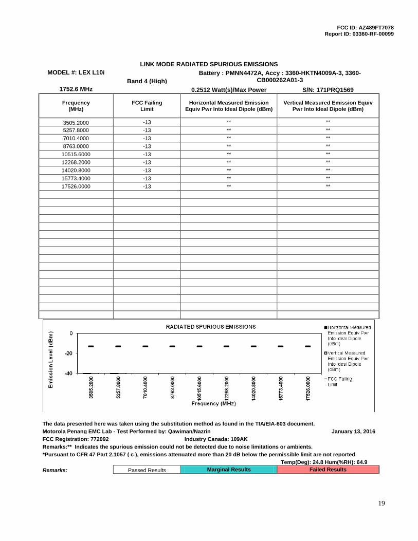
LINK MODE RADIATED SPURIOUS EMISSIONS MODEL #: LEX L10i Battery : PMNN4472A, Accy : 3360-HKTN4009A-3, 3360-
CB000262A01-3 Band 4 (High)
1752.6 MHz
0.2512 Watt(s)/Max Power S/N: 171PRQ1569
Frequency
(MHz) FCC Failing
Limit Horizontal Measured Emission
Equiv Pwr Into Ideal Dipole (dBm) Vertical Measured Emission Equiv
Pwr Into Ideal Dipole (dBm)
3505.2000 -13 ** **
5257.8000 -13 ** **
7010.4000 -13 ** **
8763.0000 -13 ** **
10515.6000 -13 ** **
12268.2000 -13 ** **
14020.8000 -13 ** **
15773.4000 -13 ** **
17526.0000 -13 ** **
The data presented here was taken using the substitution method as found in the TIA/EIA-603 document.
Motorola Penang EMC Lab - Test Performed by: Qawiman/Nazrin January 13, 2016
FCC Registration: 772092 Industry Canada: 109AK
Remarks:** Indicates the spurious emission could not be detected due to noise limitations or ambients.
*Pursuant to CFR 47 Part 2.1057 ( c ), emissions attenuated more than 20 dB below the permissible limit are not reported
Temp(Deg): 24.8 Hum(%RH): 64.9
Remarks: Passed Results Marginal Results Failed Results
FCC ID: AZ489FT7078 Report ID: 03360-RF-00099
20
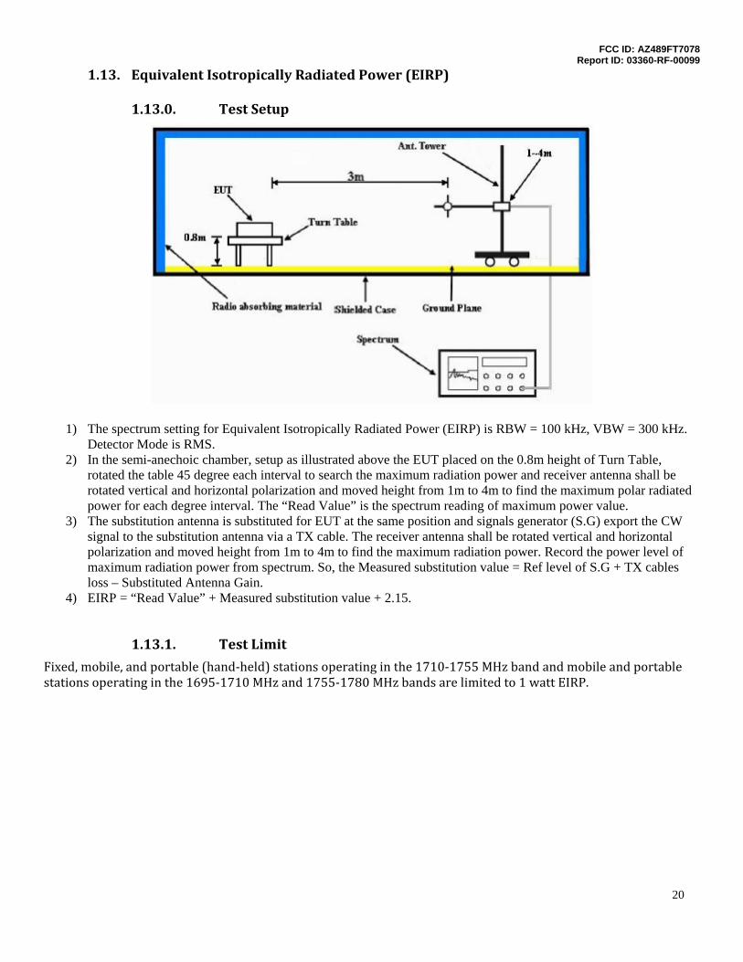
1.13. Equivalent Isotropically Radiated Power (EIRP)
1.13.0. Test Setup
1) The spectrum setting for Equivalent Isotropically Radiated Power (EIRP) is RBW = 100 kHz, VBW = 300 kHz. Detector Mode is RMS.
2) In the semi-anechoic chamber, setup as illustrated above the EUT placed on the 0.8m height of Turn Table, rotated the table 45 degree each interval to search the maximum radiation power and receiver antenna shall be rotated vertical and horizontal polarization and moved height from 1m to 4m to find the maximum polar radiated power for each degree interval. The “Read Value” is the spectrum reading of maximum power value.
3) The substitution antenna is substituted for EUT at the same position and signals generator (S.G) export the CW signal to the substitution antenna via a TX cable. The receiver antenna shall be rotated vertical and horizontal polarization and moved height from 1m to 4m to find the maximum radiation power. Record the power level of maximum radiation power from spectrum. So, the Measured substitution value = Ref level of S.G + TX cables loss – Substituted Antenna Gain.
4) EIRP = “Read Value” + Measured substitution value + 2.15.
1.13.1. Test Limit
Fixed, mobile, and portable (hand-held) stations operating in the 1710-1755 MHz band and mobile and portable stations operating in the 1695-1710 MHz and 1755-1780 MHz bands are limited to 1 watt EIRP.
FCC ID: AZ489FT7078 Report ID: 03360-RF-00099
21
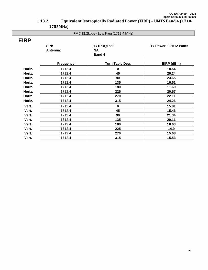
1.13.2. Equivalent Isotropically Radiated Power (EIRP) – UMTS Band 4 (1710-1755MHz)
RMC 12.2kbps - Low Freq (1712.4 MHz)
EIRP
S/N: 171PRQ1568 Tx Power: 0.2512 Watts
Antenna: NA
Band 4
Frequency Turn Table Deg. EIRP (dBm)
Horiz. 1712.4 0 18.54 Horiz. 1712.4 45 26.24 Horiz. 1712.4 90 23.65 Horiz. 1712.4 135 16.51 Horiz. 1712.4 180 11.69 Horiz. 1712.4 225 20.57 Horiz. 1712.4 270 22.11 Horiz. 1712.4 315 24.26 Vert. 1712.4 0 15.81 Vert. 1712.4 45 15.46 Vert. 1712.4 90 21.34 Vert. 1712.4 135 20.11 Vert. 1712.4 180 18.63 Vert. 1712.4 225 14.9 Vert. 1712.4 270 15.68 Vert. 1712.4 315 15.53
FCC ID: AZ489FT7078 Report ID: 03360-RF-00099
22
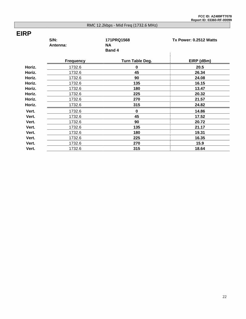
RMC 12.2kbps - Mid Freq (1732.6 MHz)
EIRP
S/N: 171PRQ1568 Tx Power: 0.2512 Watts
Antenna: NA
Band 4
Frequency Turn Table Deg. EIRP (dBm)
Horiz. 1732.6 0 20.5 Horiz. 1732.6 45 26.34 Horiz. 1732.6 90 24.08 Horiz. 1732.6 135 16.15 Horiz. 1732.6 180 13.47 Horiz. 1732.6 225 20.32 Horiz. 1732.6 270 21.57 Horiz. 1732.6 315 24.82 Vert. 1732.6 0 14.86 Vert. 1732.6 45 17.52 Vert. 1732.6 90 20.72 Vert. 1732.6 135 21.17 Vert. 1732.6 180 19.31 Vert. 1732.6 225 16.35 Vert. 1732.6 270 15.9 Vert. 1732.6 315 18.64
FCC ID: AZ489FT7078 Report ID: 03360-RF-00099
23
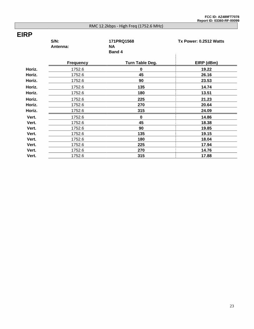
RMC 12.2kbps - High Freq (1752.6 MHz)
EIRP
S/N: 171PRQ1568 Tx Power: 0.2512 Watts
Antenna: NA
Band 4
Frequency Turn Table Deg. EIRP (dBm)
Horiz. 1752.6 0 19.22 Horiz. 1752.6 45 26.16 Horiz. 1752.6 90 23.53 Horiz. 1752.6 135 14.74 Horiz. 1752.6 180 13.51 Horiz. 1752.6 225 21.23 Horiz. 1752.6 270 20.64 Horiz. 1752.6 315 24.09 Vert. 1752.6 0 14.86 Vert. 1752.6 45 18.38 Vert. 1752.6 90 19.85 Vert. 1752.6 135 19.15 Vert. 1752.6 180 18.04 Vert. 1752.6 225 17.94 Vert. 1752.6 270 14.76 Vert. 1752.6 315 17.88