
PARALLEL CONNECTED INVERTER FORFUEL CELL...
5
2008 5th International Multi-Conference on Systems, Signals and Devices PARALLEL CONNECTED INVERTER FOR FUEL CELL SYSTEM MA.A. Younis 1 , N A. Rahim 2 and S. Mekhilej3 1EE Dept., unisel, selangor, malaysia 2,3EE dept. urn, 50603, kuala lumpur,malaysia. E-Mail: [email protected] ABSTRACT This paper presents the design and analysis of a new configuration of parallel connected inverter suitable for fuel cell system application. The configuration consists of dc/dc converter and parallel three-phase dc/ac inverter. Series resistors added to the inverter output to maintain same current in each inverter of the two parallel inverters, and to reduce the circulating current in the parallel inverters to minimum. Third harmonic injection PWM (TmpWM) reduces the total harmonic distortion and to make maximum use of the voltage source. DSP was used to create the TmpWM and the control algorithm for the converter. PID controller is applied on the full-bridge dc/dc converter side to maintain the ac voltage to the required level. Experimental results have been shown to validate the proposed system. Index Terms- three-phase inverter, Third harmonic injection PWM, inverters parallel connection, fuel cell system. 1. INTRODUCTION In recent years, many concerns have been raised over the fossil fuel-electricity generation, since it pollutes our environment and depletes the energy supply [1]. Alternative energy sources, such as fuel cells, gain a lot of attention because it is friendly to the environment and flexible for installation. Fuel cells are currently considered attractive power sources for portable power applications in civilian arenas because of their superior power densities, silent operation and non-polluting nature [2].However, this type of sources provides unstable dc voltage which needs to be stabilized and converted to ac voltage to be suitable for ac load application .. With PWM control technologies, ac side of the grid connected inverter has the abilities of controllable power factor, sinusoidal output currents and bi-directional power transfer. [3][4] The third harmonic injection method to control the power factor of the inverter output current used for three-phase inverter. However, it is very difficult to generate the right third harmonic amplitude [5] [6]. In hysteresis control the s\vitching frequency varies significantly according to the power level and the dc link [7] [8]. 978-1-4244-2206-7/08/$25.00 ©2008 IEEE The fuel cells system typically consists of a dc/dc converter to boost the source voltage to a higher level and a dc/ac inverter. Several variations of this scheme have been proposed in the literature [9] [10], each presenting advantages and disadvantages. Isolated dc/dc converter became a hot topic in the last decade because of their wide application in green power application which includes solar, wind, geothermal, ocean energy and fuel cell. The front end of the isolated dc-dc converter, which is full bridges have been seen in most applications. Compared with half bridge, full bridge will have less current stress and doubled input voltage utilization. 2. SYSTEM BLOCK DIAGRAM The block diagram of the system is shown in Figure 1. The dc voltage produced by the dc power supply is converted to a high-frequency train of positive and negative pulse pairs by the full-bridge converter, which is controlled by the phase-shift modulation technique. The widths of the positive and negative pulses in each pair are equal in attempt to avoid saturation of the high-frequency transformer. The high-frequency transformer isolates the dc source from the grid and steps up the amplitudes of the pulses to the level required for the successful control of grid voltage. As the local average of the pulse train on the secondary-side of the transformer is zero, rectification through the diode-rectifier bridge is used to produce a train of positive pulses of nonzero local average. The rectified voltage ripple reduces to minimum value using high capacitor value. The Six-step modulation uses a sequence of six switches patterns for three-phase full- bridge inverter to generate a full cycle of three-phase voltages. 3. ISOLATED DC/DC CONVERTER The isolated dc/dc converter shown in Figure 2 consist of two stages where the dc power converted to a high- frequency train of positive and negative pulse pairs by inverter stage. The produced voltage stepped up using high frequency transformer followed by full bridge rectifier. The high frequency transformer employed to realize isolation between the dc source and the grid, and to get high dc voltage on the converter output.
Transcript of PARALLEL CONNECTED INVERTER FORFUEL CELL...
2008 5th International Multi-Conference on Systems, Signals and Devices
PARALLEL CONNECTED INVERTER FOR FUEL CELL SYSTEM
MA.A. Younis 1, N A. Rahim2 and S. Mekhilej3
1EE Dept., unisel, selangor, malaysia2,3EE dept. urn, 50603, kuala lumpur,malaysia.
E-Mail: [email protected]
ABSTRACT
This paper presents the design and analysis of a newconfiguration of parallel connected inverter suitable forfuel cell system application. The configuration consists ofdc/dc converter and parallel three-phase dc/ac inverter.Series resistors added to the inverter output to maintainsame current in each inverter of the two parallel inverters,and to reduce the circulating current in the parallelinverters to minimum. Third harmonic injection PWM(TmpWM) reduces the total harmonic distortion and tomake maximum use of the voltage source. DSP was usedto create the TmpWM and the control algorithm for theconverter. PID controller is applied on the full-bridgedc/dc converter side to maintain the ac voltage to therequired level. Experimental results have been shown tovalidate the proposed system.
Index Terms- three-phase inverter, Third harmonicinjection PWM, inverters parallel connection, fuel cellsystem.
1. INTRODUCTION
In recent years, many concerns have been raised over thefossil fuel-electricity generation, since it pollutes ourenvironment and depletes the energy supply [1].Alternative energy sources, such as fuel cells, gain a lotof attention because it is friendly to the environment andflexible for installation. Fuel cells are currentlyconsidered attractive power sources for portable powerapplications in civilian arenas because of their superiorpower densities, silent operation and non-polluting nature[2].However, this type of sources provides unstable dcvoltage which needs to be stabilized and converted to acvoltage to be suitable for ac load application.. With PWMcontrol technologies, ac side of the grid connectedinverter has the abilities of controllable power factor,sinusoidal output currents and bi-directional powertransfer. [3][4] The third harmonic injection method tocontrol the power factor of the inverter output currentused for three-phase inverter. However, it is very difficultto generate the right third harmonic amplitude [5] [6]. Inhysteresis control the s\vitching frequency variessignificantly according to the power level and the dc link[7] [8].
978-1-4244-2206-7/08/$25.00 ©2008 IEEE
The fuel cells system typically consists of a dc/dcconverter to boost the source voltage to a higher level anda dc/ac inverter. Several variations of this scheme havebeen proposed in the literature [9] [10], each presentingadvantages and disadvantages. Isolated dc/dc converterbecame a hot topic in the last decade because of theirwide application in green power application whichincludes solar, wind, geothermal, ocean energy and fuelcell. The front end of the isolated dc-dc converter, whichis full bridges have been seen in most applications.Compared with half bridge, full bridge will have lesscurrent stress and doubled input voltage utilization.
2. SYSTEM BLOCK DIAGRAM
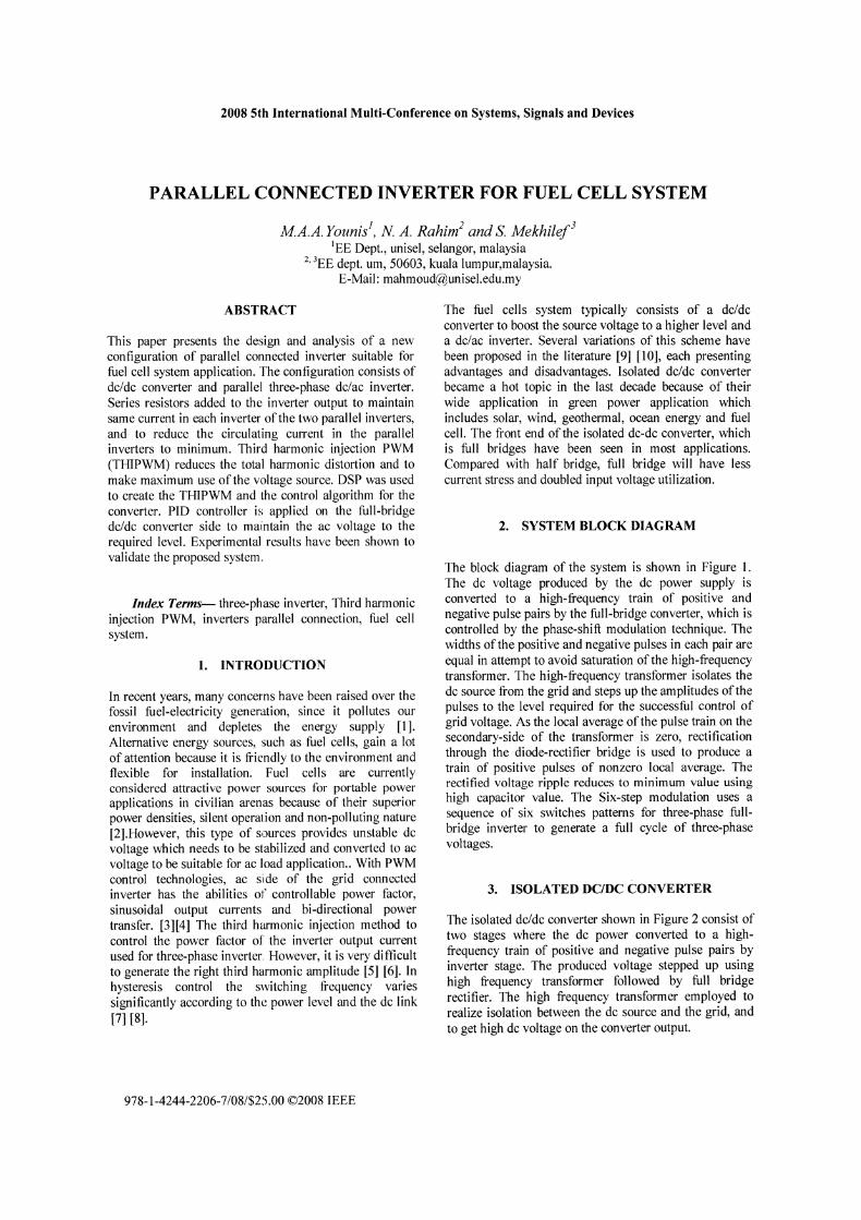
The block diagram of the system is shown in Figure 1.The dc voltage produced by the dc power supply isconverted to a high-frequency train of positive andnegative pulse pairs by the full-bridge converter, which iscontrolled by the phase-shift modulation technique. Thewidths of the positive and negative pulses in each pair areequal in attempt to avoid saturation of the high-frequencytransformer. The high-frequency transformer isolates thedc source from the grid and steps up the amplitudes of thepulses to the level required for the successful control ofgrid voltage. As the local average of the pulse train on thesecondary-side of the transformer is zero, rectificationthrough the diode-rectifier bridge is used to produce atrain of positive pulses of nonzero local average. Therectified voltage ripple reduces to minimum value usinghigh capacitor value. The Six-step modulation uses asequence of six switches patterns for three-phase fullbridge inverter to generate a full cycle of three-phasevoltages.
3. ISOLATED DC/DC CONVERTER
The isolated dc/dc converter shown in Figure 2 consist oftwo stages where the dc power converted to a highfrequency train of positive and negative pulse pairs byinverter stage. The produced voltage stepped up usinghigh frequency transformer followed by full bridgerectifier. The high frequency transformer employed torealize isolation between the dc source and the grid, andto get high dc voltage on the converter output.
2008 5th International Multi-Conference on Systems, Signals and Devices
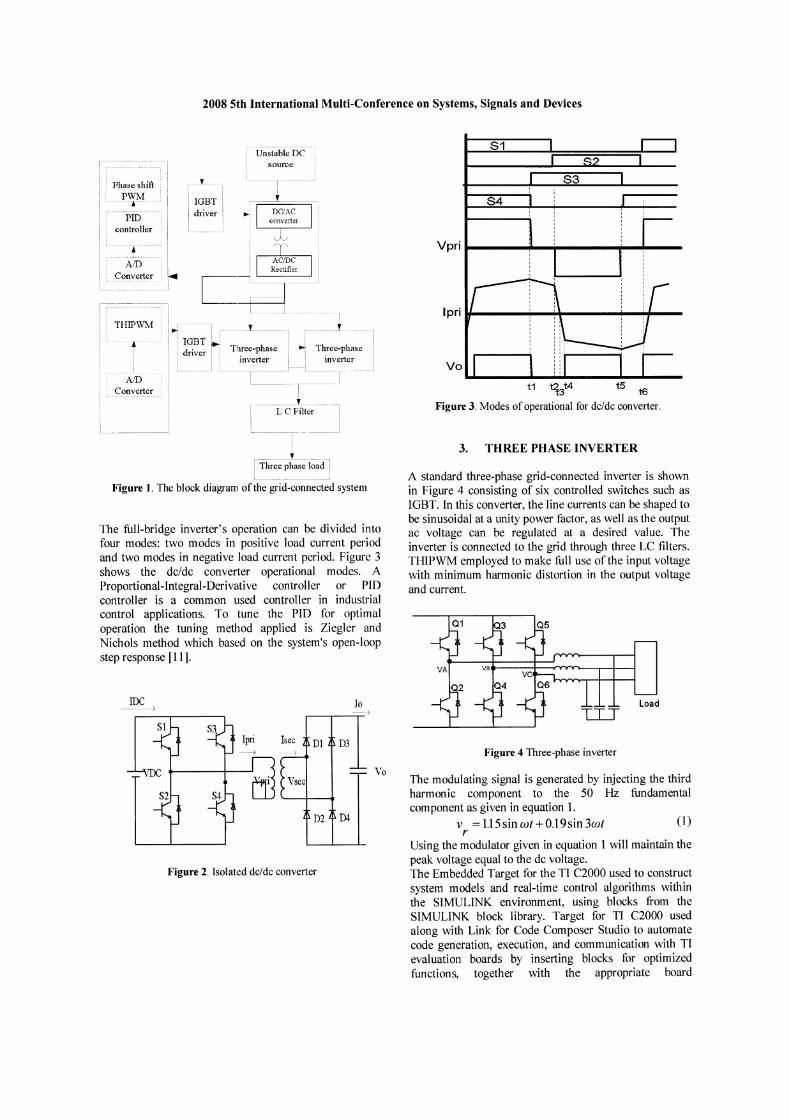
The full-bridge inverter's operation can be divided intofour modes: two modes in positive load current periodand two modes in negative load current period. Figure 3shows the dc/dc converter operational modes. AProportional-Integral-Derivative controller or PIDcontroller is a common used controller in industrialcontrol applications. To tune the PID for optimaloperation the tuning method applied is Ziegler andNichols method which based on the system's open-loopstep response [11].
Load
Figure 4 Three-phase inverter
3. THREE PHASE INVERTER
Vo
Vpri .... ..._ .... ...._~__
Ipri .... ~-......----...........-_
t1 "ti3t4 t5 t6
Figure 3. Modes of operational for dcldc converter.
The modulating signal is generated by injecting the thirdharmonic component to the 50 Hz fundamentalcomponent as given in equation 1.
v = 1.15 sin wt +O.l9sin 3wt (1)r
Using the modulator given in equation 1 will maintain thepeak voltage equal to the dc voltage.The Embedded Target for the TI C2000 used to constructsystem models and real-time control algorithms withinthe SIMULINK environment, using blocks from theSIMULINK block library. Target for TI C2000 usedalong with Link for Code Composer Studio to automatecode generation, execution, and communication with TIevaluation boards by inserting blocks for optimizedfunctions, together with the appropriate board
A standard three-phase grid-connected inverter is shownin Figure 4 consisting of six controlled switches such asIGBT. In this converter, the line currents can be shaped tobe sinusoidal at a unity power factor, as well as the outputac voltage can be regulated at a desired value. Theinverter is connected to the grid through three LC filters.THIPWM employed to make full use of the input voltagewith minimum harmonic distortion in the output voltageand current.
Vo
10~
I-lli-~t~ble DC- 1
I source I
_ J-T .-~--l
IGBT I
~:
Figure 2. Isolated dcldc converter
IDC-------j
Converter
~I: c;~:;;r~
ACJDCRectIfier IC -- J
-13_ ___t
~~~n T~~;~~;se -II~~~~~~;se------ L T---------1
----~----- ---.l. L C Filter I
-----T-
~--~hree~as~adJ
Figure 1. The block diagram of the grid-connected system
lu;h~S~Shift Ii J>~~L---:
PIDcontroller
2008 5th International Multi-Conference on Systems, Signals and Devices
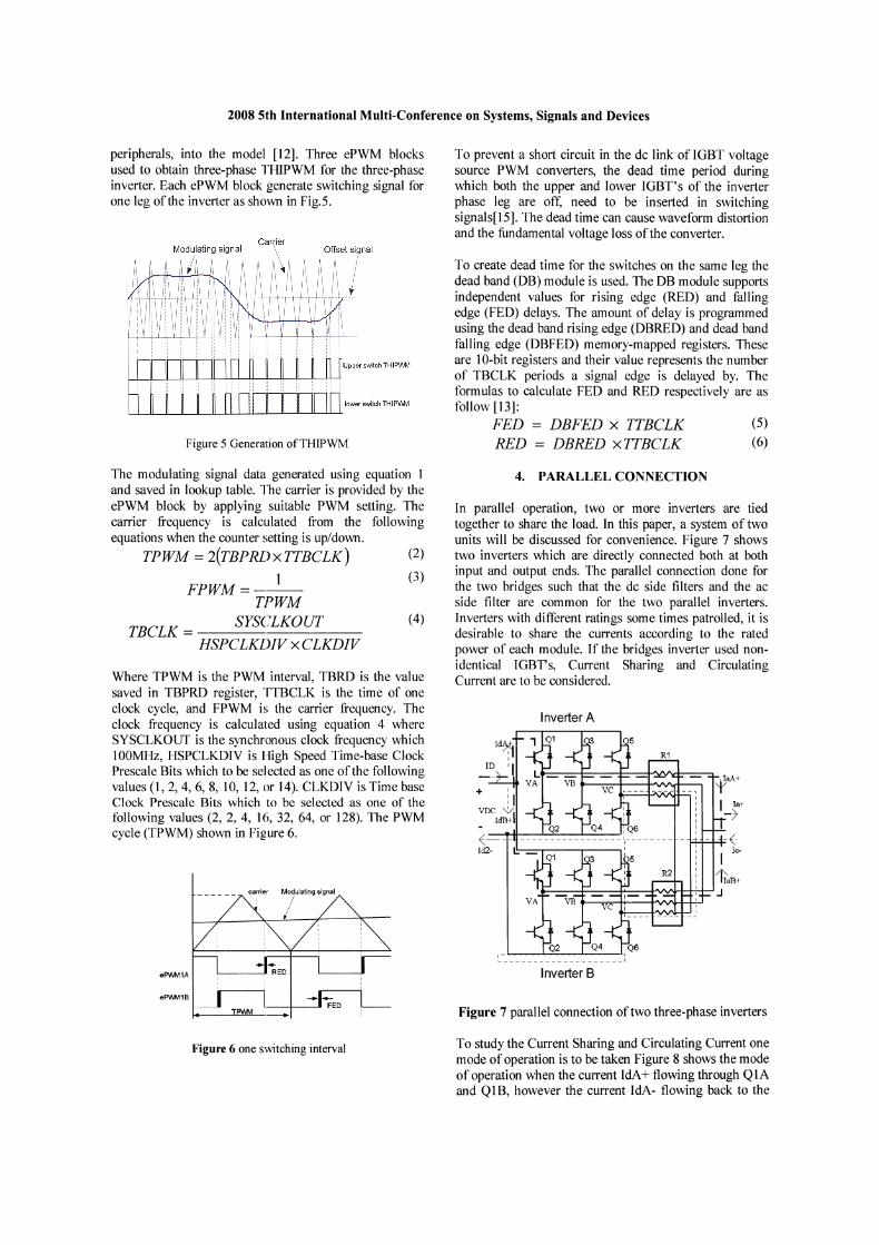
peripherals, into the model [12]. Three ePWM blocksused to obtain three-phase THIPWM for the three-phaseinverter. Each ePWM block generate switching signal forone leg of the inverter as shown in Fig.5.
Offset jgnal
Upper switch THIPV\IM
lower switch TI-li PV\M
Figure 5 Generation ofTHIPWM
To prevent a short circuit in the dc link of IGBT voltagesource PWM converters, the dead time period duringwhich both the upper and lower IGBT's of the inverterphase leg are off, need to be inserted in switchingsignals[15]. The dead time can cause waveform distortionand the fundamental voltage loss of the converter.
To create dead time for the switches on the same leg thedead band (DB) module is used. The DB module supportsindependent values for rising edge (RED) and fallingedge (FED) delays. The amount of delay is programmedusing the dead band rising edge (DBRED) and dead bandfalling edge (DBFED) memory-mapped registers. Theseare la-bit registers and their value represents the numberof TBCLK periods a signal edge is delayed by. Theformulas to calculate FED and RED respectively are asfollow [13]:
FED = DBFED X TTBCLK (5)
RED = DBRED xTTBCLK (6)
carrier Modulating signal
Where TPWM is the PWM interval, TBRD is the valuesaved in TBPRD register, TTBCLK is the time of oneclock cycle, and FPWM is the carrier frequency. Theclock frequency is calculated using equation 4 whereSYSCLKOUT is the synchronous clock frequency which100MHz, HSPCLKDIV is I-ligh Speed Time-base ClockPrescale Bits which to be se] ected as one of the followingvalues (1,2,4,6,8, la, 12, or 14). CLKDIV is Time baseClock Prescale Bits which to be selected as one of thefollowing values (2, 2, 4, 16, 32, 64, or 128). The PWMcycle (TPWM) shown in Figure 6.
R2
R1
Inverter B
faA+I_)a+
- -(I Ie-
1i'aB+...----+---+O--+"VV\r-t-t-i__t___'' J
~~ J
+
Inverter A
Figure 7 parallel connection of two three-phase inverters
4. PARALLEL CONNECTION
In parallel operation, two or more inverters are tiedtogether to share the load. In this paper, a system of twounits will be discussed for convenience. Figure 7 showstwo inverters which are directly connected both at bothinput and output ends. The parallel connection done forthe two bridges such that the dc side filters and the acside filter are common for the two parallel inverters.Inverters with different ratings some times patrolled, it isdesirable to share the currents according to the ratedpower of each module. If the bridges inverter used nonidentical IGBT's, Current Sharing and CirculatingCurrent are to be considered.
(4)
(2)
(3)
: :
eP\Mv11B ~ -.Il,_-+-__TPWM ---.
eP\Mv11A
The modulating signal data generated using equation Iand saved in lookup table. The carrier is provided by theePWM block by applying suitable PWM setting. Thecarrier frequency is calculated from the followingequations when the counter setting is up/down.
TPWM = 2(TBPRl> X TTBCLK)
1FPWM=---
TPWM
TBCLK = SYS(~LKOUT
HSPCLKl>IV X CLKDIV
Figure 6 one svvitching interval To study the Current Sharing and Circulating Current onemode of operation is to be taken Figure 8 shows the modeof operation when the current IdA+ flowing through QIAand Q1B, however the current IdA- flowing back to the
2008 5th International Multi-Conference on Systems, Signals and Devices
source through Q6A and Q6b. the Figure shows thecurrent sharing between Q1A and Q1B with two seriesresistors included.
QIA
IdA+: -c~------- -~-------:;j-'----------------l\I\I\r-------,
lDVa
IdB+RllB
:_-~
Figure 8 circulating current during one switching cycle
The current sharing depends on the IGBT' s Q1A andQIB, If VCEIA not equal to VCEIB as a result IdA+will not be equal to IdB+. To maintain similar currentsharing between the two inverters series resistor RI andR2 added between each leg of the six legs and thecommon point as shown in Figure 8. RI box consists ofthree resistors RII, R12, and RI3. Similarly R2 consistsof R2I, R22, and R23. Including the resistances RIIAand RIIB as shown in Figure 8 must satisfY thefollowing condition:
VCE1A + I~ . RllA == VCE1B + I;B . R11B (7)
let. (8)
or
+ + I DIdA == I dB ==-2
I; (RllA - R iIB ) = VCEIB - VCE1A
R = 2(VCliIB - VOilA) + R11A I lIB
D
(9)
(10)
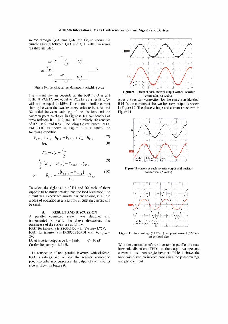
Figure 9. Current at each inverter output without resistorconnection. (2 A/div)
After the resistor connection for the same non-identicalIGBT's the currents at the two inverters output is shownin Figure 10. The phase voltage and current are shown inFigure 11
Figure 10 current at each inverter output with resistorconnection. (2 A/div)
To select the right value of RI and R2 each of themsuppose to be much smaller than the load resistance. Thecircuit will experience similar current sharing in all themodes of operation as a result the circulating current willbe small.
5. RESULT AND DISCUSSIONA parallel connected system was designed andimplemented to verifY the above discussion. Theparameters of the system are as follow.IGBT for inverter a is SSG60N60 with VCE(ON)=1.75V.IGBT for inverter b is IRGP50B60PDI with VCE (ON) =2V.LC at inverter output side L = 5 mH C= 10 J-tFCarrier frequency = 4.5 kHz
The connection of two parallel inverters with differentIGBT's ratings and without the resistor connectionproduces unbalance currents at the output of each inverterside as shown in Figure 9.
Figure 11 Phase voltage (50 V/div) and phase current (5A/div)on the load side
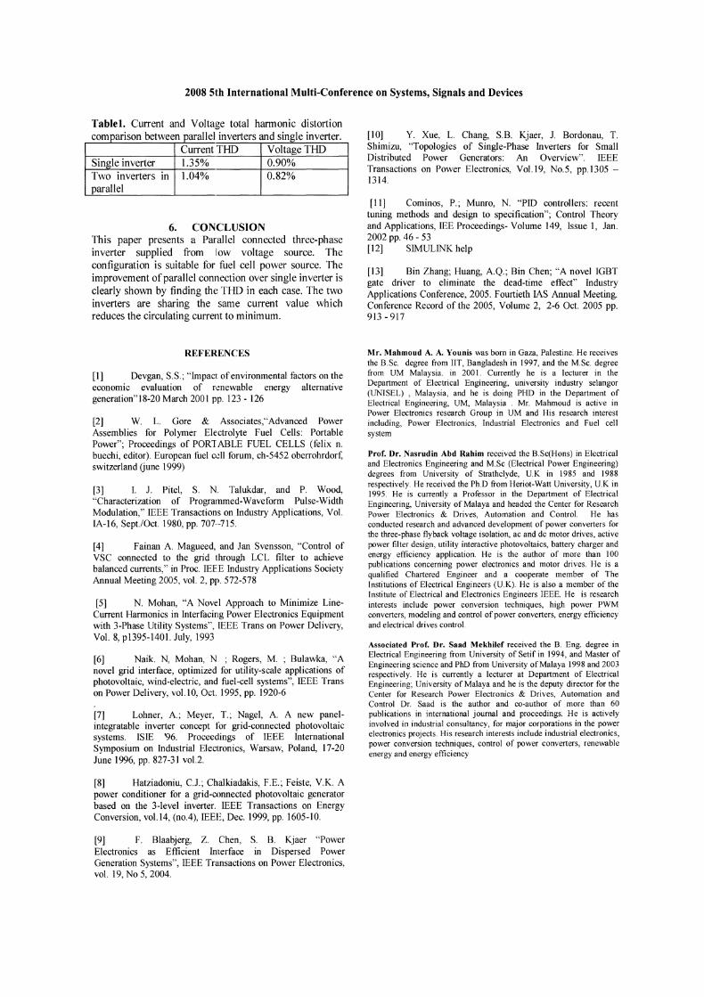
With the connection of two inverters in parallel the totalharmonic distortion (THD) on the output voltage andcurrent is less than single inverter. Table 1 shows theharmonic distortion in each case using the phase voltageand phase current.
2008 5th International Multi-Conference on Systems, Signals and Devices
Tablet. Current and Voltage total harmonic distortioncomparison between parallel inverters and single inverter.
Current THD Voltage THDSingle inverter 1.35% 0.90%Two inverters in 1.04% 0.82%parallel
6. CONCLUSIONThis paper presents a Parallel connected three-phaseinverter supplied from low voltage source. Theconfiguration is suitable for fuel cell power source. Theimprovement ofparallel connection over single inverter isclearly shown by finding the THD in each case. The twoinverters are sharing the same current value whichreduces the circulating current to minimum.
REFERENCES
[1] Devgan, S.S.~ "Impact of environmental factors on theeconomic evaluation of renewable energy alternativegeneration"18-20 March 2001 pp. 123 - 126
[2] W. L. Gore & Associates,"Advanced PowerAssemblies for Polymer Electrolyte Fuel Cells: PortablePower"~ Proceedings of PORTABLE FUEL CELLS (felix n.buechi, editor). European fuel cell forum, ch-5452 oberrohrdorf,switzerland Gune 1999)
[3] I. 1. Pitel, S. N. Talukdar, and P. Wood,"Characterization of Progratnmed-Waveform Pulse-WidthModulation," IEEE Transactions on Industry Applications, Vol.IA-16, Sept./Oct. 1980, pp. 707--715.
[4] Fainan A. Magueed, and Jan Svensson, "Control ofVSC connected to the grid through LCL filter to achievebalanced currents," in Proc. IEEE Industry Applications SocietyAnnual Meeting 2005, vol. 2, pp. 572-578
[5] N. Mohan, "A Novel Approach to Minimize Line-Current Harmonics in Interfacing Power Electronics Equipmentwith 3-Phase Utility Systems", IEEE Trans on Power Delivery,Vol. 8, p1395-1401. July, 1993
[6] Naik. N, Mohan, N. ~ Rogers, M. ; Bulawka, "Anovel grid interface, optimized for utility-scale applications ofphotovoltaic, wind-electric, and fuel-cell systems", IEEE Transon Power Delivery, vol. 10, Oct. 1995, pp. 1920-6
[7] Lohner, A.; Meyer, T.~ Nagel, A. A new panelintegratable inverter concept lor grid-connected photovoltaicsystems. ISlE '96. Proceedings of IEEE InternationalSymposium on Industrial Electronics, Warsaw, Poland, 17-20June 1996, pp. 827-31 vol.2.
[8] Hatziadoniu, C.J.~ Chalkiadakis, F.E.~ Feiste, V.K. Apower conditioner for a grid-connected photovoltaic generatorbased on the 3-level inverter. IEEE Transactions on EnergyConversion, vol. 14, (no.4), IEEE, Dec. 1999, pp. 1605-10.
[9] F. Blaabjerg, Z. Chen, S. B. Kjaer "PowerElectronics as Efficient Interface in Dispersed PowerGeneration Systems", IEEE Transactions on Power Electronics,vol. 19, No 5, 2004.
[10] Y. Xue, L. Chang, S.B. Kjaer, 1. Bordonau, T.Shimizu, "Topologies of Single-Phase Inverters for SmallDistributed Power Generators: An Overview". IEEETransactions on Power Electronics, Vol.l9, No.5, pp.1305 1314.
[11] Cominos, P. ~ Munro, N. "PID controllers: recenttuning methods and design to specification"~ Control Theoryand Applications, IEE Proceedings- Volume 149, Issue 1, Jan.2002 pp. 46 - 53[12] SIMULINK help
[13] Bin Zhang; Huang, A.Q.~ Bin Chen~ "A novel IGBTgate driver to eliminate the dead-time effect" IndustryApplications Conference, 2005. Fourtieth lAS Annual Meeting.Conference Record of the 2005, Volume 2, 2-6 Oct. 2005 pp.913-917
Mr. Mahmoud A. A. Younis was born in Gaza, Palestine. He receivesthe B.Sc. degree from lIT, Bangladesh in 1997, and the M.Sc. degreefrom UM Malaysia. in 2001. Currently he is a lecturer in theDepartment of Electrical Engineering, university industry selangor(UNISEL) , Malaysia, and he is doing PHD in the Department ofElectrical Engineering, UM, Malaysia. Mr. Mahmoud is active inPower Electronics research Group in UM and His research interestincluding, Power Electronics, Industrial Electronics and Fuel cellsystem
Prof. Dr. Nasrudin Abd Rahim received the B.Sc(Hons) in Electricaland Electronics Engineering and M.Sc (Electrical Power Engineering)degrees from University of Strathclyde, U.K in 1985 and 1988respectively. He received the Ph.D from Heriot-Watt University, U.K in1995. He is currently a Professor in the Department of ElectricalEngineering, University of Malaya and headed the Center for ResearchPower Electronics & Drives, Automation and Control. He hasconducted research and advanced development of power converters forthe three-phase flyback voltage isolation, ac and dc motor drives, activepower filter design, utility interactive photovoltaics, battery charger andenergy efficiency application. He is the author of more than 100publications concerning power electronics and motor drives. He is aqualified Chartered Engineer and a cooperate member of TheInstitutions of Electrical Engineers (U.K). He is also a member of theInstitute of Electrical and Electronics Engineers IEEE. He is researchinterests include power conversion techniques, high power PWMconverters, modeling and control of power converters, energy efficiencyand electrical drives control.
Associated Prof. Dr. Saad Mekhilef received the B. Eng. degree inElectrical Engineering from University of Setif in 1994, and Master ofEngineering science and PhD from University ofMalaya 1998 and 2003respectively. He is currently a lecturer at Department of ElectricalEngineering~ University of Malaya and he is the deputy director for theCenter for Research Power Electronics & Drives, Automation andControl Dr. Saad is the author and co-author of more than 60publications in international journal and proceedings. He is activelyinvolved in industrial consultancy, for major corporations in the powerelectronics projects. His research interests include industrial electronics,power conversion techniques, control of power converters, renewableenergy and energy efficiency


![LAWS OF MALAYSIA - WordPress.com · 2011-10-16 · An Act to provide for the protection and conservation of wildlife and for matters connected therewith. [ ] ENACTED by the Parliament](https://static.fdokumen.site/doc/165x107/5ea14feb932d3258fe341d87/laws-of-malaysia-2011-10-16-an-act-to-provide-for-the-protection-and-conservation.jpg)


![2015 IEEE International Conference on Control System ... · et. al [16] presented an architectural design for a parallel and multiple-face detection technique based on Viola-Jones'](https://static.fdokumen.site/doc/165x107/5eab3b631ab1df0c931d4171/2015-ieee-international-conference-on-control-system-et-al-16-presented-an.jpg)