Analisis Pemeluwap Untuk Sistem Penyaman Udara Khairul Anam Bin Yusoff TL271.K42 2007

PERPUSTAKAAN UTHM
*30000001866844'
UNIVERSITI TEKNOLOGI MALAYSIA i i 7 . i u \ n i i u . n~r i )
BORANG PENGESAHAN STATUS TESIS 1'
JUDUL : PERFORMANCE ANALYSIS OF AN AIR CONDITIONING
SYSTEM USING ROTARY COMPRESSOR.
SESI PENGAJIAN : 2005/2006
Saya AMIR BIN KHALID
( H U R U F BESAR)
mengaku membenarkan tesis (PSM/Sarjana/Doktor Falsafah)* ini disimpan di Perpustakaan Universiti Teknologi Malaysia dengan syarat-syarat kegunaan seperti berikut:
1. Tesis adalah hak milik Universiti Teknologi Malaysia. 2 . Perpustakaan Universiti Teknologi Malaysia dibenarkan membuat salinan untuk tujuan pengajian
sahaja. 3. Perpustakaan dibenarkan membuat salinan tesis ini sebagai bahan pertukaran di antara institusi
pengajian tinggi. 4. **Sila tandakan ( / )
SULIT
T E R H A D
(Mengandungi maklumat yang berdarjah keselamatan atau kepentingan Malaysia seperti yang termaktub di dalam A K T A RAHSIA RASM1 1972)
(Mengandungi maklumat T E R H A D yang telah ditentukan oleh organisasi/ badan di mana penyelidikan dijalankan)
TIDAK T E R H A D
9
( T A N B A T A •JGAN PENULIS) \
Alamat Tetap:
K M 12, J A L A N G E D U N G L A L A N G ,
7 5 2 5 0 M E L A K A .
(TA^TJATANGAN PENYELIA )
Narpf/Penyelia:
P R O F . DR. M A T NAVVI W A N H A S S A N
Tarikh: Tarikh:
2 F E B R U A R Y 2006 2 F E B R U A R Y 2006
"I/We hereby declare that we have read this thesis and in my/our
opinion this thesis is sufficient in terms of scope and quality for the
award of the degree of Master of Engineering (Mechanical)".
Signature
Name of Supervisor I
Date 2 FEBRUARY 2006
PERFORMANCE ANALYSIS OF AN AIR CONDITIONING SYSTEM
USING ROTARY COMPRESSOR
AMIR BIN KHALID
A thesis submitted in fulfilment of the
requirements for the award of the degree of
Master of Engineering (Mechanical)
Faculty of Mechanical Engineering
University of Technology Malaysia
2 FEBRUARY 2006
"I hereby declare that this thesis entitled 'Performance Analysis of an Air
Conditioning System Using Rotary Compressor' is the result of my own research
except those cited in references."
Signature
Name of Author
Date
AMIR BIN KHALID
2 FEBRUARY 2006

To my beloved wife,
Zue
To my baby,
Aflq
vi
ACKNOWLEDGEMENT
First and foremost, all praise and thanks go to Allah s.w.t who has given me
the strength and blessings to make it possible to complete this thesis title of
Performance Analysis of an Air Conditioning System Using Rotary
Compressor.
Secondly, the author would like to dedicate this special appreciation to his
supervisor, Prof.Dr.Mat Nawi Wan Hassan for his gratitude, advice, guidance and
critical comments. His excellent supervision throughout this project will always be
remembered and as a guidance in the future.
I would like to thank all lecturers, UTM staffs, friends, organisations and
individuals whom directly or indirectly have assisted me to make this Master project
possible. I would also like to thank my friend, Mr Rahim for his help and advice in
the computer simulation programming.
Lastly, thank you again to whomever that was related directly and indirectly
in helping with this Master project. May Allah forgive us and bless us all.
vii
ABSTRACT
The most air-conditioned vehicle is the automobile including car, busses,
trains, trucks, recreational vehicles, air craft and ships. The major contributions to the
cooling load in the transport are the heat from solar radiation and the heat from
human especially in of public transport. The performance of car air conditioning
system is driven by the rotation of RPM engine. The changes of rotation at high and
low speed will give significant effect to the system. This project presents
mathematical modelling and analysis computer simulation of car air conditioning
systems with the four basic components consisting of compressor, condenser,
evaporator and expansion valve. This air conditioning system will be using a rotary
compressor with five sliding vanes. A computer simulation model has been
developed and the effects of system performance are indicated by compressor speed,
pressure ratios have been evaluated. The main objective of this work is to identify the
performance of car air conditioning system using a rotary compressor .A FORTRAN
programming was applied for the system modelling with R134a as the test refrigerant
properties. For the validation of the perform a comparison study of this work with the
previous experimental data to determine the accuracy of program as well to evaluate
of the simulation results. The expectations of this project is to have an agreement
between the simulation result and theory and these will be a fundamental to the
future research from the aspect of the design compressor and the development of an
air condition system.
ABSTRAK
Penyaman udara merupakan suatu sistem yang terdapat pada kebanyakan
kenderaan seperti kereta, bas ,keretapi, pikap, kenderaan reaksi, kapal terbang dan
kapal. Tujuan utama pengunaan sistem penyaman udara ini adalah untuk
menyingkirkan haba yang terhasil daripada pancaran dan sinaran matahari.
memandangkan penyaman udara pada kenderaan mengunakan kuasa putaran roda
kuasa acijesteru itu, perubahan halaju putaran enjin akan mempengaruhi keupayaan
kuasa dan prestasi sistem ini. Projek ini adalah untuk mengkaji permasalahan yang
timbul melalui permodelan analisis matematik dan juga membuat suatu program
komputer yang mengandungi komponen asas penyaman udara kereta seperti
pemampat, pemeluwap, injap pengembangan dan juga penyejat. Sistem ini juga akan
menggunakan pemampat berputar silinder oval yang mempunyai lima bilah. Tujuan
utama projek ini adalah untuk mengenalpasti keupayaan prestasi sistem penyaman
udara yang menggunakan pemampat berputar. Sistem simulasi ini mengunakan
FORTRAN sebagai aturcara program dan R134a sebagai bahan penyejuk. Bagi
tujuan penentusahkan keupayaan program, perbandingan telah dibuat dengan
menggunakan data eksperimen. Maka dengan terhasilnya program simulasi
penyaman udara ini, ia boleh digunakan sebagai rujukan dalam penyelidikan dan
pembangunan pemampat dan juga sistem penyaman udara.
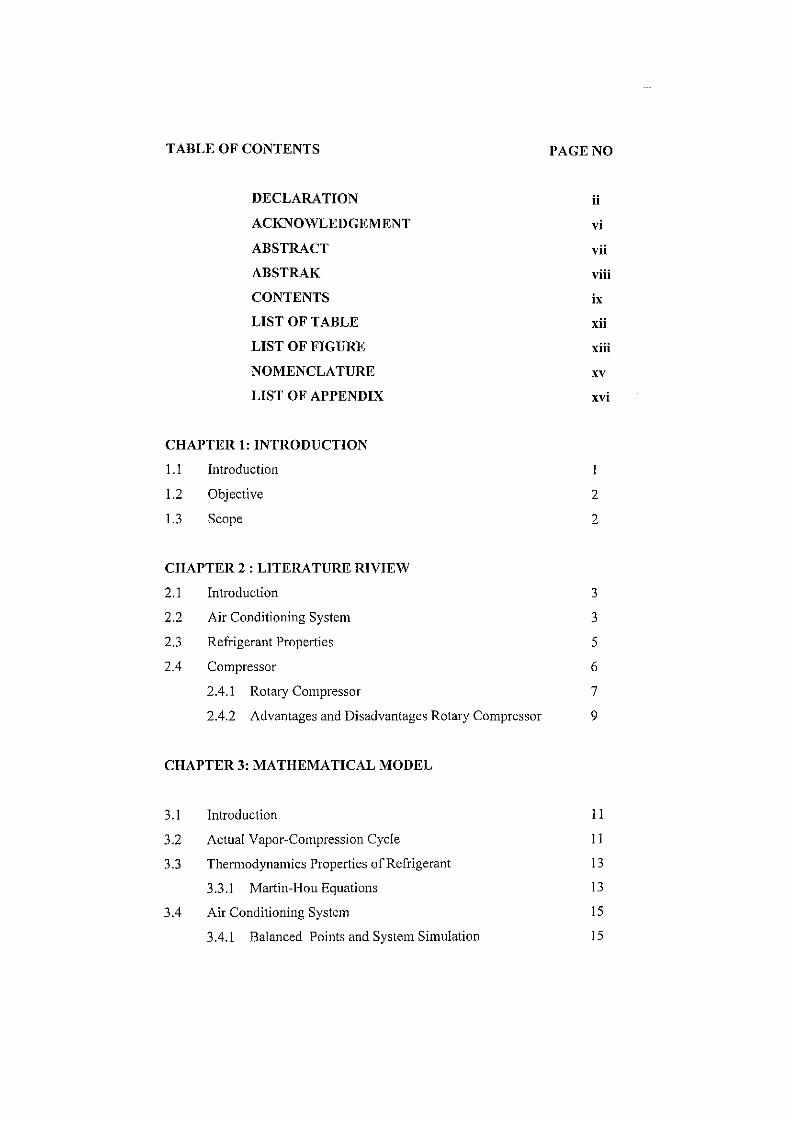
TABLE OF CONTENTS PAGE NO
DECLARATION ii
ACKNOWLEDGEMENT vi
ABSTRACT vii
ABSTRAK viii
CONTENTS ix
LIST OF TABLE xii
LIST OF FIGURE xiii
NOMENCLATURE xv
LIST OF APPENDIX xvi
CHAPTER 1: INTRODUCTION
1.1 Introduction 1
1.2 Objective 2
1.3 Scope 2
CHAPTER 2 : LITERATURE RIVIEW
2.1 Introduction 3
2.2 Air Conditioning System 3
2.3 Refrigerant Properties 5
2.4 Compressor 6
2.4.1 Rotary Compressor 7
2.4.2 Advantages and Disadvantages Rotary Compressor 9
CHAPTER 3: MATHEMATICAL MODEL
3.1 Introduction 11
3.2 Actual Vapor-Compression Cycle 11
3.3 Thermodynamics Properties of Refrigerant 13
3.3.1 Martin-Hou Equations 13
3.4 Air Conditioning System 15
3.4.1 Balanced Points and System Simulation 15
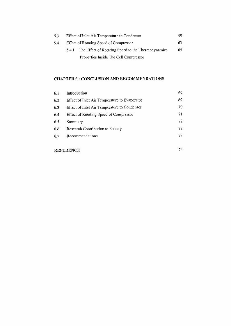
5.3 Effect of Inlet Air Temperature to Condenser 59
5.4 Effect of Rotating Speed of Compressor 63
5.4.1 The Effect of Rotating Speed to the Thermodynamics 65
Properties Inside The Cell Compressor
CHAPTER 6 : CONCLUSION AND RECOMMENDATIONS
6.1 Introduction 69
6.2 Effect of Inlet Air Temperature to Evaporator 69
6.3 Effect of Inlet Air Temperature to Condenser 70
6.4 Effect of Rotating Speed of Compressor 71
6.5 Summary 72
6.6 Research Contribution to Society 73
6.7 Recommendations 73
REFERENCE 74
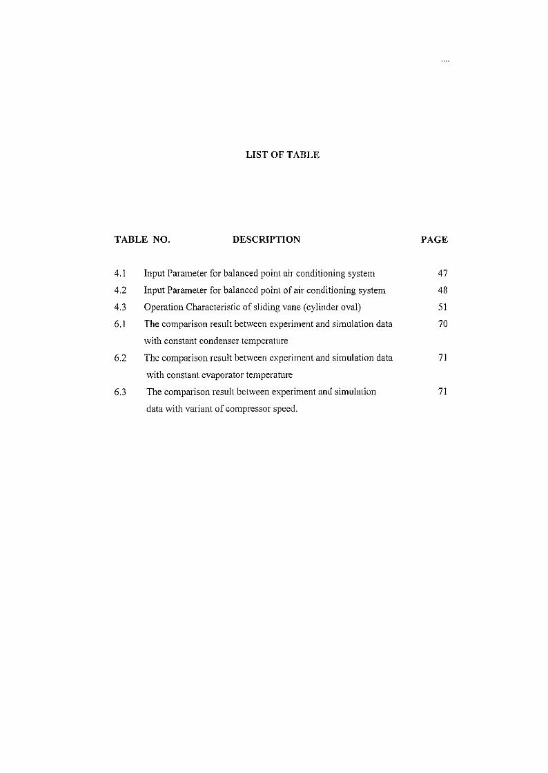
LIST OF TABLE
TABLE NO. DESCRIPTION PAGE
4.1 Input Parameter for balanced point air conditioning system 47
4.2 Input Parameter for balanced point of air conditioning system 48
4.3 Operation Characteristic of sliding vane (cylinder oval) 51
6.1 The comparison result between experiment and simulation data 70
with constant condenser temperature
6.2 The comparison result between experiment and simulation data 71
with constant evaporator temperature
6.3 The comparison result between experiment and simulation 71
data with variant of compressor speed.
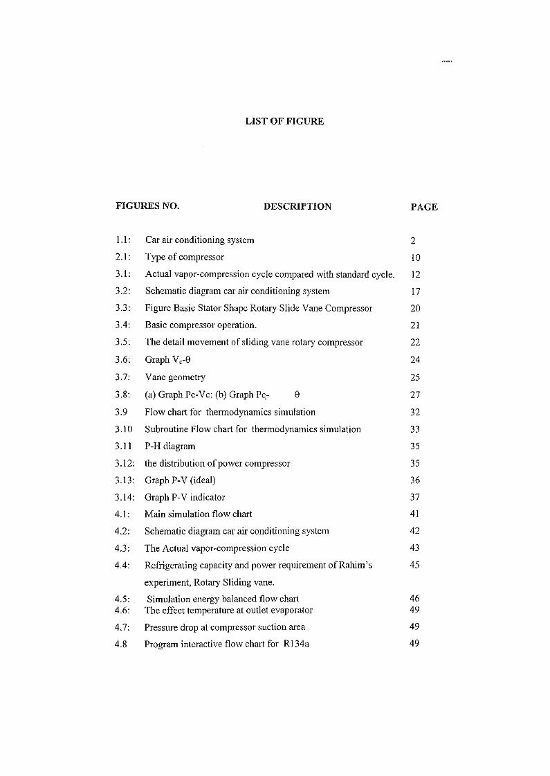
LIST OF FIGURE
FIGURES NO. DESCRIPTION PAGE
1.1: Car air conditioning system 2
2.1: Type of compressor 10
3.1: Actual vapor-compression cycle compared with standard cycle. 12
3.2: Schematic diagram car air conditioning system 17
3.3: Figure Basic Stator Shape Rotary Slide Vane Compressor 20
3.4: Basic compressor operation. 21
3.5: The detail movement of sliding vane rotary compressor 22
3.6: Graph V c-9 24
3.7: Vane geometry 25
3.8: (a) Graph Pc-Vc: (b) Graph Pc- 9 27
3.9 Flow chart for thermodynamics simulation 32
3.10 Subroutine Flow chart for thermodynamics simulation 33
3.11 P-H diagram 35
3.12: the distribution of power compressor 35
3.13: Graph P-V (ideal) 36
3.14: Graph P-V indicator 37
4.1: Main simulation flow chart 41
4.2: Schematic diagram car air conditioning system 42
4.3: The Actual vapor-compression cycle 43
4.4: Refrigerating capacity and power requirement of Rahim's 45
experiment, Rotary Sliding vane.
4.5: Simulation energy balanced flow chart 46 4.6: The effect temperature at outlet evaporator 49
4.7: Pressure drop at compressor suction area 49
4.8 Program interactive flow chart for Rl 34a 49
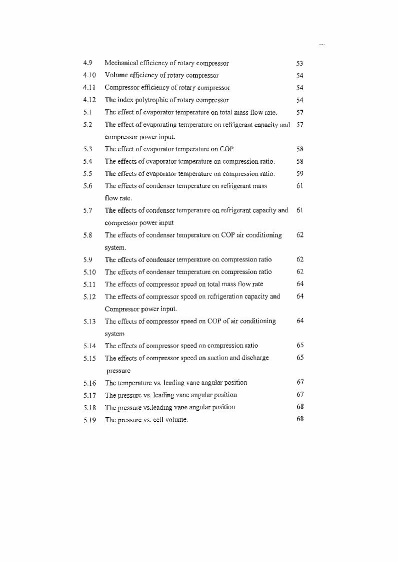
4.9 Mechanical efficiency of rotary compressor 53
4.10 Volume efficiency of rotary compressor 54
4.11 Compressor efficiency of rotary compressor 54
4.12 The index polytrophic of rotary compressor 54
5.1 The effect of evaporator temperature on total mass flow rate. 57
5.2 The effect of evaporating temperature on refrigerant capacity and 57
compressor power input.
5.3 The effect of evaporator temperature on COP 58
5.4 The effects of evaporator temperature on compression ratio. 58
5.5 The effects of evaporator temperature on compression ratio. 59
5.6 The effects of condenser temperature on refrigerant mass 61
flow rate.
5.7 The effects of condenser temperature on refrigerant capacity and 61
compressor power input
5.8 The effects of condenser temperature on COP air conditioning 62
system.
5.9 The effects of condenser temperature on compression ratio 62
5.10 The effects of condenser temperature on compression ratio 62
5.11 The effects of compressor speed on total mass flow rate 64
5.12 The effects of compressor speed on refrigeration capacity and 64
Compressor power input.
5.13 The effects of compressor speed on COP of air conditioning 64
system
5.14 The effects of compressor speed on compression ratio 65
5.15 The effects of compressor speed on suction and discharge 65
pressure
5.16 The temperature vs. leading vane angular position 67
5.17 The pressure vs. leading vane angular position 67
5.18 The pressure vs.leading vane angular position 68
5.19 The pressure vs. cell volume. 6 8
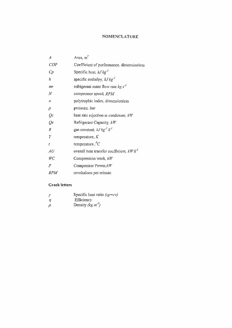
NOMENCLATURE
A Area, m2
COP Coefficient of performance, dimensionless
Cp Specific heat, kJ kg'1
h specific enthalpy, kJ kg'1
mr refrigerant mass flow rate kg s'1
N compressor speed, RPM
n polytrophic index, dimensionless
p pressure, bar
Qc heat rate rejection at condenser, kW
Oe Refrigerant Capacity, kW
R gas constant, kJ kg'1 k'1
T temperature, K
t temperature, °C
AU overall heat transfer coefficient, kWk'1
JVC Compression work, kW
P Compressor Power,kW
RPM revolutions per minute
Greek letters
y Specific heat ratio (cp=cv) rj Efficiency p Density (kg in'3)
LIST OF APPENDIX
APPENDIX . DESCRIPTION PAGE
A REFRIGERANT PROPERTIES 76
B RESULT OF AIR CONDITIONING SYSTEM 86
C PROGRAM SIMULATION 99
D SPECIFICATION OF ROTARY COMPRESSOR 115
SLIDING VANE
CHAPTER 1
EVRODUCTION
1.1 Introduction
The largest application of refrigeration, which is the process of cooling, is in
air conditioning. In the tropics an air conditioning system is widely used in vehicles
such as cars, buses, trains, trucks, recreational vehicles, air craft and ships. Its main
purpose is for comfort cooling as these vehicles are directly exposed to solar
radiation and also receive heat from other source such as human being, engine and
environment at higher temperature. The major contributions to the cooling load in the
transport are the heat from solar radiation and the heat from human especially in of
public transport. The performance of car air conditioning system is driven by the
rotation of RPM engine. The changes of rotation at high and low speed will give
significant effect to the system. According to the phenomenon, this project presents
mathematical modeling and analysis computer simulation of car air conditioning
systems with the four basic components consisting of compressor, condenser,
evaporator and expansion valve. This air conditioning system will be using a rotary
compressor with five sliding vanes because the capacity and the performance of
compressor is better compare with other compressor. Computer simulation model has
been developed and the effects of system performance are indicated by compressor
speed, pressure ratios have been evaluated.
2
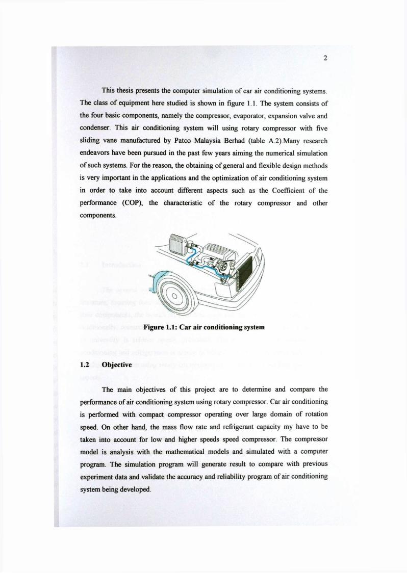
This thesis presents the computer simulation of car air conditioning systems
The class of equipment here studied is shown in figure 1 . 1 . The system consists of
the four basic components, namely the compressor, evaporator, expansion valve and
condenser. This air conditioning system will using rotary compressor with five
sliding vane manufactured by Patco Malaysia Berhad (table A.2).Many research
endeavors have been pursued in the past few years aiming the numerical simulation
of such systems. For the reason, the obtaining of general and flexible design methods
is very important in the applications and the optimization of air conditioning system
in order to take into account different aspects such as the Coefficient of the
performance (COP), the characteristic of the rotary compressor and other
components.
Figure 1 .1 : Car air conditioning system
1.2 Objective
The main objectives of this project are to determine and compare the
performance of air conditioning system using rotary compressor. Car air conditioning
is performed with compact compressor operating over large domain of rotation
speed. On other hand, the mass flow rate and refrigerant capacity my have to be
taken into account for low and higher speeds speed compressor. The compressor
model is analysis with the mathematical models and simulated with a computer
program. The simulation program will generate result to compare with previous
experiment data and validate the accuracy and reliability program of air conditioning
system being developed.
CHAPTER 2
LITERATURE REVIEW
2.1 Introduction
The several works presenting different models can be found in scientific
literature, focusing their attention on modeling typical vapor compression system,
their components, the overall refrigeration cycle and their experimental comparison.
Additionally, research work conducted by the research and engineering department
of university is seldom openly published. The history literature review of air
conditioning and refrigeration is shown in table 2.1.Research on performance of air
conditioning system using rotary compressors can be broadly classified into 3 broad
aspects.
2.2 Air Conditioning System
Davis (1972), the reference report shows the results were provided in the
form of an in-car average temperature which compared well with hot room test data.
The effect of solar loading and one occupant in the car during the actual test was
incorporated in the computer simulation. To simplify the calculation, Cheng and
4
Davis neglected the pressure drop in the components and hoses. This would account
for deviations between their results and with experimental data.
J.M. Saiz Jabardo, W. Gonzales Mamani, M.R. Ianella (2001) also studied on
a steady state computer simulation model has been developed for refrigeration
circuits of automobile air conditioning systems. An experimental bench made up of
original components from the air conditioning system of a compact passenger vehicle
has been developed in order to check the results from the model. Effects on system
performance of such operational parameters as compressor speed, return air in the
evaporator and condensing air temperatures have been experimentally evaluated and
simulated of developed model. The results deviate from the experimentally obtained
within 20% range though most of them are within 10% range. Effects of the
refrigerant inventory also have been experimentally evaluated with results showing
no effects on system performance over a wide range of refrigerant charges.
Other groups of researcher on the air conditioning system are M.Hosoz and
M.Direk (2005), the reference report shows the study deals with the performance
characteristics of an R134a automotive air conditioning system capable of operating
as an air-to-air heat pump using ambient air as a heat source. The performance
characteristics of an integrated automotive AC and air-to-air HP system using R134a
as the working fluid have been experimentally evaluated. Based on the experimental
evidence, the final conclusions reached in this study can be summarized as follows.
(a) Although the HP operation provides sufficient amounts of heat to the indoor
air stream at mild weather conditions, the heating capacity would drop at more
severe conditions due to both decreasing evaporating temperatures and activation of
the capacity control system. Therefore, an air-to-air automotive HP must be
considered only as a supplementary heating method to be used in energy efficient
automobiles lacking waste heat.
(b) Both the heating and cooling capacities of the system increase with
compressor speed, while the COPs for both cases decrease. Furthermore, the COPs
for heating outperform the COPs for cooling due to the fact that the former takes into
account the heat equivalent to the work of compression.
5
Shujun Wang, Junjie Gu, Tim Dickson, Jennifer Dexter, Ian McGregor(2005)
also agree with the finding from other researcher, the reference report shows the
results on the performance of an automotive air conditioning system with measuring
the vapor quality. The total mass flow rate increases with the increase of refrigerant
charge, evaporator air inlet temperature, and condenser water temperature also
compressor speed. The total quality at the accumulator outlet increases with the
increase of evaporator air inlet temperature, and decreases with the increase of
refrigerant charge, condenser water temperature and compressor speed. The cooling
capacity does not change with the variation of refrigerant charge, but increases with
the increase of evaporator air inlet temperature and compressor speed, and decreases
with the increase of condenser water temperature. COP of the system decreases with
the increase of refrigerant charge, condenser water temperature and compressor
speed, increases with the increase of evaporator air inlet temperature. The
compression ratio decreases with the increase of refrigerant charge and evaporator air
inlet temperature, increases with the increase of condenser water temperature and
compressor speed. The change of compressor volumetric efficiency is opposite to the
compression ratio.
Based on the research that had been done, Marcelo J.S de Lemos and Edson
Luiz Zaparoli (1996) reported on the simulation of the "steady state operation of the
four basic components of domestic refrigeration units". Based on individual
mathematical models and appropriate input parameters, equilibrium conditions are
numerically searched for all components. The simulation shows that using the
different type of the refrigerant will affect pressure at condenser and evaporator,
mass flow rate and also compressor discharge temperature.
2.3 Refrigerant Properties
I.Eames and M.Naghashzadegan (1996), reported on the computer program
was written to calculate the cycle characteristic such as cooling capacity, coefficient
of performance(COP),pressure ratio, system pressure and temperature, compressor
power for design and part load performance which is also our base of comparison.
6
This paper investigates the use of ISCEON 49, a refrigerant blend
R134a/R218/R600a (88%/9%/3%) which has thermo physical properties similar to
those R12 and R134a. It is also compatible with compressor lubricants which the
expansion valve does not need to replace and the fluid is non-flammable.
Other groups of researcher on the refrigerant properties are T.Kiasiriroat and
T.Euakit (1996) also studied on the on the "Performance analysis of an automobile
air-conditioning system with R22/R124/R152A refrigerant". A mathematical model
of each component is developed and used to simulate the system performance. The
system coefficient of performance (COP) and energy efficiency ratio (EER) increase
with the reduction of the mass fraction of R22.
Based on the research that had been done, J. Steven Brown,Samuel F. Yana-
Motta ,Piotr A. Domanski c,(2001) reported on the paper evaluates performance
merits of C O 2 and R134a automotive air conditioning systems using semi-theoretical
cycle models. The R134a system had a current-production configuration, which
consisted of a compressor, condenser, expansion device, and evaporator. The
analysis showed R134a having a better COP than C O 2 with the COP disparity being
dependent on compressor speed (system capacity) and ambient temperature. For a
compressor speed of 1000 RPM, the COP of C 0 2 was lower by 2 1 % at 32.2 °C and
by 34% at 48.9°C. At higher speeds and ambient temperatures, the COP disparity
was even greater. The entropy calculations indicated that the large entropy in the gas
cooler was the primary cause for the lower performance of C O 2 .
2.4 Compressor
Chang. K.Y. (1983), the reference thesis shows that the low pressure air
compressor in the form of air bellows were used in metallurgical processes about
5000 years ago, but there was a small development in compressor technology till
1770 when the first low air pressure compressor driven by water wheels was built .It
was not only until around 1860 that high air pressure compressors (about 6 bars)
were built. By 1888, there was widespread use of stationary air compressor both for
7
domestic and industrial purposes. Since then, high pressure compressed air became
the medium for energy distribution before the emergence of electricity distribution.
Eur.Ing.Ian M.Arbon,CEng (1994), the reference book shows that the
function of a compressor is to take a definite quantity of fluid (usually a gas, and
most often air) and deliver it at a required pressure. The most efficient machine is
one which will accomplish this with the minimum input of mechanical work. Both
reciprocating and rotary positive displacement machines are used for a variety of
purposes. The two types by defining the reciprocating type as having the
characteristics of a low mass rate of flow and high pressure ratios(up to 500 bar and
above) and the rotary type as having a high mass rate flow and low pressure ratios.
The pressure range of atmospheric about 9 bars is common to both types. Over the
years a number of different types have evolved and there is now a wide variety of
compressor, as shown in figure 2.1
2.4.1 Rotary Compressor
Whittaker Hall (1936), the history of rotary type compressor started with the
development of the sliding vane compressor in 1930. This took the form of the
Witting compressor design by R.S Witting and built and mass produced by Whittaker
Hall in 1936.These machines operated at pressures up to 7 bar (100 lbf/in2) using 2
stages, but were inefficient, losing most of the power through friction between the
vanes and the stator. It was not until around 1946 that oil injection was introduced, a
solution proposed by Major P.C. Bird. Thus started the age of the oil-flooded rotary
sliding vane compressor produced by Alfred Bullows Ltd, and first mass produced
by Whittaker Hall in 1952. Since then, developments have been made and continue
to be made especially in the areas of increased operating pressure and increased flow.
(a) Mathematical Modeling and Computer Simulation
Maruyama (1982), reported on the "Capacity Control of Rotary Type
Compressor for Automotive Air-Conditioners'. The journal is discussed about the