rtstt m t iU.jYv.r.t i-i iH't ->r;: ppy;r * t...
24
i-i iH'ti. ; ->r;: ppy;r * t rtstt m t. iU.jYv.rt Y " • •"• •'•• t ' !• • A i A ; t i Jui /ll >;•'->'{iJ ji: i-.K DSM T't i'i ft ii k k y/'.i: t a^nr&vm w ruisi UM9W4 flMN hUl.i; J U-'Vs t jv^C'S: S 1 ••i^ULU^? I UW » h*
Transcript of rtstt m t iU.jYv.r.t i-i iH't ->r;: ppy;r * t...
i-i iH'ti.; ->r;: ppy ; r * t rtstt m t. iU.jYv.rt
Y " • •"• •'•• t ' !• • A i A ; t i Jui / l l
>;•'->'{iJ ji: i-.K DSM T't i'i ft ii k k
y / ' . i : t a ^ n r & v m w ruisi U M 9 W 4 flMN hUl.i; J U-'Vs t jv^C'S: S 1 • • i ^ U L U ^ ? I UW » h*

I I I t 1 • 1 f I i t I, r i l l
i i ! : I II !
D I M M l I H I I I . . | '
KOLEJ UNIVERSITITEKNOLOGI TUN HUSSEIN ONN
BORANG PENGESAHAN STATUS TESIS4
JUDUL: MITIGATION OF A M INTERFERENCE IN DIGITAL TRANSMISSION SESIPENGAJIAN: 2003/2004
Saya ERWAN BIN SULAIMAN (HURUF BESAR)
mengaku membenarkan tesis (Saijana Muda/Saijana /Doktor Falsafah)* ini disimpan di Perpustakaan dengan syarat-syarat kegunaan seperti berikut:
1. Tesis adalah hakmilik Kolej Universiti Teknologi Tun Hussein Onn. 2. Perpustakaan dibenarkan membuat salinan untuk tujuan pengajian sahaja. 3. Perpustakaan dibenarkan membuat salinan tesis ini sebagai bahan pertukaran antara institusi
pengajian tinggi. 4. **Silatandakan( V )
SULIT
TERHAD
(Mengandungi maklumat yang berdaijah keselamatan atau kepentingan Malaysia seperti yang termaktub di dalam AKT A RAHSIA RASMI1972)
(Mengandungi maklumat TERHAD yang telah ditentukan oleh organisasi/badan di mana penyelidikan dijalankan)
TIDAK TERHAD
Disahkan oleh:
(TANDATANGAN PENULIS)
Alamat Tetap:
NO. 44 JALAN BUNGA ROS. KG. DATO SULAIMAN MENTERI, 81100 JOHOR BAHRU. JOHOR
PROF. PR. MQHD ZARAR BIN MOHD JENU ( Nama Penyelia )
Tarikh: 23 MARCH2004 Tarikh: 23 MARCH2004
CATATAN: * Potong yang tidak berkenaan. ** Jika tesis ini SULIT atau TERHAD, sila lampirkan surat daripada pihak
berkuasa/organisasi berkenaan dengan menyatakan sekali tempoh tesis ini perlu dikelaskan sebagai atau TERHAD.
• Tesis dimaksudkan sebagai tesis bagi Ijazah doktor Falsafah dan Saijana secara Penyelidikan, atau disertasi bagi pengajian secara kerja kursus dan penyelidikan, atau Laporan Projek Saijana Muda (PSM).
"I hereby acknowledge that the scope and quality of this thesis is qualified for the
award of the Master Degree of Electrical Engineering"
Signature
Name : PROF. DR. MOHD ZARAR BIN MOHD JENU
Date : 23 MARCH 2004
MITIGATION OF AM INTERFERENCE IN
DIGITAL TRANSMISSION
ERWAN BIN SULAIMAN
A project report submitted as partial fulfillment of the requirements for the
award of the Master Degree of Electrical Engineering
Department of Electrical Engineering
Faculty of Engineering
Kolej Universiti Teknologi Tun Hussein Onn
MARCH, 2004
ii
"All the trademark and copyrights use herein are property of their respective owner.
References of information from other sources are quoted accordingly; otherwise the
information presented in this report is solely work of the author."
Signature
Author : ERWAN BIN SULAIMAN
Date 23 MARCH 2004
Tor My MotherJLsiah (Binti JumaCi,
My Father Sutaiman (Bin Nairn,
JLmfMy Fiance Jfoor JLzradiana (Binti Zahari with Love,
iv
ACKNOWLEDGEMENT
I would like to express my gratitude to my supervisor, Professor Dr Mohd
Zarar Bin Mohd Jenu for his guidance and help rendered throughout this project. His
willingness to teach attitude and unfailing patience has been a great motivation for
me to excel in my work. Without his guidance and invaluable time spent, this thesis
would not have been completed successfully.
To Mrs. Rosila, Mr. Nazri, Mr. Aizan and others whose name could not be
mentioned here one by one. Your encouragement and concern is greatly appreciated.
Finally, I would like to thank God for giving me this wonderful privilege to
work on my project and entire lesson I've learned along the way. Surely it is an
experience which will prove invaluable later in life.
X
ABSTRACT
The plain-old-telephone-system (POTS) is now increasingly used to carry
high-speed data such as for Internet purpose. However, problem can occur if the
telephone network is in close proximity to an AM radio transmitter, transmitting
high power signal at a frequency which overlaps the bandwidth of the Internet
transmission. The interfering electromagnetic field can induced enough current and
voltage in the telephone network and causing significant data errors. This report
presents a study on the effects of high-powered AM transmission at 576 kHz on a
digital transmission system. A GTEM Cell was used to generate the 576kHz clectric
field intensity varying from lV/m to 15 V/m with 80% amplitude modulation. The
electric field is imposed on a section of the cable and the Bit Error Rate (BER) is
noted using Data Tools 5000. Shielding technique was employed using four
conducted materials (soft steel, hard steel, aluminum and copper) in order to test the
attenuation of the electric field reaching the cable. Measured results showed that
copper ( a = 5.87 x 10⁷ S/m, fr =1) can reduce up to 70% of the BER. The
relationship between electric field E and BER for copper is expressed as
BER = 2 x 10~5 e0-3"^' +2 .48x10"^ indicating that the BER increases exponentially
with the magnitude of the applied electric field. It is obvious from the work done in
this project that any network situated near a high-powered electromagnetic field
transmitter should employ a good shielded cabling system. It is recommended that
further study need to be carried out to find ways of mitigating the effects of the
interfering field such filtering and grounding.
vi
ABSTRAK
Penggunaan plain-old-telephone-system (POTS) pada masa kini semakin
meningkat terutama untuk membawa data kelajuan tinggi seperti Internet. Walau
bagaimanapun, masalah akan timbul sekiranya sistem ini terletak berhampiran
pemancar radio AM yang memancarkan isyarat dengan kuasa tinggi terutama pada
frekuensi yang bertaut dengan lebaijalur penghantaran Internet. Gangguan medan
elektromagnet boleh menghasilkan arus dan voltan ke dalam rangkaian telefon dan
menyebabkan kesilapan data. Tesis ini menerangkan kesan kuasa tinggi
penghantaran AM pada 576 kHz keatas sistem penghantaran digital. GTEM Cell
digunakan untuk menghasilkan 576 kHz keamatan medan elektrik diantara 1 V/m
hingga 15 Y/m dengan 80% perubahan amplitud. Medan elektrik dikenakan keatas
sebahagian kabel penghantaran dan Kadar Kesilapan Bit (BER) dicatat
menggunakan Data Tools 5000. Kaedah pelindung digunakan dengan empat bahan
pengalir (besi lembut, besi keras, aluminium dan kuprum) untuk menguji keamatan
medan elektrik yang menghampiri kabel. Keputusan ujikaji menunjukkan kuprum
(a= 5.87 x 10⁷ S/m, =1) dapat mengurangkan sehingga 70% BER. Hubungan
antara medan elektrik |i?| dan BER untuk kuprum ialah
BER = 2x10 5 e ' ' + 2 . 4 8 x 1 0 5 ^ menunjukkan bahawa BER meningkat secara
eksponen dengan peningkatan magnitud medan elektrik. Ujikaji yang dijalankan
menunjukkan dengan jelas bahawa setiap sistem yang berdekatan dengan pemancar
medan elektromagnet kuasa tinggi mesti menggunakan kaedah pelindung kabel yang
baik. Adalah dicadangkan bahawa kajian lebih mendalam harus dibuat untuk
mancari cara mangatasi gangguan medan elektrik seperti kaedah penapis dan
pembumian.
v i i
TABLE OF CONTENTS
CHAPTER TITLE PAGE
DECLARATION ii
DEDICATION iii
ACKNOWLEDGEMENT iv
ABSTRACT v
ABSTRAK vi
TABLE OF CONTENTS vii
LIST OF FIGURES x
LIST OF TABLES xii
GLOSSARY OF ABBREVIATIONS xiii
LIST OF APPENDIX xv
CHAPTER 1 INTRODUCTION 1
1.1 Project Introduction 1
1.2 Problem Statement 3
1.3 Objectives 3
1.4 Scope of Work 4
1.5 Importance of Project 4
V l l l
CHAPTER 2 LITERATURE REVIEW 6
2.1 Introduction to Broadcast Signal 6
2.1.1 AM Radio 7
2.2 Introduction to ADSL 8
2.2.1 ADSL Technology 9
2.2.2 ADSL Spectrum and Bit Allocation 11
2.2.3 ADSL Modulation and Coding 12
2.3 Radiated susceptibility models on wires 14
2.4 Shielding 19
2.4.1 Characteristic and wave impedance 21
2.4.2 Shielding Effectiveness 22
2.4.3 Absorption Loss 25
2.4.4 Reflection Loss 29
2.5 Previous Works 34
CHAPTER 3 METHODOLOGY 43
3.1 Introduction 43
3.2 Research Procedure 44
3.3 Baseband Modem 46
3.3.1 Artificial Lines, Noise Generator,
Data/Frequency Generator I/O 48
3.4 Data Tool 5000 50
3.5 Gigahertz Transverse Electromagnetic Mode
(GTEM) Cell 51
3.5.1 GTEM Concept 52
i x
CHAPTER 4 RESULTS AND DISCUSSION 54
4.1 Introduction 54
4.2 Electric Field Calculation 55
4.3 BER with Increasing Noise Level 58
4.4 BER with Different Material Used for Shielding 59
4.5 BER with Shielded Material for Different
Polarization (x, y, z-axis) 62
4.6 Discussion 64
CHAPTER 5 CONCLUSION AND RECOMMENDATIONS 66
5.1 Conclusion 66
5.2 Recormr endations 67
REFERENCES 68
APPENDIX A 71
APPENDIX B 81
APPENDIX C 85
APPENDIX D 92
APPENDIX E 96

X
LIST OF FIGURE
FIGURE NO. TITLE PAGE
1.1 Aspect of EMC issue 2
2.1 Radio frequency bands 6
2.2 AM radio carrier wave 8
2.3 ADSL Spectral allocation 10
2.4 ADSL network. 11
2.5 A transmitter using discrete multi-tone 13
2.6 Modeling a two-conductor line to determine voltages induced by
an incident electromagnetic field 16
2.7 A simplified lumped equivalent circuit of the pickup of incident electric
fields for a two-conductor line that is very short, electrically 19
2.8 Shield application where a noise source is contained, preventing
interference with equipment outside the shield 20
2.9 Shield application where interference is prevented by placing a shield
around a receptor to prevent noise infiltration 20
2.10 The incident magnetic field induces in the conductor, producing an
opposing field to cancel the incident field in the region enclosed by the
shield. 23
2.11 Electromagnetic wave passing through an absorbing medium
is attenuated exponentially 26
2.12 Absorption loss increase with frequency and shield thickness 29
2.13 An incident wave is partially reflected from, and partially transmitted
through, an interface between two media 30
xv
2.14 Partial reflection and transmission occur at both faces of shield ?2
2.15 Analog Narrowband RFI canceling 4 0
2.16 Digital wideband adaptive common-mode noise canceller 42
3.1 Methodology 45
3.2 Baseband Modem 49
3.3 GTEM Cell 52
3.4 Immunity setup for GTEM Cell 53
4.1 Electric Field Intensity versus Distance 55
4.2 Model for Electric Field with Angle (6P) 56
4.3 Electric Field Intensity versus Angle ( j f ) For a Cable Distance
500m from Antenna 57
4.4 BER versus Time with Different Noise Level without Electric Field
Interfere to the System 58
4.5 BER versus Noise (Level 1-10) 59
4.6 BER versus Electric Field for >: -axis 60
4.7 BER versus Electric Field for y-axis 61
4.8 BER versus Electric Field for z-axis 61
4.9 BER versus Electric Field in x, y, z polarization
(Soft Steel ar=0.1, p, =1000, thickness 0.15cm) 62
4.10 BER versus Electric Field in x, y, z polarization
(Hard Steel or=0.1, =1000, thickness 0.22cm) 63
4.11 BER versus Electric Field in x, y, z polarization
(Aluminum ar=0.61, ji,- =1, thickness 0.25cm) 63
4.12 BER versus Electric Field in x, y, z polarization
(Copper CTr=l, jir =1, thickness 0.2cm) 64
xi i
LIST OF TABLE
2.1 Relative Conductivity and Permeability of Various Materials 28
2.2 Performance of feedforward and feedback noise reduction techniques 37
3.1 Data Tool Results 50
4.1 Materials used for shielding 59
4.2 BER Percentage for Different Materials and Polarization 65
xi i i
GLOSSARY OF ABBREVIATIONS
E - Electric Field (V/m)
B - Magnetic Flux (T)
f - Frequency (f)
H - Magnetic Field (H/m)
J - Current Density
jir . Relative Permeability
c r . Relative Conductivity
S - Shielding Effectiveness
Z - Impedance (D)
AC - Alternating Current
ADSL - Asymmetric Digital Subscriber Line
AM - Amplitude Modulation
ATM - Asynchronous Transfer Mode
ATU - ADSL Terminal Unit
BER - Bit Error Rate
BERT - Bit Error Rate Tests
CB - Citizens Band
CE - Conducted Emission
CM - Common Mode
CO - Central Office
DC - Direct Current
DM - Differential Mode
DMT - Discrete Multi Tone
EMC - Electromagnetic Compatibility
EMI - Electromagnetic Interference
XIV
EMS Electromagnetic Susceptibility
ESD Electrostatic Discharges
EUT Equipment under Test
FCC Federal Communications Commission
FDD Frequency Division Duplex
FEC Forward Error Correction
FEXT Far End Crosstalk
FFT Fast Fourier Transform
FM Frequency Modulation
GTEM Gigahertz Transverse Electromagnetic
HF High Frequency
JMLSE Joint Maximum Likelihood Sequence Estimation
MMSE Minimum Mean-Square Error
NEXT Near End crosstalk
NID Network Interface Device
POTS Plain Analog Telephone Service
RF Radio Frequency
RFI Radio Frequency Interference
RT Remote Terminal
SNR Signal to Noise Ratio
XV
LIST OF APPENDIX
APPENDIX TITLE PAGE
A Analysis 71
B Experimental Setup 81
C Modem Technical Characteristic 85
D Transmission Circuit 92
E Data Tools 5000 Manual 96
<1
CHAPTER 1
INTRODUCTION
1.1 Introduction
The widespread use of electronic circuits for communication, computation,
automation and other purposes makes it necessary for diverse circuits to operate in close
proximity. All too often, these circuits affect each other adversely. Electromagnetic
interference (EMI) has become a major problem for circuit designers, and it is likely to
become more severe in the future. The large number of electronic devices in common
use is partly responsible for this trend. In addition, the use of integrated circuits and
large-scale integration has reduced the size of electronic equipment. As circuitry has
become smaller and more sophisticated, more circuits are being crowded into less
space, thus increasing the probability of interference.
Today's equipment designers need to do more than just make their systems
operate under ideal conditions in the laboratory. Besides that obvious task, they must
also make sure the equipment will actually work in the "real world" with other
21
equipment nearby. This means that the equipment should not be affect by external noise
sources, and should not it be a source of noise to the environment. Electromagnetic
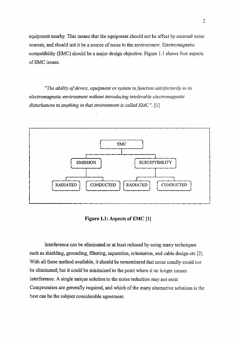
compatibility (EMC) should be a major design objective. Figure 1.1 shows four aspects
of EMC issues.
"The ability of device, equipment or system to Junction satisfactorily in its
electromagnetic environment without introducing intolerable electromagnetic
disturbances to anything in that environment is called EMC". [1]
Figure 1.1: Aspects of EMC [1]
Interference can be eliminated or at least reduced by using many techniques
such as shielding, grounding, filtering, separation, orientation, and cable design etc [2],
With all these method available, it should be remembered that noise usually could not
be eliminated; but it could be minimized to the point where it no longer causes
interference. A single unique solution to the noise reduction may not exist.
Compromises are generally required, and which of the many alternative solutions is the
best can be the subject considerable agreement.
1.2 Problem Statement
New digital technologies operate at high frequencies is an economical
alternative to deliver broadband services over the existing copper access network. In
order to be successful, digital transmission will have to deal with a number of
impairments that exist in the local loop. The focus is on interference from and into radio
users. Because digital signals contain frequencies up to several megahertz, these
broadband signals are susceptible to more hostile noise conditions such as radio system.
In this study we will discuss the interference and noise reduction techniques due to AM
radio system that used 576 kHz frequencies; with 73dBm (20kW) power which happen
into digital transmission.
1.3 Objectives
The project objectives are as follows: -
(i) To determine effect of high power AM signal in digital transmission
(ii) To identify the potential techniques in reducing the electromagnetic
interference.
(iii) To do experimental measi rements and testing on the performance of the
mitigation techniques.
4
1.4 Scope of Work
The scope of the project is as follows :
(i) Use base band modem mod. BM/EV and data tools 5000 to test
interconnection cables, terminals and transmission lines for twisted pan-
cables
(ii) To do immunity measurement on the twisted pair cables using Gigahertz
Transverse Electromagnetic Cell (GTEM Cell) with 576 kHz frequency
of AM signal.
(iii) Only shielding technique is used.
(iv) Analysis the shielding concept with various materials and polarization.
1.5 Importance of Project
(i) To understand the behavior of the electromagnetic interference due to
AM transmission.
(ii) Propose to manufacturer to upgrade the twisted pair cable using shielded
material in high electromagnetic interference area.
<5
CHAPTER II
LITERATURE REVIEW
2.1 Introduction to Broadcast Signal
Radio communication is typically in the form of AM radio or FM Radio
transmissions. The broadcast of a single signal, such as a monophonic audio signal,
could be done by straightforward amplitude modulation or frequency modulation. A
radio wave is an electromagnetic wave propagated by an antenna. Radio waves have
different frequencies, and by tuning a radio receiver to a specific frequency (Figure 2.1)
we can pick up a specific signal.


![repository.psa.edu.myrepository.psa.edu.my/bitstream/123456789/1319/1... · Alir masuk secara mekanikal dan alir keluar secara semulajadi [10 marks] [10 markah] Sketch the diagram](https://static.fdokumen.site/doc/165x107/6083e2d6a3ac3c45d36229f7/alir-masuk-secara-mekanikal-dan-alir-keluar-secara-semulajadi-10-marks-10-markah.jpg)