THE MECHANISM OF FAILURE OF STRUCTURAL...
24
iii THE MECHANISM OF FAILURE OF STRUCTURAL LIGHTWEIGHT CONCRETE INFILL OF IBS BLOCKS SUBJECTED TO FLEXURAL MUGAHED YAHYA HUSSEIN AMRAN A project report submitted in partial fulfillment of the requirements for the award of the degree of Master of Engineering (Civil & Structure) Faculty of Civil Engineering Universiti Teknologi Malayisia JANUARY 2013
Transcript of THE MECHANISM OF FAILURE OF STRUCTURAL...

iii
THE MECHANISM OF FAILURE OF STRUCTURAL LIGHTWEIGHT
CONCRETE INFILL OF IBS BLOCKS SUBJECTED TO FLEXURAL
MUGAHED YAHYA HUSSEIN AMRAN
A project report submitted in partial fulfillment of the
requirements for the award of the degree of
Master of Engineering (Civil & Structure)
Faculty of Civil Engineering
Universiti Teknologi Malayisia
JANUARY 2013

v
أهــــــــــــــــــــــــداء:
في عليين بجوار النبيين والمرسلين من شجعني في صغــرى الي من رحمه هللا تغشــــــــاه واسكنه
(أبي)
عث فيني الهمهظني ومن صوتها وحنانها يبجي ربي ان يحفآفع يداها تنترعد أن ب الي من لم تنام عيناها اال
(أمي)
في سبيل تحقيق أهدافي المرسومه دا لي سن واالي من ساعدوني ووقفوا بجانبي ورفعوا معنوياتي وكان
(واتيخأخواني وأ)
وكانوا نوأبا عن أخواني لي بالغربه –أنسجمت بمصادقتهم و غربتيأحلي لحظات الي من من عشت معهم
(أصدقائيو ي ئزمال)
To my parents and all my beloved family members

vi
ACKNOWLEGEDMENT
In the beginning, I would love to express my greatest and sincere appreciation
to my final master project supervisor and con-supervisor; Ir. Azhar Bin Ahmad and
PM. Dr. Abdul Kadir Marsono respectively, for their guidance, critics,
encouragement, and advises throughout the process of this research. I am indebted to
them for their valuable instructions and guidance along the time of the research. I am
truly grateful to them also in the confidence and trust on me from the beginning of
the project until the stage of research accomplishment.
I am very grateful to have my friends with me during the period of research
preparation whenever I face any obstacles and problems; they always give their
moral support and encouragement to me throughout the process of research and
greatly indebted to all my beloved family members for their consistent
encouragement me and support every moment.
Last but not least, I also would like to thank to my friends who always
accompany me and give their moral support when in need especially those involved
directly or indirectly in my preparation of research. Their opinions and views are
useful indeed. May our friendship last forever and I will keep always praying that
may ALLAH guide them and me to the right path and help us to serve and develop
our nations.

vii
ABSTRACT
Currently there is a strong inclination of the Malaysian construction industry
to utilize industrialized building system (IBS) of lightweight concrete material. The
use of lightweight material has the potential to offset the high cost of production and
transportation of IBS components of normal dense concrete material. This research
presents an experimental contacted testing on the mechanism of failure of structural
lightweight concrete infill of IBS block-works subjected to flexural. Full-scale
experimental push-out test frames were erected to investigate the ultimate behavior
of lightweight concrete beams and blocks. The setup frame consists of lightweight
beams supported at both ends with IBS lightweight infill blocks. Numerous
dimensions and shapes of the lightweight IBS blocks were tested. Each lightweight
IBS blocks were designed based on readily available steel formwork and proper
means of fixing and assembling each IBS blocks to form a complete a full height
lightweight panel. Push-out load (flexural load) is then applied up to failure to
determine the behavior of the IBS panel due to incremental loading. The deflection,
crack pattern, splitting strength, tensile strength and ultimate compressive strengths
of the IBS blocks are recorded and compared with the results obtained with a similar
panel of normal concrete in-fill.

viii
ABSTRAK
Sekarang ini, terdapat kecenderongan dikalangan industri pembinaan di
Malaysia untuk menggunakan Sistem Binaan Berindustri (IBS) yang menggunakan
bahan konkrit ringan. Tidak seperti konkrit biasa, penggunaan konkrit ringan
mempunyai potensi untuk menjimat kos yang tinggi bagi pengeluaran dan
pengangkutan komponen IBS ini. Kajian ini membentangkan ujian eksperimen
dihubungi mengenai mekanisme kegagalan struktur konkrit ringan blok IBS tertakluk
kepada lenturan. Suatu kerangka tolak-keluar yang berskala penuh telah didirikan
untuk meninjau tingkah laku muktamad rasuk dan blok konkrit ringan. Kerangka
yang dibina ini terdiri daripada rasuk ringan yang disokong pada kedua-dua
hujungnya dengan infill blok konkrit ringan IBS. Pelbagai dimensi dan bentuk blok
IBS ringan telah diuji. Setiap blok ringan IBS telah direka bentuk berdasarkan acuan
keluli yang sedia ada dan menggunakan kaedah pemasangan yang betul bagi setiap
blok IBS untuk membentuk panel ringan yang lengkap dengan ketinggian penuh.
Suatu beban sisi kemudian dikenakan sehingga tahap kegagalan untuk menentukan
tingkah laku panel IBS semasa penambahan bebanan. Bacaan pesongan, corak retak,
kekuatan pemisahan, kekuatan tegangan dan kekuatan mampatan muktamad blok
IBS direkod dan perbandingan dibuat dengan keputusan yang diperolehi daripada
panel infill konkrit biasa yang serupa.

ix
TABLE OF CONTENTS
CHAPTER TITLE PAGES
TITLE i
DECLARATION iv
ACKNOWLEDGEMENT vi
ABSTRACT vii
ABSTRAK viii
TABLE OF CONTENT ix
LIST OF TABLES xiv
LIST OF FIGURES xv
LIST OF ABBREVIATION xvii
LIST OF APPENDIX xix
1 INTRODUCTION ....................................................................................... 1
1.1 Background ................................................................................................... 1
1.2 Problem statements ....................................................................................... 4
1.3 Objectives of research ................................................................................... 5
1.4 Significance of study ..................................................................................... 5
1.5 Scope of study ............................................................................................... 6

x
2 LITERATURE REVIEW .......................................................................... 7
2.1 Introduction ................................................................................................... 7
2.2 Background of aerated aggregates (Pumice aggregate) ................................ 9
2.3 Classification of lightweight concrete materials ......................................... 10
2.3.1 Low density concrete ........................................................................... 10
2.3.2 Moderate strength concrete .................................................................. 10
2.3.3 Structural concrete ............................................................................... 11
2.4 Comparison between the three types of lightweight aggregate ................... 13
2.5 Application of lightweight concrete ............................................................ 14
2.6 Advantages and disadvantages of lightweight Concrete ............................. 15
2.7 IBS concrete block production methods ..................................................... 16
2.7.1 Fully Prefabricated Construction Method ............................................ 17
2.8 Characteristics of Precast Concrete beams and blocks ............................... 18
2.8.1 Aerated Concrete Blocks ..................................................................... 19
2.8.2 Stability of IBS pre-cast beams ............................................................ 20
2.9 Basic Beam behavior ................................................................................... 20
2.9.1 Beam tension behavior ......................................................................... 21
2.9.2 Beam compression behavior ................................................................ 22
2.9.3 Beam behavior with two different forces direction. ............................ 23
2.10 Micro-structural behavior for aerated concrete aggregate beam and block 24
2.10.1 Compressive strength ........................................................................... 24
2.10.2 Modulus of elasticity (E) ..................................................................... 25
2.10.3 Splitting tensile strength ...................................................................... 26
2.10.4 Tensile and Flexural tensile strength ................................................... 27
2.10.5 Deflections ........................................................................................... 27
2.10.6 Density ................................................................................................. 28
2.11 Structural Lightweight concrete mix design mechanisms ........................... 29

xi
2.11.1 Ordinary Portland cement content ....................................................... 29
2.11.2 Water content ....................................................................................... 30
2.11.3 Sand ...................................................................................................... 30
2.11.4 Admixture ............................................................................................ 31
2.11.5 Super-plasticizers ................................................................................. 31
2.12 Aerated structural lightweight aggregate concrete related tests .................. 32
2.12.1 At fresh state ........................................................................................ 32
2.12.2 At hardened state .................................................................................. 33
2.13 Behavior of reinforced concrete blocks and beams with lightweight infill 34
2.14 Role of infill walls in response of moment-frame buildings ....................... 35
2.15 Structural lightweight concrete behavior .................................................... 36
2.15.1 Fire Resistance and spall Defect to L.W.C .......................................... 36
2.15.2 Freezing and thawing ........................................................................... 36
2.15.3 Abrasion resistance .............................................................................. 37
2.15.4 Chemical attack .................................................................................... 37
2.15.5 Acid resistance ..................................................................................... 38
2.15.6 Alkali aggregate resistance .................................................................. 38
2.15.7 Carbonation and corrosion ................................................................... 39
3 RESEARCH METHODOLOGY AND PROCEDURE ........................ 40
3.1 Introduction ................................................................................................. 40
3.2 Experimental procedures (Program) ........................................................... 42
3.3 Experimental materials used ....................................................................... 44
3.3.1 OPC Cement ........................................................................................ 44
3.3.2 Sand ...................................................................................................... 45
3.3.3 Aerated aggregates ............................................................................... 45
3.3.4 Water .................................................................................................... 47

xii
3.3.5 Plasticizers ........................................................................................... 48
3.4 Experimental specimens preparation........................................................... 49
3.4.1 Mix composition (concrete mix) .......................................................... 49
3.4.2 Mould & ready formwork .................................................................... 49
3.4.3 Lightweight concrete mix design mixer............................................... 51
3.4.4 Concrete transportation and placing processes .................................... 51
3.4.5 Concrete vibrating ................................................................................ 52
3.4.6 Curing samples ..................................................................................... 55
3.4.7 Test methods ........................................................................................ 56
4 RESULTS, DISCUSSION AND ANALYSIS ......................................... 65
4.1 Introduction ................................................................................................. 65
4.2 Compression test ......................................................................................... 66
4.3 Experimental tests analysis ......................................................................... 67
4.3.1 Splitting test ......................................................................................... 67
4.3.2 E-value test ........................................................................................... 69
4.4 Frame analysis ............................................................................................. 73
4.4.1 Load versus Deflection Relationship ................................................... 73
4.4.2 Load and deflection relationship at cycle 1 ......................................... 74
4.4.3 The maximum load verse deflection at first cycle 1 ............................ 75
4.4.4 Load and deflection relationship at cycle 2 ......................................... 75
4.4.5 The maximum load verse deflection at second cycle 2 ....................... 76
4.4.6 Load and deflection relationship at cycle 3 ......................................... 77
4.4.7 The maximum load verse deflection at the three cycles ...................... 78
4.4.8 The maximum load verse deflection at the cycle 3 .............................. 79
4.4.9 Load verse deflection at point load 1 ................................................... 80
4.4.10 Load verse deflection at point load 2 ................................................... 81

xiii
4.5 Comparison between lightweight concrete and a normal concrete in-fills
results .................................................................................................................... 82
4.6 Mode of failure and cracking outline .......................................................... 85
4.6.1 Cracking outline ................................................................................... 86
4.6.2 Mode of failure .................................................................................... 90
4.7 Manufacturing Problems ............................................................................. 94
4.8 Assembly and erection problems ................................................................ 95
5 CONCLUSION AND RECOMMENDATIONS .................................... 97
5.1 Conclusion ................................................................................................... 97
5.2 Recommendations ....................................................................................... 99
REFERENCES ....................................................................................................... 100
APPENDIXS A - D 102 - 111

xiv
LIST OF TABLES
CHAPTER TITLE PAGE
2.1 Pumice aggregate properties ............................................................. 9
2.2 Chemical analysis of pumice aggregates ........................................ 10
2.3 Comparisons between the three types of lightweight aggregate ..... 13
2.4 Advantages and disadvantages of lightweight Concrete ................ 15
4.1 Load verse deflection at point load 1 .............................................. 81
4.2 Load verse deflection at point load 2 .............................................. 82
4.3 Frame Load verse deflection measure at point load 1 .................... 83
4.4 Frame Load verse deflection measure at point load2 ..................... 84
4.5 Frame Load verse deflection measure at point load 3 .................... 84

xv
LIST OF FIGURES
CHAPTER TITLE PAGE
1.1 IBS lightweight concrete block .................................................... 6
2.1 Aerated aggregate ....................................................................... 12
2.2 Connection of beam and block-work .......................................... 12
2.3 Compressive Strength ................................................................ 15
2.4 IBS block production methods ................................................... 17
2.5 Fully prefabricated construction method ................................... 18
2.6 General beam action behavior.................................................... 21
2.7 Beam tension behavior ............................................................... 22
2.8 Beam compression behavior ...................................................... 22
2.9 The forces behavior on beam ..................................................... 23
2.10 Beam shear force and bending moment ..................................... 24
2.11 Splitting tensile strength vs tested compressive strength ........... 26
2.12 Deflection graph for frame load ................................................. 28
2.13 Lightweight concrete infill wall ................................................. 35
2.14 Schematic representation of carbonation process ...................... 39
3.1 Laboratory work flow ................................................................ 42
3.2 OPC cement ................................................................................ 44
3.3 Sand ............................................................................................. 45
3.4 Aerated aggregates ...................................................................... 46
3.5 Water ........................................................................................... 48
3.6 Plasticizers .................................................................................. 48

xvi
3.7 Cylinder cube mould ..................................................................... 50
3.8 Beam ready formwork .................................................................. 50
3.9 Electric motor powered reverse concrete mixer ........................... 51
3.10 concrete transportation and placing process ................................. 52
3.11 concrete vibration process ............................................................. 53
3.12 Fresh Concrete after Casting ......................................................... 54
3.13 fresh cylinder cube samples .......................................................... 54
3.14 curing process of IBS blocks & beam ........................................... 55
3.15 curing process of cylinder cubes ................................................... 56
3.16 The compression test machine ...................................................... 57
3.17 splitting test ................................................................................... 58
3.18 E-value test .................................................................................... 59
3.19 The flexural test (push-off test) setup ........................................... 60
3.20 The test specified point loads ........................................................ 61
3.21 Test hydraulic jack and portable data logger ................................ 62
3.22 The deflection gauges ................................................................... 63
3.23 Frame failure and deflection base ................................................. 63
3.24 5-Gauges of Deflection reading .................................................... 64
3.25 Crack marking, reading and recording .......................................... 64
4.1 Cylinder cube extension fracture in the loaded diametral plane ... 68
4.2 30% of expected load ..................................................................... 69
4.3 100% of expected load (Failure mode) .......................................... 70
4.4 100% Load verse time (failure) .................................................... 72
4.5 load verse deflection with 5-gauges at cycle 1 ............................. 74
4.6 Maximum deflection at Cycle 1 .................................................... 75
4.7 Load verse deflection with 5-gauges at cycle 2 ............................ 75
4.8 Maximum deflection at Cycle 2 .................................................... 76
4.9 Load verse deflection with 5-gauges at cycle 3 ............................ 77
4.10 Maximum deflection at the three cycles ....................................... 78
4.11 Maximum deflection at cycle 3 ..................................................... 79
4.12 Load verse deflection at point load 1 ............................................ 80
4.13 Load verse deflection at point load 2 ............................................ 81
4.14 Frame Load verse deflection measure at point load 1 .................. 82
4.15 Frame Load verse deflection measure at point load2 ................... 83

xvii
4.16 Frame Load verse deflection measure at point load 3 .................. 84
4.17 First crack pattern appearance....................................................... 86
4.18 The cracks pattern appearance on connection B ........................... 87
4.19 The cracks pattern appearance on connection A ........................... 87
4.20 The cracks pattern appearance mid-span ...................................... 88
4.21 Crack reading and marking ........................................................... 88
4.22 Frame after mode of failure from other side ................................. 89
4.23 Crushing mode .............................................................................. 89
4.24 Spalling mode ............................................................................... 90
4.25 Mode of the beam failure .............................................................. 91
4.26 Failure of a right-side the beam anchorage connection ................ 92
4.27 Overall failure of the system ......................................................... 92
4.28 View of point failure ..................................................................... 93
4.29 Cut-off links and resist of anchorage re-bars ................................ 93
4.30 Aerated lightweight concrete blocks production defect ................ 94
4.31 compaction difficulties and errors ................................................ 95
4.32 Erected testing frame .................................................................... 96

xviii
LIST OF ABBREVIATIONS
IBS - Industrial Building System
AAC - Autoclaved Aerated Concrete
OPC - Ordinary Portland Cement
ALC - Autoclaved Lightweight Concrete
MOR - Modulus Of Rupture
PA - Pumice Aggregate
CA - Crush Aggregate
SCC - Self-Consolidating Concrete
LWRC - Lightweight Reinforced Concrete
RC - Reinforced Concrete
L.W.C - Lightweight Concrete
RTD - Regional Transportation District

xix
APPENDIX
CHAPTER TITLE PAGE
A British mix design form calculation 102
B Experimental test procedures captured photos 107
C Experimental results of the three cycles 109
D Experimental results of point 1 and point 2 111
1
CHAPTER 1
INTRODUCTION
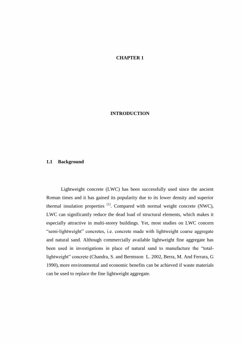
1.1 Background
Lightweight concrete (LWC) has been successfully used since the ancient
Roman times and it has gained its popularity due to its lower density and superior
thermal insulation properties [1]
. Compared with normal weight concrete (NWC),
LWC can significantly reduce the dead load of structural elements, which makes it
especially attractive in multi-storey buildings. Yet, most studies on LWC concern
“semi-lightweight” concretes, i.e. concrete made with lightweight coarse aggregate
and natural sand. Although commercially available lightweight fine aggregate has
been used in investigations in place of natural sand to manufacture the “total-
lightweight” concrete (Chandra, S. and Berntsson L. 2002, Berra, M. And Ferrara, G
1990), more environmental and economic benefits can be achieved if waste materials
can be used to replace the fine lightweight aggregate.

2
The use of lightweight concrete in reinforced concrete structures has several
advantages when compared with ordinary concrete or normal concrete such as
crossing of larger spans, high earthquake resistance, , heat conductivity property,
and fire strength etc. (Hüsem, 1995; Neville, 1975; Durmuş, 1988; Karaca, 1996)
[6,7]. Because of the advantages cited above lightweight concrete is being used in
many industrial countries. Although lightweight concrete has so many advantages
and superiorities over ordinary concrete, thus, the usage of this type of concrete is
not as common as ordinary concrete. The reasons for low usage of lightweight
concrete are the high prices of aggregates in countries whose lightweight aggregate
resources are poor, lack of experience, and knowledge of workers about lightweight
concrete (Karaca, 1996).
Lightweight concrete may also contain normal or lightweight, fine and/or
coarse aggregates. The rigid foam air cell system differs from conventional aggregate
concrete in the methods of production and in the more extensive range of end uses.
Lightweight concrete may be either cast-in-place or pre-cast. Lightweight concrete
mix designs in general are designed to create a product with a low density and
resultant relatively lower compressive strength (when compared to plain concrete)
(J.L.Clarke, 1993). When higher compressive strengths are required, the addition of
fine and/or course aggregate will result in a stronger lightweight concrete with
resultant higher densities. We should note that most lightweight concrete applications
call for a lightweight material. When considering the addition of course aggregate,
one must consider how appropriate this heavy aggregate will be to a project, which
typically calls for lightweight material. The inclusion of aerated aggregate,
particularly course aggregate may be counter-productive to the materials intended
performance (J.L.Clarke, 1993).

3
Structural lightweight concrete has an in-place density (unit weight) on the
order of 90 to 115 lb/ ft3
(1440 to 1840 kg/m3) compared to normal-weight concrete
with a density in the range of 140 to 150 lb/ ft (2240 to 2400 kg/m3). For structural
applications the concrete strength should be greater than 2500 psi (17.0 MPa). The
concrete mixture is made with a lightweight coarse aggregate or in some cases the
engineers can use a portion or the entire may be a lightweight product. Lightweight
aggregates used in structural lightweight concrete are naturally expanded shale, clay
or slate materials that have been fired in a rotary kiln to develop a porous structure.
Other products such as air-cooled blast furnace slag are also used. There are other
classes of non-structural lightweight concretes with lower density made with other
aggregate materials and higher air voids in the cement paste matrix, such as in
cellular concrete (AC1213R).
In this study, the aerated rock (Pumice) is the type of aggregate used, in order
to produce industrial building block with structural lightweight concrete forms.
Pumice (aerated aggregate) aggregate is a low density highly vesicular, volcanic
glass consisting mainly of silica SiO2. The high silica content (70% per g/100g)
positively affects the quality of pumice increasing the hardness of the material and its
resistance to chemical attack. Pumice Aggregate (aerated aggregate) is highly
recommended in lightweight concrete blocks either blended or as an all in pumice
mix. In cast stone as a lightweight backing mix and chimney flue liners. Lightweight
precast structures including IBS concrete block. In continuation, this project presents
the performance of aerated concrete aggregate which is used to produce structural
lightweight concrete block, in function to inspire the construction industries to use it
and design such structural IBS elements, for instance, the industry building system
(IBS) platform can use this type of light aggregate to make the IBS system with
satisfy and high structural compressive strength and low density which is less 20%-
25% than the use of conventional crashed aggregate.

4
1.2 Problem statements
There are many beneficial use of a structural lightweight concrete such as to
reduce the dead load of a concrete block, which then allows the structural designer to
produce a such size of IBS concrete block (with high strength and low density), to
reduce the size of block and other load bearing elements in case to let them to stand
up to carry the structure loads imposed upon them from various partitions of
structural load. However, structural lightweight concrete provides a more efficient
strength-to-weight ratio in structural elements. In most cases, the marginally higher
cost of the lightweight concrete is offset by size reduction of structural elements, less
reinforcing steel and reduced volume of concrete, resulting in lower overall cost, For
instance, in this study it has been planning to produce such samples of IBS block
with structural lightweight concrete mix design with Ordinary Portland cement
(OPC), a full replacement of conventional crashed aggregate by lightweight
aggregate (aerated aggregate) and to check the failure of the samples under flexural.
In continuation, some of the reasons of using aerated aggregate are to produce
lightweight concrete IBS interlocking wall block of size of 900mm in length, 700mm
in height and 200mm in width and wall rectangular beam with size is 2100mm in
length, 500mm in height and 200mm in width. These sizes are considered too
suitable to comply with RTD rule and placement on transport cargo. Due to this
successful function, it will lead to customer convincing attitude as they need to
provide not more transportation for assembly of the components due to the reduction
in weight is followed by savings in transport and greater ease of operation on the site;
there is less human fatigue and lead to faster speed of erection and hence to a
reduction of funding costs, also a powerful way to put new buildings to useful and
profitable employment as early as possible. In this study, the component is
divided into smaller transportable ‘lego’ sizes shaped block. The component
will be made into two or four cuts of component and analysis for best design
for assembly and disassembly with similar predecessor.

5
1.3 Objectives of research
The objectives of this research are:
1- To study the properties and behavior of aerated aggregate and use it as
structural lightweight concrete block-works aggregate on accordance to
BS1881: part 125-102 and BS 5328.
2- To investigate the flexural capacity of structural lightweight concrete of IBS
block-works and beam with a full replacement of conventional crashed
aggregate by aerated aggregate with Ordinary Portland cement (OPC).
3- To check the deflection, cracks, splitting strength, tensile strength and
ultimate compressive strengths of the IBS blocks and beam samples under
ultimate loads @ 28 days on accordance to BS1881: part 120 and compare
the results with a normal concrete in-fill.
1.4 Significance of study
The significance of this research and its findings will inspire the develop a
suitable mix design of lightweight concrete with aerated aggregate, in order to
produce a new approach of structural lightweight concrete block.
1- To develop a new potential technique to produce structural lightweight
concrete block, with an above average of structural compressive strength and
a lower density.
2- To produce a sample of structural lightweight concrete block with different
shape of IBS, in function to encourage the construction industry to made it as
a new approach for future use in IBS building and construction sectors.
3- To encourage of solving the problem of low and middle income earners to
purchase it.

6
1.5 Scope of study
The study was almost experimental in natural and it consists of three-phase
study scheme. First phase was focusing on the research of development based on the
existed studies and preparing the calculation of the structural lightweight mix design.
The second phase is preparing the reinforcements, the casting moulds and testing the
casted blocks @ 28days for the IBS blocks which are showing below in figure 1.1.
The third phase was concerning about the analysis and discussion of the results of
the IBS blocks samples.
The attempt of this study is to check the ultimate strength behavior of
IBS interlocking block system. The performance of this specimen will be estimated
through the capacity test. The crack at frame faces and its deflection will be
monitored during the test in order to get the expected results and fulfill the aims,
significant, objectives and scope of this study. The component consists of lightweight
infill’s that have been use for wall, and a frame which including beams and blocks.
The size of the IBS block is 800 mm × 700mm × 200mm and the size of the
IBS rectangular beam is 2100mm × 450mm × 200mm with length, height and width
respectively.
Figure 1.1: IBS lightweight concrete block
100
6 REFERENCES
Badir, Y., Kadir, M., and Hashim, A. (2002). ”Industrialized Building Systems
Construction in Malaysia” J. Archit. Eng., 8(1), 19–23.doi: 10.1061/
(ASCE),1076-0431(2002)8:1(19).
Berra, M. And Ferrara, G, (1990). “Normal Weight and Total-Lightweight High-
Strength Concretes”: A Comparative Experimental Study”, Noyes
Publications.
Chandra, S. And Berntsson, L, (2002). “Lightweight Aggregate Concrete, Science,
Technology and Applications”. Noyes Publications. William Andrew.
Dr J. L. Clarke, (1993). “Structural Lightweight Aggregate Concrete”, Blackie
Academic & Professional, an Imprint of Chapman & Hall Wester Cleddens
Road, Bishopbrigges, Glasgow G64 2NZ.
Harun Tanyildizi, Ahmet Coskun, (2008). “Performance of lightweight concrete with
silica fume after high temperature”, Construction and Building Materials,
Firat University, Turkey, October 2008.
Kayali, O.A. and Haque, M.N, (1997). “A New Generation of Structural Lightweight
Concrete” ACI, China, Water and Electricity, Publishing House.

101
Karaca Z, (1996). “Investigation of Behavior of Lightweight and Ordinary
Reinforced Concrete Beams With Deformed Bars By Comparing With Each
Other In The Light Of Synthesis Work”, Ms Thesis, Karadeniz Technical
University, Trabzon, Turkey.
Legatski LA, (2006). “Cellular concrete, significance of tests and proper-ties of
concrete and concrete making materials”. In: Klieger PK,Lamond JF, editors.
ASTM Special Technical Publication.Philadelphia, No. 169C. p. 533-9
McSaveney, L.G. (2000) The Wellington stadium: “New Zealand's first use of high
Strength lightweight precast concrete, in Second international symposium on
structural lightweight aggregate concrete”. Helli Grafisk, Oslo, Norvege:
Kristiansand.
Mohd Roji Samidi, (1997). “First report research project on lightweight Concrete”
Universiti Teknologi Malaysia, Skudai, Johor Bahru.
Shan Somayuji (1995), “Civil Engineering Materials”, N.J Prentice Hall Inc, USA,
3rd Edition, Englewood Cliff.
S.A. Khedr, M.N. Abou-Zeid, (1994). “Characteristics of silica-fume concrete”, J.
Mater. Civil Engineering. ASCE.
S. Aroni, G. J. de Groot (Editor), M. J. Robinson, (1993). “Autoclaved aerated
concrete -Properties, testing and design”, London; New York: E &FN Spon.
Valore, R.C., (1954). “Cellular Concrete Composition and Methods of Preparation
and Celluler Concrete-Physical Properties”. J Am concrt Inst. 25, pp. 773-
95.