UNIVERSITI PUTRA MALAYSIA IMPROVEMENTS IN …psasir.upm.edu.my/11178/1/FK_2001_61_A.pdf ·...
25
UNIVERSITI PUTRA MALAYSIA IMPROVEMENTS IN DESIGN OF LOCAL FLUORESCENT ELECTRONIC BALLASTS IN COMPLIANCE WITH THE RELATED LOCAL AND INTERNATIONAL STANDARDS ZULKEFLI BIN YAACOB FK 2001 61
Transcript of UNIVERSITI PUTRA MALAYSIA IMPROVEMENTS IN …psasir.upm.edu.my/11178/1/FK_2001_61_A.pdf ·...
UNIVERSITI PUTRA MALAYSIA
IMPROVEMENTS IN DESIGN OF LOCAL FLUORESCENT ELECTRONIC BALLASTS IN COMPLIANCE WITH THE RELATED
LOCAL AND INTERNATIONAL STANDARDS
ZULKEFLI BIN YAACOB
FK 2001 61
IMPROVEMENTS IN DESIGN OF LOCAL FLUORESCENT ELECTRONIC BALLASTS IN COMPLIANCE WITH THE RELATED
LOCAL AND INTERNATIONAL STANDARDS
By
ZULKEFLI BIN Y AACOB
Thesis Submitted in Fulfilment of the Requirement for the Degree of Master of Science in the Faculty of Engineering
Universiti Putra Malaysia
February 2001
Abstract of thesis presented to the Senate of Universiti Putra Malaysia in fulfilment of the requirement of the degree of Master of Science.
IMPROVEMENTS IN DESIGN OF LOCAL FLUORESCENT ELECTRONIC BALLASTS IN COMPLIANCE WITH THE RELATED
LOCAL AND INTERNATIONAL STANDARDS
By
ZULKEFLI BIN Y AACOB
February 2001
Chairman: Ir. Dr. Md. Yusof Ismail
FaCUlty: Engineering
The fluorescent electronic ballast has been in the market for a long time but has not
created any great impact in the illumination industry due to its high initial cost of
investment compared to the conventional magnetic ballast. With the advancement
in power electronics and utilization of power semiconductor which is available
commercially today, it is now possible to implement almost every type of desired
conversion of current, voltage or frequency and availability of electronic
components with higher power ratings. Thus, it is now possible to manufacture an
economically priced, light weight, lower watt-loss and high quality with maximum
performance electronic ballast which is compatible with all types of fluorescent
luminaries.
11
This study is undertaken to improve the design of existing locally manufactured
electronic ballasts. The study indicated that many of these commercial electronic
ballasts only have partial or minimum compliance requirements or none at all to the
related local and international standards, namely MS IEC 928, MS IEC 929 and
EMC requirements as stipulated by SIRIM Berhad. From a survey on nine
different ballast manufacturers, only seven manufacturers conducted two tests on
MS IEC 928 and MS IEC 929 and only two manufacturers conducted a complete
list of tests to ascertain whether their product comply with the related local and
international standards. Since electronic ballast is listed as one of the electrical
controlled items by the Department of Electricity and Gas Supply of Malaysia
(DEGSM), it is crucial that the EMC test be imposed prior to ballast approval.
A directive was issued by the Malaysian government on the 3rd of July 1998 to
implement energy conservation and to promote the use of energy efficient
equipment specifically on lighting luminaries and lighting control systems.
DEGSM noted the limitations of fluorescent ballast watt-loss hence, this study is
undertaken to meet the implementation of energy conservation regulations/act in
the near future.
The study discussed the advantages and disadvantages of electronic ballasts, their
operation and performance characteristics and problems encountered during their
normal operations, for instance, surges, starting current, power factor, watt-loss.
11l
ambient temperature and environmental effects, lamp/ballast premature failures,
harmonics and electromagnetic (EM) disturbances, efficiency and dimming.
VariOllS samples of electronic ballast were collected and tested for compliances
with local and international standards. It was found that many samples failed the
tests on total harmonic distortion (THD) which exceeded the 25% limit.
From the test data collected on the study, the findings from the analysis on the
operation, performance, design and construction of the typical electronic ballast
were utilised in the construction of two improved versions of electronic ballast
prototypes. The two improved versions were retested and both passed all the tests
conducted on them with better results.
I\"
Abstrak tesis yang dikemukakan kepada Senat Universiti Putra Malaysia sebagai memenuhi keperluan untuk ijazah Master Sains.
PEMBAIKAN DALAM REKA BENTUK BALLAST ELEKTRONIK PENDAFLUOR TEMPATAN DI DALAM MEMENUHI PIA W AI-PIA W AI
TEMPATAN DAN ANTARABANGSA YANG BERKAITAN
Oleh
ZULKEFLI BIN Y AACOB
Februari 2001
Pengerusi: Ir. Dr. Md. Yusof Ismail
Fakulti: Kejuruteraan
Ballast elektronik bagi kelengkapan lampu pendafluor telah lama berada di dalam
pasaran tetapi tidak dapat memberi sebarang impak yang ketara di dalam industri
pencahayaan disebabkan oleh kos pelaburan awal yang agak tinggi jika
dibandingkan dengan ballast konvensional jenis magnetik. Dengan kemajuan di
dalam bidang elektronik kuasa dan penggunaan semikonduktor kuasa secara
kommersil yang terdapat sekarang ini, ianya berupaya untuk melaksanakan hampir
setiap jenis penukaran yang diinginkan bagi arus, voltan atau frekuensi dan
kedapatannya komponen-komponen elektronik yang berkadaran kuasa tinggi.
Maka dengan itu, buat masa ini, adalah berkemungkinan besar untuk menghasilkan
ballast elektronik pada kos yang lebih ekonomik, ring an, berkehilangan watt rendah
dan berkualiti tinggi pada pedaksanaan yang maksima bersesuaian dengan semua
jenis kelengkapan lampu pendafluor.
v
Kajian ini adalah bertujuan untuk memperbaiki reka bentuk bagi ballast elektronik
buatan tempatan sedia ada. Kajian menunjukkan bahawa kebanyakan ballast
elektronik kommersil tidak mempunyai, hanya mempunyai sebahagian atau
pematuhan minima ke atas keperluan berdasarkan piawai-piawai tempatan dan
antarabangsa berkaitan saperti MS IEC 928, MS lEC 929 dan keperluan bagi
kesesuaian elektromagnetik (EMC) sapertimana yang diperlukan oleh SIRIM
Berhad. Daripada kajian yang telah dibuat ke atas 17 contoh yang dikumpulkan
daripada sembilan pengeluar ballast elektronik yang berlainan, hanya tujuh
pengeluar telah melakukan dua ujian bagi MS IEC 928 dan MS IEC 929 dan hanya
dua pengeluar sahaja telah melakukan senarai lengkap ujian. Ini adalah penting
kerana ballast elektronik adalah merupakan salah satu daripada barangan e1ektrik
terkawal oleh Jabatan Bekalan Elektrik dan Gas Malaysia (JBEGM).
Kajian ini juga membincangkan tentang kebaikan dan keburukan tentang ballast
elektronik, ciri-ciri operasi dan perlaksanaan dan juga masalah-masalah yang
dihadapi semasa ianya beroperasi secara normal saperti penerpaan, arus mula,
faktor kuasa, kehilangan watt, suhu sekeliling dan kesan keatas alam sekitar,
kegagalan pra-matang bagi lampulballast, harmonik dan kesan gangguan
elektromagnetik (EM), kecekapan dan pemalapan.
Pelbagai contoh ballast elektronik telah dikumpulkan dan diuji-kaji bagi
memastikan pematuhan berdasarkan kepada keperluan dan telah didapati bahawa
kebanyakan contoh yang diuji telah gagal bagi ujian "Jumlah Herotan Harmonik"
vi
yang mana melebihi tahap 25%. Daripada data ujian yang dikumpulkan di atas
kajian yang telah dibuat, analisa ke atas operasi, perlaksanaan, reka bentuk dan
pembinaan bagi ballast biasa telah digunakan di dalarn pembinaan dua versi contoh
sulung ballast elektronik yang telah diperbaiki. Ianya telah diuji sebagaimana yang
telah dilakukan keatas contoh-contoh yang telah dikumpulkan di mana kedua
duanya telah didapati lulus kesemua ujian berkenaan dengan contoh sulung yang
kedua telah memberikan keputusan yang lebih baik.
Pada bahagian akhir kajian, data-data telah terkumpul telah dijadualkan untuk
perbincangan dan perbandingan secara keseluruhan dalarn menentukan sarna ada
contoh-contoh dan contoh sulung tersebut telah dapat memenuhi keperluan piawai
piawai berkenaan secara sepenuhnya atau tidak. Kesimpulan ke atas kaj ian
kemudiannya telah dibuat. Penyelidikan lanjut dan perakuan telah dicadangkan
berdasarkan kepada pendekatan reka bentuk bam, topologi-topologi dan teknik
teknik bagi pembinaan ballast elektronik dengan merujuk kepada penyelidikan
yang dijalankan oleh berbagai pereka ballast elektronik.
Vll
ACKNOWLEDGEMENTS
A great effort went into the writing-up of this thesis which has been a great
experience and an enrichment of knowledge. I would like to thank the following
people and organisations for their contributions, without which this thesis could
never have been completed.
First and always, my family. My ever-patient and supportive wife and two
daughters, who have made many sacrifices during the duration and understood my
need to further my studies. Thank you for your sincere emotional support, patience
and understanding.
Thank you also to Ir. Dr. Md. Yusof Ismail, my supervisor and co-supervisors, Ir.
Dr. Norman Mariun, Dr. Megat Hamdan Megat Ahmad and Dr. Mohd. Sapuan
Salit for their tireless effort, guidance and generous recommendations and insights
throughout the process of the writing-up of the thesis.
Thank you also to the electronic ballast manufacturers for their cooperation in
allowing me to utilise their available technical resources and testing facilities
during the research and for the analysis conducted on the thesis.
Vlll
I certify that an Examination Committee met on 6th Februari 2001 to conduct the final examination of Zulkefli Yaacob on his Master of Science thesis entitled "Improvements in Design of Local Fluorescent Electronic Ballasts in Compliance with Related Local and International Standards" in accordance with the Universiti Pertanian Malaysia (higher Degree) Act 1980 and Universiti Pertanian Malaysia (Higher Degree) Regulations 1981. The Committee recommends that the candidate be awarded the relevant degree. Members of the Examination Committee are as follows:
SHAMSUDDIN SULAIMAN, Ph. D., Associate Professor, Faculty of Engineering Universiti Putra Malaysia (Chairman)
MD.YUSOF ISMAIL , Ph. D., P.Eng., Associate Professor, Faculty of Engineering Universiti Putra Malaysia (Member)
NORMAN MARIUN, Ph. D., P.Eng., Associate Professor, Faculty of Engineering Universiti Putra Malaysia (Member)
MEGAT MOHAMAD HAMDAN MEGAT AHMAD, Ph. D., Faculty of Engineering Universiti Putra Malaysia (Member)
MOHD. SAPUAN SALIT, Ph. D., Faculty of Engineering Universiti Putra Malaysia (Member)
Q �-----------------------------
MOH . G MALI MOHA YIDIN, Ph. D., ProfessoilDeputy Dean of Graduate School, Universiti Putra Malaysia.
Date:
IX
This thesis submitted to the Senate of Universiti Putra Malaysia was accepted as fulfilment of the requirement for the degree of Master of Science.
x
HAZALI MOHA YIDIN, Ph.D.
Professor Deputy Dean of Graduate School Universiti Putra Malaysia
Date:
DECLARATION
I hereby declare that the thesis is based on my original work except for quotations and citations which have been duly acknowledged. I also declare that it has not been previously or concurrently submitted for any other degree at UPM or other institutions.
Xl
Name: ZULKEFLI BIN Y AACOB
Date: 1. fl/ '2{ too I
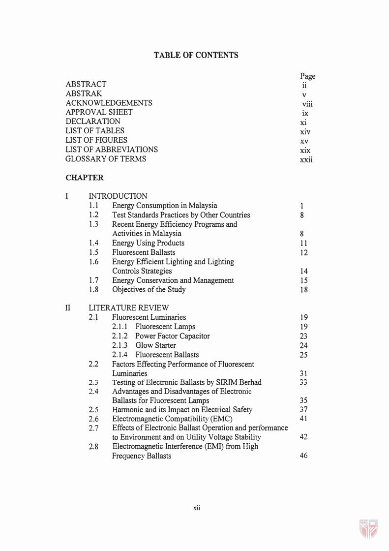
TABLE OF CONTENTS
Page ABSTRACT 11 ABSTRAK v ACKNOWLEDGEMENTS Vlll APPROVAL SHEET ix DECLARATION Xl LIST OF TABLES XIV LIST OF FIGURES xv LIST OF ABBREVIATIONS XIX GLOSSARY OF TERMS XXll
CHAPTER
I INTRODUCTION 1 . 1 Energy Consumption in Malaysia 1 1 .2 Test Standards Practices by Other Countries 8 1 .3 Recent Energy Efficiency Programs and
Activities in Malaysia 8 1.4 Energy Using Products 1 1 1.5 Fluorescent Ballasts 1 2 1 .6 Energy Efficient Lighting and Lighting
Controls Strategies 1 4 1 .7 Energy Conservation and Management 1 5 1 .8 Objectives of the Study 1 8
II LITERATURE REVIEW 2.1 Fluorescent Luminaries 1 9
2. 1 . 1 Fluorescent Lamps 1 9 2. 1.2 Power Factor Capacitor 23 2. 1 .3 Glow Starter 24 2. 1.4 Fluorescent Ballasts 25
2.2 Factors Effecting Performance of Fluorescent Luminaries 31
2.3 Testing of Electronic Ballasts by SIRlM Berhad 33 2.4 Advantages and Disadvantages of Electronic
Ballasts for Fluorescent Lamps 35 2.5 Harmonic and its Impact on Electrical Safety 37 2.6 Electromagnetic Compatibility (EMC) 41 2.7 Effects of Electronic Ballast Operation and performance
to Envirorunent and on Utility Voltage Stability 42 2.8 Electromagnetic Interference (EMI) from High
Frequency Ballasts 46
XII
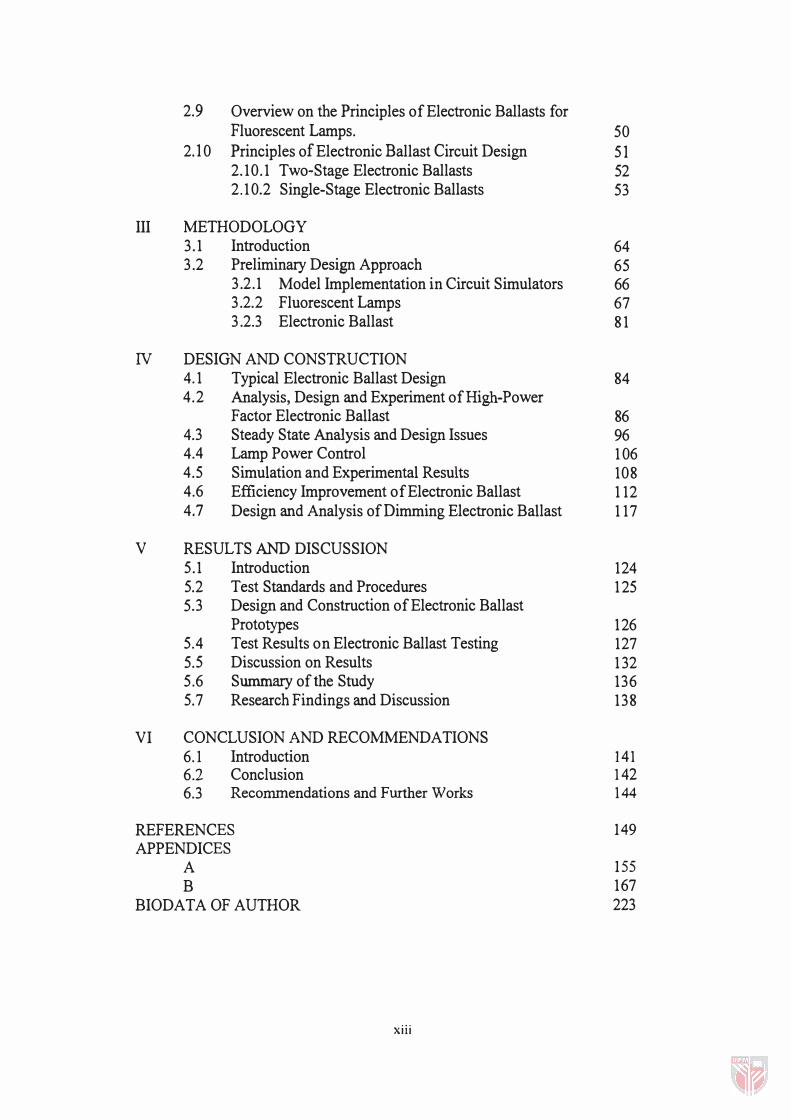
2.9 Overview on the Principles of Electronic Ballasts for Fluorescent Lamps. 50
2.10 Principles of Electronic Ballast Circuit Design 51 2.10.1 Two-Stage Electronic Ballasts 52 2.1 0.2 Single-Stage Electronic Ballasts 53
III METHODOLOGY 3.1 Introduction 64 3.2 Preliminary Design Approach 65
3.2.1 Model Implementation in Circuit Simulators 66 3.2.2 Fluorescent Lamps 67 3 .2.3 Electronic Ballast 8 1
IV DESIGN AND CONSTRUCTION 4. 1 Typical Electronic Ballast Design 84 4.2 Analysis, Design and Experiment of High-Power
Factor Electronic Ballast 86 4.3 Steady State Analysis and Design Issues 96 4.4 Lamp Power Control 1 06 4.5 Simulation and Experimental Results 108 4.6 Efficiency Improvement of Electronic Ballast 1 12 4.7 Design and Analysis of Dimming Electronic Ballast 1 17
V RESULTS AND DISCUSSION 5.1 Introduction 124 5.2 Test Standards and Procedures 1 25 5.3 Design and Construction of Electronic Ballast
Prototypes 126 5.4 Test Results on Electronic Ballast Testing 127 5.5 Discussion on Results 1 32 5 .6 Summary of the Study 136 5.7 Research Findings and Discussion 138
VI CONCLUSION AND RECOMMENDATIONS 6.1 Introduction 141 6.2 Conclusion 1 42 6.3 Recommendations and Further Works 1 44
REFERENCES 149 APPENDICES
A 155 B 167
BIODATA OF AUTHOR 223
xiii
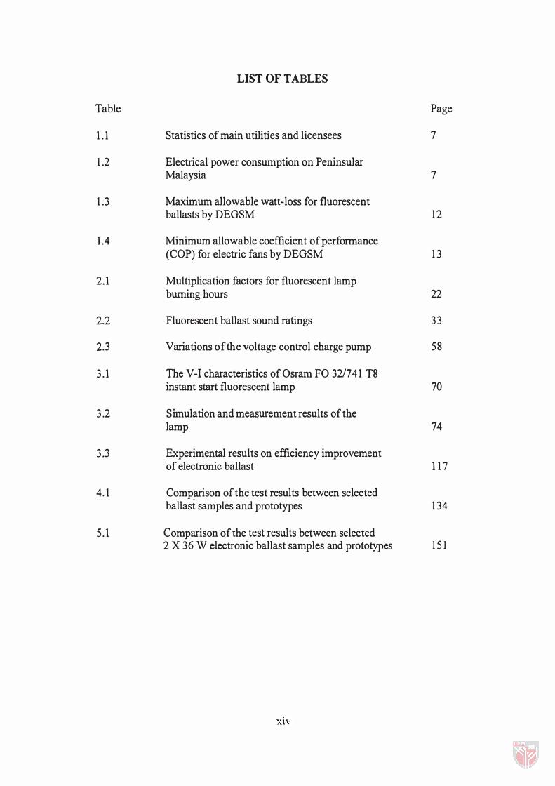
LIST OF TABLES
Table Page
1 .1 Statistics of main utilities and licensees 7
1 .2 Electrical power consumption on Peninsular Malaysia 7
1 .3 Maximum allowable watt-loss for fluorescent ballasts by DEGSM 12
1 .4 Minimum allowable coefficient of performance (COP) for electric fans by DEGSM 1 3
2.1 Multiplication factors for fluorescent lamp burning hours 22
2.2 Fluorescent ballast sound ratings 33
2.3 Variations of the voltage control charge pump 58
3 . 1 The V-I characteristics of Os ram FO 321741 18 instant start fluorescent lamp 70
3 .2 Simulation and measurement results of the lamp 74
3.3 Experimental results on efficiency improvement of electronic ballast 1 1 7
4.1 Comp�son of the test results between selected ballast samples and prototypes 1 34
5.l Comparison of the test results between selected 2 X 36 W electronic ballast samples and prototypes 1 51
XIV
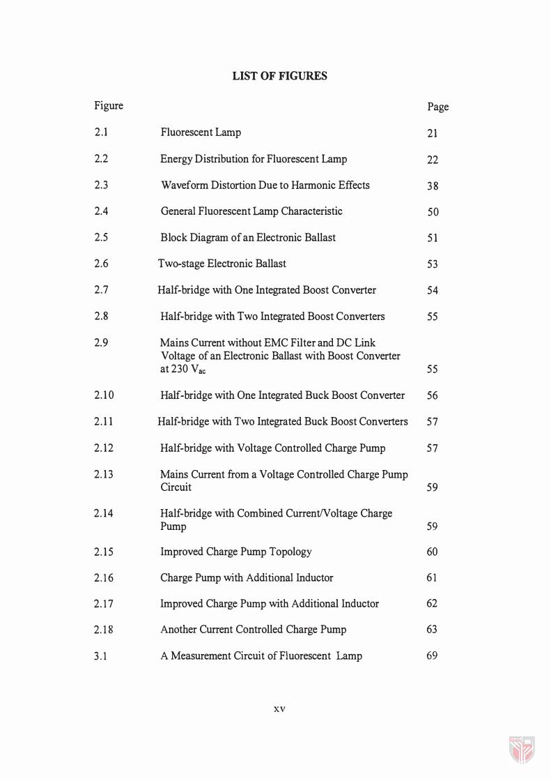
LIST OF FIGURES
Figure Page
2 . 1 Fluorescent Lamp 21
2.2 Energy Distribution for Fluorescent Lamp 22
2.3 Waveform Distortion Due to Harmonic Effects 3 8
2.4 General Fluorescent Lamp Characteristic 50
2.5 Block Diagram of an Electronic Ballast 5 1
2.6 Two·stage Electronic Ballast 53
2.7 Half·bridge with One Integrated Boost Converter 54
2.8 Half-bridge with Two Integrated Boost Converters 55
2.9 Mains Current without EMC Filter and DC Link Voltage of an Electronic Ballast with Boost Converter at 230 Vac 55
2. 1 0 Half·bridge with One Integrated Buck Boost Converter 56
2 . 1 1 Half-bridge with Two Integrated Buck Boost Converters 57
2. 12 Half·bridge with Voltage Controlled Charge Pump 57
2.1 3 Mains Current from a Voltage Controlled Charge Pump Circuit 59
2. 14 Half·bridge with Combined CurrentIV oltage Charge Pump 59
2. 1 5 Improved Charge Pump Topology 60
2.1 6 Charge Pump with Additional Inductor 6 1
2. 1 7 Improved Charge Pump with Additional Inductor 62
2.18 Another Current Controlled Charge Pump 63
3 . 1 A Measurement Circuit of Fluorescent Lamp 69
xv
3.2 V-I Characteristics Plot of Os ram FO 32W1741 TS Instant Start Fluorescent Lamp 70
3.3 The Proposed PSpice Circuit for the Lamp Model 73
3.4 A Circuit for Testing the Proposed Lamp Model 73
3.S(a) The Negative Dynamic Resistance Characteristics of the Lamp Obtained from Simulation 75
3.5(b) The Negative Dynamic Resistance Characteristics of the Lamp Obtained from Experiment 75
3.6 A Simplified Schematic of the Half-bridge Resonant Ballast 76
3.7 The Plot of the Normalised Current Versus Operating Frequency with Various Zo(o) and V H(o) as Parameters 78
3.S(a), (c) The Simulation Results of the System 80
3.8(b), (d) The Experimental Results of the System 80
3.9 The Typical Ballast Circuit 82
3.10 Comparison of Power Input 83
3.11 Comparison of Light Output 83
4.1 The PF Correction Converter Block Diagram 88
4.2 The Required Output Characteristics of Box to Achieve PF Correction 88
4.3 High Power Factor ACIDC Converter 89
4.4 Characteristics of a Series Resonance Converter 89
4.5 High PF Correction ACIDC Converter 90
4.6 The Basic Charge Pump PF Correction ACIDC Converter 90
4.7 VS-CPPFC Electronic Ballast 91
XVI
4.8 The Simplified VS-CPPFC Converter 91
4.9 Switched Waveform of Figure 3.19 92
4.10 CPPFC Electronic Ballast 96
4.11 Equivalent Circuit of Figure 3.21 97
4.12 Eight Topological Stages 98
4.13 Key Waveforms of the Electronic Ballast 99
4.14 Symmetrical CPPFC Electronic Ballast 105
4.15 The Lamp Power Control Diagram 108
4.16 DC Bus Voltage Across the Bulk Capacitor, CB During Preheat and Start-up Modes 109
4.17 The Simulated Switching Waveforms 110
4.18 The Experimental Switching Waveforms 110
4.19 The Measured Input Line Current Waveforms 111
4.20 The Measured Switching Waveforms of the Symmetrical CPPFC Electronic Ballast 111
4.21 Half-bridge Inverter Circuit Configuration 113
4.22 The Block Diagram of the Improved Efficiency Electronic Ballast 116
4.23 The Power Circuit for Dimming Electronic Ballast 119
4.24 Half-bridge Inverter Output Waveforms at 0)5>(00 120
5 .1 The Block Diagram of Electronic Ballast Prototype No.1 127
5.2 The Block Diagram of Electronic Ballast Prototype No.2 127
XVll
5.3 The Schematic Diagram of Electronic Ballast Prototype No.1 128
5.4 The Schematic Diagram of Electronic Ballast Prototype No. 2 129
5.5 Photograph of Electronic Ballast Prototype No. 1 130
5.6 Photograph of Electronic Ballast Prototype No. 2 130
6.l CIC-CPPFC Conceptual Circuit 145
6.2 CIC-CPPFC Electronic Ballast 145
6.3 CIC-CPPFC Converter Diagram and its Waveforms 146
XVlll
LIST OF ABBREVIATIONS
AC
ANN ANSI
BSI
CBM
CCF
CENELEC
CFL
CIC
CISPR
CO
CO2
COP
CPPFC
CS
dB
DC
DCM
DEGSM
DSM
ECM
EEO
EM
EMC
EMF
EMI
ESD
ESR
EUT
Alternating Current
Artificial Neural Network
American National Standards Institute
British Standard Institute
Certified Ballast Manufacturers Association
Current Crest Factor
European Committee for Electrotechnical Standardisation
Compact Fluorescent Lamp
Continuous Input Current
International Special Committee on Radio Interference
Carbon Monoxide
Carbon Dioxide
Coefficient of Performance
Charge Pump Power Factor Correction
Current Source
Decibles
Direct Current
Discontinuous Current Mode
The Department of Electricity and Gas Supply of Malaysia
Demand Side Management
Energy Centre of Malaysia (pusat Tenaga Malaysia)
Energy Efficiency Officer
Electromagnetic
Electromagnetic Compatibility
Electromotive Force
Electromagnetic Interference
Electrostatic Discharge
Equivalent Series Resistance
Equipment Under Test
xix
FCC
FLEB
GDP
GTO
HVAC
HF
HID HPS
HVDC
IC
IEC
IEEE
IES
IGBT
IPP
ISO
KPBE
LISN
LLS
LPW
MOSFET
MS
NEC
NEMA
NLPIP
NTC
PCB
PF
PFC
PLC
Federal Communications Commission
Fluorescent Lamp with Electronic Ballast
Gross Domestic Product
Gate Turn-off
Heating, Ventilating and Air-conditioning
High Frequency
High Intensity Discharge
High Pressure Sodium
High Voltage Direct Current
Integrated Circuit
International Electrotechnical Commission
Institution of Electrical and Electronics Engineers
llluminating Engineers Society
Insulated Gate Bipolar Transistor
Independent Power Producer
International Organisation for Standardisation
Ketua Pengarah Bekalan Elektrik (Director General of Electricity
Supply)
Line Impedance Simulation Network
Lembaga Letrik Sabah (Sabah Electricity Board)
Lumen per Watt
Metal Oxide Semiconductor Field Effect Transistor
Malaysian Standard
National Electrical Code
National Electrical Manufacturers Association
National Lighting Product Information Program
Negative Temperature Coefficient
Printed Circuit Board
Power Factor
Power Factor Correction
Power Line Carrier
xx
PSpice
PWD
PWM
RCCB
RF
RFI
RLO
RMS
SCR
SESCO
SIRIM
S02
SPICE
SLICE
THD
TNB UDCS
UL
UPS
US FDA
UVLO
VCO
VDC
VS
A member of SPICE family of Circuit Simulators
Public Works Department
Pulse Width Modulation
Residual Current Circuit Breaker
Radio Frequency
Radio Frequency Interference
Relative Light Output
Root Mean Square
Silicon Control Rectifier
Sarawak Electricity Supply Corporation
Standards and Industrial Research Institute of Malaysia
Sulphur Dioxide
Simulation Program with Integrated Circuit Emphasis
Circuit simulator program developed by Harris Semiconductor
Total Harmonic Distortion
Tenaga Nasional Berhad
User Defined Controlled Source
Underwriters Laboratories of USA
Uninterruptible Power Supply
Food and Drug Administration of USA
Under-voltage Lockout
Voltage Cut-out
DC Voltage Source
Voltage Source
xxi
GLOSSARY OF TERMS
The following technical and lighting terminologies are frequently used with reference to the study. These are presented in alphabetical order and explained so that they are easy to understand. For a complete range of lighting terminology and precise defInitions, please refer to the IES Lighting Handbook, 1981.
Active Filter
Advance, Firing Angle
Ambient temperature
Asymmetrical
Avalanche
Avalanche Diode
A filter which is switched in response to demand to
attenuate or eliminate harmonic components and
compensate for active power.
The angle at which a thyristor starts conduction in
advance of, and relative to, the instant when the
thyristor forward voltage falls to zero in a converter.
Used in relation to the inverting mode of operation.
The temperature of the general mass of air or cooling
medium into which heat is finally transferred from a
hot body.
Not uniform in characteristic or construction.
A chain reaction which occurs when minority carriers
are accelerated by a high electric field, so liberating
further carriers leading to a sharp increase in reverse
current and breakdown.
A diode which may temporarily be exposed to
voltages of the order of the breakdown voltage.
XXll
Ballast
Ballast Factor
Bidirectional
Breakdown Voltage
Bridge
Chopping
Clamping Voltage
Closed-loop
Colour Rendering
Commutating Diode
A device used with gaseous discharge lamps that
provides necessary conditions to start and operate the
lamps.
The percentage of light produced by a commercial
ballast compared to a reference or standard ballast.
Capable of current conduction in both directions, for
example a triac.
The reverse voltage level at which the reverse current
increases rapidly in a diode.
Full-wave converter.
A technique of rapidly switching on and off a source
of voltage.
Introduction of a voltage reference level to a pulsed
or transient waveform to limit the peak value.
A system in which information regarding the state of
a controlled quantity is fed back to the controlling
element.
An expression for the effect of a light source on the
colour appearance of objects in comparison with their
colour appearance under a reference light source.
A diode placed across a DC load to permit transfer of
load current away from the source, and so allow the
xxiii
Conducting Angle
Conduction Loss
Constant-current Inverter
Constant-voltage Inverter
Converter
Critical Damping
Damping
D.C Link
Delay, Firing Angle
thyristors in the DC source to turn off. In addition to
permitting commutation of the source thyristors, the
diode will prevent reversal of the load voltage.
The angle over which a device conducts.
The energy dissipated within the device during the
on-state conduction.
An inverter fed from a DC source with a large series
inductor, so that over each inverter cycle the source
current remains almost constant.
An inverter fed from a DC source with a large
parallel capacitor, so that over each inverter cycle the
source voltage remains almost constant.
A circuit which convert AC to DC or vise versa.
Damping which gives most rapid transient response
without overshoot or oscillation.
Extraction of energy from an oscillating system.
Intermediate DC stage between two systems of
different frequency.
The retarded angle at which a thyristor starts
conducting relative to that instant when the thyristor
xxiv