UNIVERSITI PUTRA MALAYSIA PERFORMANCE …psasir.upm.edu.my/6069/1/FK_2005_53(1-24).pdf · PSB boleh...
25
UNIVERSITI PUTRA MALAYSIA PERFORMANCE STUDIES OF STATIC SYNCHRONOUS COMPENSATOR AND STATIC SYNCHRONOUS SERIES COMPENSATOR MODES FOR CONVERTIBLE STATIC COMPENSATOR WAHIDAH BINTI ABD HALIM. FK 2005 53
Transcript of UNIVERSITI PUTRA MALAYSIA PERFORMANCE …psasir.upm.edu.my/6069/1/FK_2005_53(1-24).pdf · PSB boleh...
UNIVERSITI PUTRA MALAYSIA
PERFORMANCE STUDIES OF STATIC SYNCHRONOUS COMPENSATOR AND STATIC SYNCHRONOUS SERIES COMPENSATOR MODES FOR CONVERTIBLE STATIC
COMPENSATOR
WAHIDAH BINTI ABD HALIM.
FK 2005 53
PERFORMANCE STUDIES OF STATIC SYNCHRONOUS COMPENSATOR AND STATIC SYNCHRONOUS SERIES COMPENSATOR MODES FOR
CONVERTIBLE STATIC COMPENSATOR
WAHIDAH BINTI ABD HALIM
Thesis Submitted to the School of Graduate Studies, Universiti Putra Malaysia, in Fulfilment of the Requirements for the Degree of Master of Science
May 2005
Dedicated to my beloved husband Ishak;
my parents, sisters, and in-laws for giving a constant source of support and encouragement.
Abstract of thesis presented to the Senate of Universiti Putra Malaysia in fulfilment of the requirements for the degree of Master of Science
PERFORMANCE STUDIES OF STATIC SYNCHRONOUS COMPENSATOR AND STATIC SYNCHRONOUS SERIES COMPENSATOR MODES FOR
CONVERTIBLE STATIC COMPENSATOR
BY
WAHIDAH BINTI ABD HALIM
May 2005
Chairman: Associate Professor Norman Mariun, PhD
Faculty: Engineering
This thesis presents an overview of the emerging Flexible AC Transmission System
(FACTS) and Convertible Static Compensator (CSC) technologies. CSC, the flexible
multifunctional compensator is an innovation fi-om FACTS technology. These
technologies are fully utilized the existing transmission system assets, that improve
transmission hctionality for economical and environmental reasons.
The CSC can occupy as shunt and/or series compensation devices providing various
modes. The CSC can operate in 11 different configurations depending on control
objectives, for voltage control at bus system as well as power flow control on two
existing transmission lines. The CSC can function as a Static Synchronous
Compensator (STATCOM), Static Synchronous Series Compensator (SSSC),
Unified Power Flow Controller (UPFC) and Interline Power Flow Controller (IPFC).
This research work focused on STATCOM and SSSC for CSC as shunt and series
controller, respectively. The basic operation of the controllers is explained, together
with the circuit configurations and general control strategies. The STATCOM and
SSSC are based on a voltage-sourced converter (VSC) which consist of Gate Turn-
Off (GTO) Thyristor as the switching devices, are used in this research work to study
the performance of the controllers.
An 11-bus system as the test system is used throughout the study to verifL the
proposed models and its control strategies. The model of the controllers and its
control are then validated through PSCAD/EMTDC simulation. Steady-state analysis
is done to demonstrate the capability of the controllers designed for improving
voltage regulation and power flows in the transmission systems. The result obtained
from the simulations clearly showed that the designed STATCOM and SSSC
controllers are capable in regulating voltage and increased the transmitting power.
Abstrak tesis yang dikemukakan kepada Senat Universiti Putra Malaysia sebagai memenuhi keperluan untuk ijazah Master Sains
KAJIAN PRESTASI MOD PEMAMPAS SEGERAK STATIK DAN PEMAMPAS SIR1 SEGERAK STATIK UNTUK PEMAMPAS
STATIK BOLEHUBAH
Oleh
WAHIDAH BINTI ABD HALIM
Mei 2005
Pengerusi: Profesor Madya Norman Mariun, PhD
Fakulti: Kejuruteraan
Tesis ini membentanglcan keseluruhan mengenai perkembangan teknologi Sistem
Penghantaran Arus Ulang-Alik Fleksibel (SPAUF) dan Pemampas Statik Bolehubah
(PSB). PSB, pemampas fleksibel yang mempunyai pelbagai h g s i merupakan satu
inovasi daripada teknologi SPAUF. Teknologi ini mengeksploitasikan sepenuhnya
aset sistem penghantaran sedia ada, untuk memperbaiki h g s i penghantaran
disebabkan faktor ekonomi dan dam sekitar.
PSB boleh digunakan sebagai alat pemampas secara selari dda tau siri yang
membenarkan pelbagai mod. PSB boleh beroperasi dalam 11 konfigurasi berlainan
bergantung k epada t ujuan k awalan, b agi k awalan v oltan p ada s istem b as d an j uga
kawalan aliran kuasa pada dua talian penghantaran sedia ada. PSB boleh b e h g s i
sebagai Pemampas Segerak Statik (PSS), Pemampas Siri Segerak Statik (PSSS),
Gabungan Pengawal Aliran Kuasa (GPAK) dan Pengawal Aliran Kuasa Antara-
talian (PAKA).
Kajian penyelidikan ini memfokuskan kepada PSS dan PSSS dalam PSB sebagai
pengawal selari dan sesiri. Asas operasi bagi pengawal-pengawal tersebut
diterangkan bersama dengan tatarajah litar dan strategi kawalan. PSS dan PSSS
berasaskan penukar bekalan voltan yang mengandungi Gate Turn-Off (GTO)
Thyristor sebagai alat pensuisan, digunakan di dalam kajian ini untuk mengkaji
prestasi pengawal-pengawal tersebut.
Sistem I I-bas digunakan sistem kajian pada keseluruhan tesis untuk mengesahkan
model yang dicadangkan dan strategi kawalannya. Model pengawal dan strategi
kawalannya disahkan melalui simulasi PSCAD/EMTDC. Analisis keadaan mantap
dilakukan bagi mendemontrasi keupayaan pengawal-pengawal tersebut yang direka
untuk memperbaiki pengaturan voltan dan aliran kuasa dalarn sistem penghantaran.
Keputusan yang diperolehi daripada simulasi yang dijalankan menunjukkan bahawa
pengawal PSS dan PSSS yang direka berkeupayaan mengatur voltan dan
meningkatkan kuasa penghantaran.
ACKNOWLEDGEMENTS
I would like to take thls opportunity to express my sincerest gratitude to all those who have contributed, directly or indirectly, in accomplishing this project. Special thanks are extended to my project supervisor Assoc. Prof. Ir. Dr. Norman Mariun and co-supervisors Dr. Senan Mahmod Abdullah and Mr. Noor Izzri Abdul Wahab, for their invaluable guidance throughout the completion of this project.
I would like to express my appreciation and thanks to Kolej Universiti Teknikal Kebangsaan Malaysia (KUTKM) for financial support, all the lecturers involved especially Mrs. Aida Fazliana Abd Kadir from KUTKM, and all my friends; also to everyone that has contributed in completing this master project. I will never forget your help and hope that this finished product justifies your assistance.
Last, but not least, I thank my husband Mr. Ishak Suleiman and my family, who were a constant and active source of support throughout the endeavor.
vii
I certify that an Examination Committee met on 16' May 2005 to conduct the final examination of Wahidah binti Abd Halim on her Master of Science thesis entitled "Performance Studies of Static Synchronous Compensator and Static Synchronous Series Compensator Modes for Convertible Static Compensator" in accordance with Universiti Pertanian Malaysia (Higher Degree) Act 1980 and Universiti Pertanian Malaysia (Higher Degree) Regulations 198 1. The Committee recommends that the candidate be awarded the relevant degree. Members of the Examination Committee are as follows:
SUDHANSHU SHEKHAR JAMUAR, PhD Professor Faculty of Engineering Universiti Putra Malaysia (Chairman)
MOHIBULLAH, PhD Associate Professor Faculty of Engineering Universiti Putra Malaysia (Internal Examiner)
HASHIM HIZAM, PhD Lecturer Faculty of Engineering Universiti Putra Malaysia (Internal Examiner)
CHE MAT HADZER MAHMUD, PhD Associate Professor School of Electrical and Electronic Engineering Universiti Sains Malaysia (External Examiner)
~ r o f e s s o r / D e p J . . ~ ~ ~ ~ ~ School of Gr Universiti ~ u t r j d h l a ~ s i a
viii
This thesis submitted to the Senate of Universiti Putra Malaysia and has been accepted as hlfilment of the requirement for the degree of Master of Science. The members of the Supervisory Committee are as follows:
NORMAN MARIUN, PhD Associate Professor Faculty of Engineering Universiti Putra Malaysia
SENAN MAHMOD ABDULLAH, PhD Associate Professor Faculty of Engineering Universiti Putra Malaysia
NOOR IZZRI ABDUL WAHAB Lecturer Faculty of Engineering Universiti Putra Malaysia
AINI IDERIS, PhD ProfessorDean School of Graduate Studies Universiti Putra Malaysia
Date : 1 1 AUG 2005
DECLARATION
I hereby declare that the thesis is based on my original work except for quotations and citations which have been duly acknowledged. I also declare that if has not been previously or concurrently submitted for any other degree at UPM or other institutions.
WAHIDA@ BINTI ABD HALIM
( 9 J"iy m 5 Date :
TABLE OF CONTENTS
DEDICATION ABSTRACT ABSTRAK ACKNOWLEDGEMENTS APPROVAL DECLARATION LIST OF TABLES LIST OF FIGURES LIST OF ABBREVIATION
CHAPTER
INTRODUCTION 1.1 Flexible AC Transmission System 1.2 Research Background 1.3 Objectives of Research 1.4 Scope of Work 1.5 Research Methodology 1.6 Organization of Thesis
LITERATURE REVIEW 2.1 Convertible Static Compensator (CSC)
2.1.1 CSCPowerHardware 2.1.2 CSC Control Hardware
2.2 Voltage-Sourced Converter 2.2.1 Basic Concept of VSC
2.3 Static Synchronous Compensator (STATCOM) 2.4 Static Synchronous Series Compensator (SSSC) 2.5 Trends in CSC, STATCOM and SSSC Research Work 2.6 Summary
MATERIAL AND METHODS 3.1 The 1 1 -bus System for Simulation 3.2 Design of the Proposed STATCOM 3.3 Design of the Proposed SSSC 3.4 Control Strategies for STATCOM and SSSC
3.4.1 Control of AC Voltage or Reactive Power 3 A.2 SPWM Switching Technique 3.4.3 Generating the Firing Pulses
3.5 Summary
Page . . 11 ... Ill
v vii viii X ..* X l l l
xiv xvii
RESULTS AND DISCUSSION 4.1 Identification of the Controllers' Location 4.2 Test System with STATCOM in Steady-state 4.3 Test System with SSSC in Steady-state 4.4 Summary
CONCLUSION AND FUTURE WORK 5.1 Conclusion 5.2 Future Work
REFERENCES APPENDICES
A - 1 1-BUS SYSTEM DATA B - CONVERSION OF P.U VALUE TO ACTUAL VALUE
FOR 11 BUS SYSTEM C - MATLAB SIMULATION RESULTS
BIODATA OF THE AUTHOR
xii
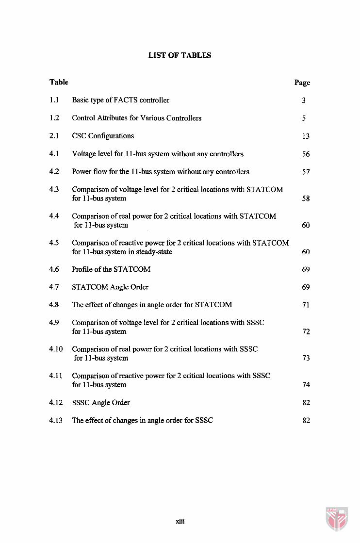
LIST OF TABLES
Table
1.1
1.2
2.1
4.1
Basic type of FACTS controller
Control Attributes for Various Controllers
CSC Configurations
Voltage level for 1 1-bus system without any controllers
Power flow for the 1 1 -bus system without any controllers
Comparison of voltage level for 2 critical locations with STATCOM for 1 1 -bus system
Comparison of real power for 2 critical locations with STATCOM for 1 1 -bus system
Comparison of reactive power for 2 critical locations with STATCOM for 1 1 -bus system in steady-state
Page
3
5
13
5 6
Profile of the STATCOM
STATCOM Angle Order
The effect of changes in angle order for STATCOM
Comparison of voltage level for 2 critical locations with SSSC for 1 1 -bus system
4.10 Comparison of real power for 2 critical locations with SSSC for 1 1 -bus system
4.1 1 Comparison of reactive power for 2 critical locations with SSSC for 1 1 -bus system
4.12 SSSC Angle Order
4.13 The effect of changes in angle order for SSSC
xiii
LIST OF FIGURES
Figure Page
2.1 CSC conceptual one-line diagram
2.2 The control of CSC
2.3 Valve for a voltage-sourced converter
2.4 Voltage-sourced converter concept
2.5 STATCOM based on voltage-sourced converter
2.6 A static synchronous compensator operated in inductive and capacitive mode
2.7 STATCOM phasor diagram(a) at ac terminal, (b) at dc terminal
2.8 SSSC based on voltage-sourced converters
2.9 SSSC is applied in transmission system
2.10 SSSC phasor diagram(a) at ac terminal, (b) at dc terminal
3.1 One line diagram for 1 1 - bus system
3.2 The 1 1-bus system model in PSCADEMTDC
3.3 Research methodology flow chart
3.4 The 1 1-bus system with STATCOM in parallel with either bus 7 or bus 8.
3.5 The 1 1-bus system model in PSCADEMTDC with STATCOM connected to either bus 7 or bus 8
3.6 The 1 1-bus system with SSSC in series with either line 7-8b or line 8-9b
3.7 The 1 1-bus system model in PSCADIEMTDC with SSSC in series with either line 7-8b or line 8-9b
3.8 Basic STATCOM control scheme
3.9 Basic SSSC control scheme
3.10 AC voltage or reactive power direct control for STATCOM
xiv
3.1 1 AC voltage direct control is compared to a sawtooth PLL signal for SSSC
3.12 Generation of triangular waveforms for STATCOM
3.1 3 Generation of reference sine waveforms for STATCOM
3.14 Generation of reference sine waveform for SSSC
3.1 5 Interpolated Firing Pulse Component for STATCOM
3.1 6 Interpolated Firing Pulse Component for SSSC
Per-unit voltage magnitude at (i) bus 5, (ii) bus 6, (iii) bus 7 and (iv) bus 8, when STATCOM is applied in 1 1 -bus system
Per-unit voltage magnitude at (v) bus 9, (vi) bus 10 and (vii) bus 1 1, when STATCOM is applied in 1 1-bus system.
Real power flow for (i) line 5-6, (ii) line 6-7 and (iii) line 7-8 when STATCOM is applied in 1 1 -bus system.
Real power flow for (iv) line 8-9, (v) line 9- 10 and (vi) line 10-1 1, when STATCOM is applied in 1 1 -bus system.
Reactive power flow for (i) line 5-6, (ii) line 6-7 and (iii) line 7-8, when STATCOM is applied in 1 1 -bus system.
Reactive power flow for (iv) line 8-9, (v) line 9- 1 0 and (vi) line 10- 1 1, when STATCOM is applied in 1 1-bus system. 68
STATCOM performance when added to 1 1 -bus system.
Active and reactive power in receiving end
Per-unit voltage magnitude at (i) bus 5, (ii) bus 6, (iii) bus 7 and (iv) bus 8, when SSSC is applied in 1 1-bus system
4.10 Per-unit voltage magnitude at (v) bus 9, (vi) bus 10 and (vii) bus 1 1, when SSSC is applied in 1 1 -bus system
4.1 1 Real power flow for (i) line 5-6, (ii) line 6-7 and (iii) line 7-8, when SSSC is applied in 1 1-bus system
4.12 Real power flow for (iv) line 8-9, (v) line 9- 10 and (vi) line 10-1 1, when SSSC is applied in 1 1 -bus system
4.13 Reactive power flow for (i) line 5-6, (ii) line 6-7 and (iii) line 7-8, when SSSC is applied in 1 1 -bus system
4.14 Reactive power flow for (iv) line 8-9, (v) line 9-1 0 and (vi) line 10- 1 1, when SSSC is applied in 1 1 -bus system. 8 1
xvi
LIST OF ABBREVIATIONS
ac
CSC
dc
EMTP
FACTS
GTO
HVDC
IEEE
IPFC
MATLAB
PI
PLC
PLL
PSCADEMTDC
PWM
R & D
SPWM
SSSC
STATCOM
UPFC
VSC
Alternating Current
Convertible Static Compensator
Direct Current
Electromagnetic Transient Program
Flexible AC Transmission System
Gate Turn Off
High Voltage DC Transmission
The Institute of Electrical and Electronics Engineers
Interline Power Flow Controller
MATrix LABoratory
Proportional Integral
Power Line Carrier
Phase Locked Loop
Power System CAD~Electromagnetic Transient DC
Pulse Width Modulation
Research and Development
Sinusoidal PWM
Static Synchronous Series Compensator
Static Synchronous Compensator
Unified Power Flow Controller
Voltage-sourced Converter
xvii
CHAPTER 1
INTRODUCTION
This part describes the introduction to the research work. It will explain about the
objectives, scope of work, research methodology and organization of the thesis.
1.1 Flexible AC Transmission System
As the growth of complex electrical power network, a new approach called Flexible
Alternating Current Transmission System (FACTS) has been implemented to
increase the capability of the existing transmission systems. Through this approach,
new power electronic controllers with high-current, high-voltage were introduced to
control voltage level and power flows on transmission system without decreasing the
system stability and security [ 1,2].
Hingorani, as the pioneer has put forward FACTS, and aimed to transport the control
technology based on thyristor into the ac system [2-41. FACTS is adopt modem
power electronics application at the important location of the transmission system in
order to control and adjust one or more of the main parameters of the transmission
system, to enhance the value of ac transmission assets [3]. These parameters include
voltages, impedance, phase angle, current, active power and reactive power [4]. The
application of FACTS proved that the technology brings many benefits to the world
and there are many areas for improvement. In the meantime, current researches are
focused to increase its effectiveness.
FACTS involves reliable and high-speed power electronic switches instead of
mechanically controlled devices. FACTS is also supported by advances in digital
protective relays, digital controls, integrated communications and advanced control
centers [2,5,6]. The heart of FACTS is thyristors: small, high voltage, semiconductor
based devices that can switch electricity at megawatt levels within milliseconds [4,7].
Each controller in FACTS employs thyristor in various configurations to perform
different functions.
In general, FACTS controllers can be divided into four categories. The controllers
are series controllers, shunt controllers, combined series-series controllers and
combined series-shunt controllers 141. The description for each controller is shown in
Table 1.1 [4].
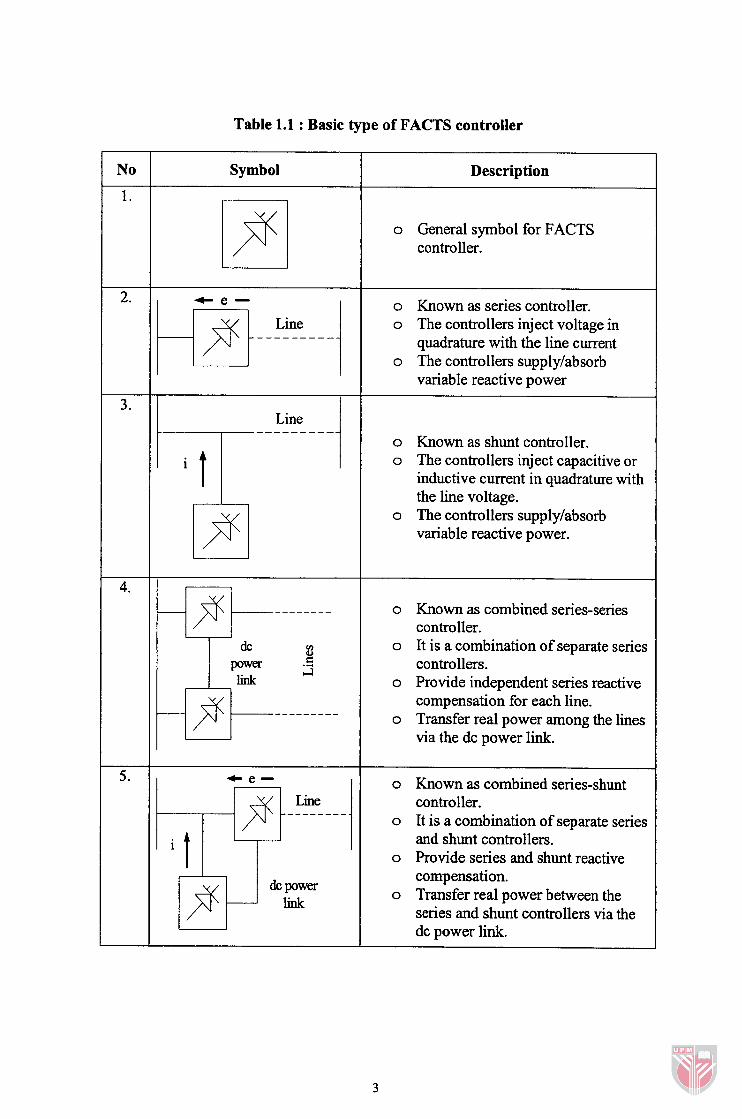
Table 1.1 : Basic type of FACTS controller
Symbol Description
o General symbol for FACTS controller.
--
o Known as series controller. o The controllers inject voltage in
quadrature with the line current o The controllers supplylabsorb
variable reactive power
o Known as shunt controller. o The controllers inject capacitive or
inductive current in quadrature with the line voltage.
o The controllers supply/absorb variable reactive power.
o Known as combined series-series controller.
o It is a combination of separate series controllers.
o Provide independent series reactive compensation for each line.
o Transfer real power among the lines via the dc power link.
o Known as combined series-shunt controller.
o It is a combination of separate series and shunt controllers.
o Provide series and shunt reactive compensation.
o Transfer real power between the series and shunt controllers via the dc power link.
FACTS controllers have been successfblly implemented around the world. The
following situations demonstrate the advantages of FACTS controller when it is put
into practice [3,4,8]. Basically, different types of controllers will illustrate different
attributes.
1. Control power flow so that it flows on the prescribed transmission routes.
2. Increase the loading capacity of transmission lines to their thermal
capabilities.
3. Increase the system security through raising the transient stability limit,
limiting short-circuit currents and overloads, managing cascading outages
and damping of power systems oscillations.
4. Provide secure tie line connections to neighboring utilities and regions
thereby decreasing overall generation reserve requirements on both sides.
Provide greater flexibility in siting new generation.
Upgrade of lines. FACTS redirects electric flow to improve utilization of
existing transmission network.
Reduce reactive power flows, thus allowing the lines to transmit more
active power.
Reduce loop flows.
Increase utilization of lowest cost generation. When this cannot be done,
it follows that there is not enough cost-effective transmission capacity.
Cost-effective enhancement of capacity will therefore allow increased use
of lowest cost generation.
FACTS improves system stability that enables higher power transfer
levels over greater distances.
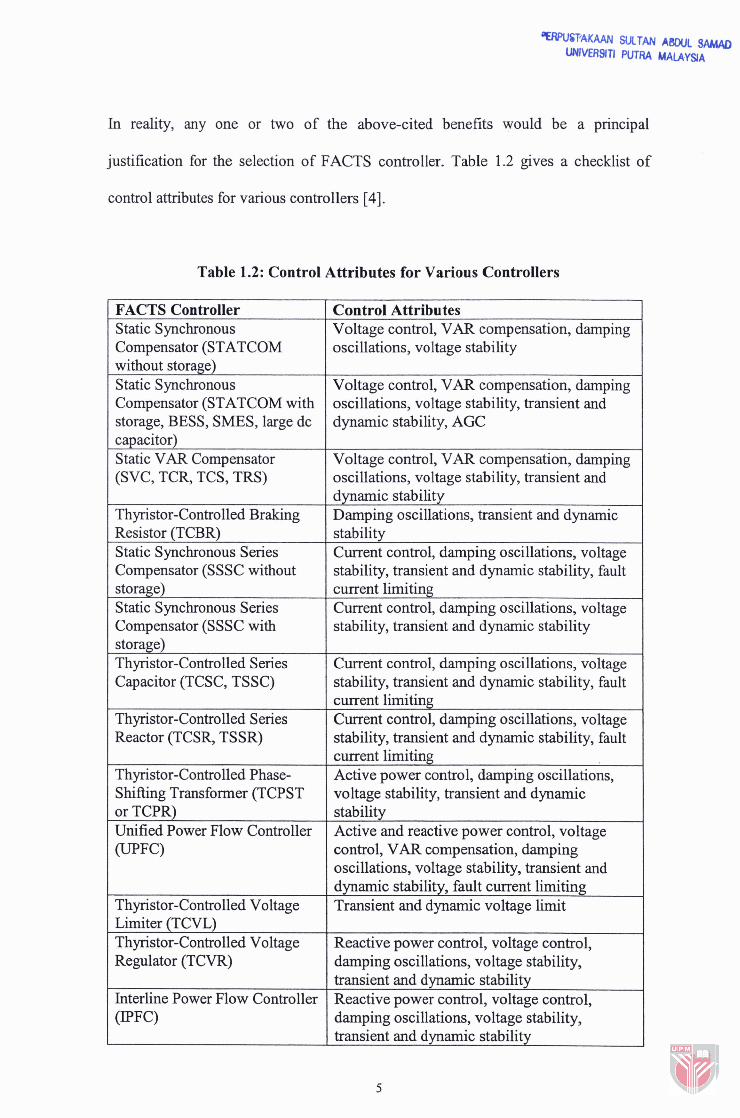
In reality, any one or two of the above-cited benefits would be a principal
justification for the selection of FACTS controller. Table 1.2 gives a checklist of
control attributes for various controllers [4].
Table 1.2: Control Attributes for Various Controllers
FACTS Controller Static Synchronous Compensator (STATCOM without storage) Static Synchronous Compensator (STATCOM with storage, BESS, SMES, large dc ca~acitor) Static VAR Compensator (SVC, TCR, TCS, TRS)
Thyristor-Controlled Braking Resistor (TCBR) Static Synchronous Series Compensator (SSSC without storage) Static Synchronous Series Compensator (SSSC with storage) Thyristor-Controlled Series Capacitor (TCSC, TSSC)
Thyristor-Controlled Series Reactor (TCSR, TSSR)
Thyristor-Controlled Phase- Shifting Transformer (TCPST or TCPR) Unified Power Flow Controller
Thyristor-Controlled Voltage - ~imiter (TCVL) Thyristor-Controlled Voltage Regulator (TCVR)
Interline Power Flow Controller (IPFC)
Voltage control, VAR compensation, damping oscillations, voltage stability, transient and dynamic stability, AGC
Voltage control, VAR compensation, damping oscillations, voltage stability, transient and dvnamic stabilitv Damping oscillations, transient and dynamic I stability Current control, damping oscillations, voltage stability, transient and dynamic stability, fault ~ current limiting Current control, damping oscillations, voltage stability, transient and dynamic stability - 1
Current control, damping oscillations, voltage stability, transient and dynamic stability, fault current limiting Current control, damping oscillations, voltage stability, transient and dynamic stability, fault current limiting Active power control, damping oscillations, voltage stability, transient and dynamic stability Active and reactive power control, voltage control, VAR compensation, damping oscillations, voltage stability, transient and dvnamic stabilitv. fault current limiting Transient and dynamic voltage limit
Reactive power control, voltage control, damping oscillations, voltage stability, transient and dynamic stability Reactive power control, voltage control, damping oscillations, voltage stability, transient and dynamic stability
1.2 Research Background
Due to deregulation of electricity markets, the need for new power flow controllers
will certainly increase. The FACTS controllers offer the corrections of transmission
capability, in order to fully utilize existing transmission system and controlling
power flow while maintaining the system reliability [9]. FACTS controllers are
based on high-power electronic switching devices called thyristors. The thyristor has
indeed revolutionized the high power industry due to higher reliability, low cost,
ruggedness and lower maintenance.
FACTS application studies require careful planning and coordination in the
specification, design and operating stage of project. Before meaningful results can be
expected from the application studies, representative models for the transmission
system and relevant FACTS controllers need to be established and verified.
In this research work, it will focus on STATCOM and SSSC for Convertible Static
Compensator (CSC) as shunt and series controller, respectively. The CSC is
employing a combination of FACTS and conventional technologies. Depending on
control needs and objectives of CSC, manipulation of the disconnect switches, circuit
switches and circuit breakers provides four primary control modes. The CSC can
h c t i o n as a STATCOM, SSSC, UPFC and PFC to improve the capability as well
as flexibility of power system [lo, 1 11.
This research addresses the problem of regulating voltage and controlling power flow
in power system using STATCOM and SSSC. These controllers are also known as
controlled reactive-power compensation devices. It provides the desired reactive
power generation or absorption especially at the point of connection. Evaluation on
the performance of these two controllers in steady state operation will be presented.
Since the most important device for FACTS controllers are made of thyristor, Gate
Turn-Off Thyristor (GTO) is used as the basic element of the voltage-sourced
converter STATCOM and SSSC in this research. The GTO device is chosen because
it facilitates current turn-on as well as turn-off by using control signals. Furthermore,
high-power GTOs are now available (100 mrn, 6 kV or 150 mm, 9 kV) due to rapidly
grown technology in this area [12].
In order to study in detail about the STATCOM and SSSC, the 1 1 -bus system has
been chosen to be implemented as a test system in PSCADIEMTDC. This system is
introduced in reference [13] and some researchers also used the 11-bus system as
their test system, as in reference [14] and [15]. The 1 1 -bus system is a simple two-
area system, which is suitable to illustrate the STATCOM and SSSC model. This
system is divided into two areas, area 1 and area 2. Area 1 has to supply power to
area 2 to overcome huge load at bus 9 [13,14]. The test system consists of several
transmission lines of various lengths, which are 10 km, 25 km and 1 10 km.