UNIVERSITI TEKNIKAL MALAYSIA MELAKA - eprints.utem.edu.myeprints.utem.edu.my/19722/1/Development Of...
24
UNIVERSITI TEKNIKAL MALAYSIA MELAKA DEVELOPMENT OF CONTROL FAN SPEED BY AUTOMATIC TEMPERATURE SENSOR USING ARDUINO This report submitted in accordance with requirement of the Universiti Teknikal Malaysia Melaka (UTeM) for the Bachelor’s Degree in Electronic Engineering Technology (Electronic Industry) (Hons.) by MOHAMAD ALIFF BIN OSMAN B071310073 900308-01-6089 FACULTY OF ENGINEERING TECHNOLOGY 2016
Transcript of UNIVERSITI TEKNIKAL MALAYSIA MELAKA - eprints.utem.edu.myeprints.utem.edu.my/19722/1/Development Of...
UNIVERSITI TEKNIKAL MALAYSIA MELAKA
DEVELOPMENT OF CONTROL FAN SPEED BY AUTOMATIC
TEMPERATURE SENSOR USING ARDUINO
This report submitted in accordance with requirement of the Universiti Teknikal
Malaysia Melaka (UTeM) for the Bachelor’s Degree in Electronic Engineering
Technology (Electronic Industry) (Hons.)
by
MOHAMAD ALIFF BIN OSMAN
B071310073
900308-01-6089
FACULTY OF ENGINEERING TECHNOLOGY
2016
UNIVERSITI TEKNIKAL MALAYSIA MELAKA
BORANG PENGESAHAN STATUS LAPORAN PROJEK SARJANA MUDA
TAJUK: Development of Control Fan Speed by Automatic Temperature Sensor Using Arduino
SESI PENGAJIAN: 2016/17 Semester 1 Saya MOHAMAD ALIFF BIN OSMAN mengaku membenarkan Laporan PSM ini disimpan di Perpustakaan Universiti Teknikal Malaysia Melaka (UTeM) dengan syarat-syarat kegunaan seperti berikut:
1. Laporan PSM adalah hak milik Universiti Teknikal Malaysia Melaka dan penulis. 2. Perpustakaan Universiti Teknikal Malaysia Melaka dibenarkan membuat salinan
untuk tujuan pengajian sahaja dengan izin penulis. 3. Perpustakaan dibenarkan membuat salinan laporan PSM ini sebagai bahan
pertukaran antara institusi pengajian tinggi.
4. **Sila tandakan ( )
SULIT
TERHAD
TIDAK TERHAD
(Mengandungi maklumat yang berdarjah keselamatan atau kepentingan Malaysia sebagaimana yang termaktub dalam AKTA RAHSIA RASMI 1972)
(Mengandungi maklumat TERHAD yang telah ditentukan oleh organisasi/badan di mana penyelidikan dijalankan)
Alamat Tetap:
No. 65 Jalan AP 7,
Taman Alai Perdana,
Crystal Bay, 75460 Melaka.
Tarikh: ________________________
Disahkan oleh:
Cop Rasmi: Tarikh: _______________________
** Jika Laporan PSM ini SULIT atau TERHAD, sila lampirkan surat daripada pihak berkuasa/organisasi berkenaan dengan menyatakan sekali sebab dan tempoh laporan PSM ini perlu dikelaskan sebagai SULIT atau TERHAD.
DECLARATION
I hereby, declared this report entitled Development of Control Fan Speed By
Automatic Temperature Sensor Using Arduino is the results of my own research
except as cited in references.
Signature : ……………………………………..
Author’s Name : MOHAMAD ALIFF BIN OSMAN
Date : 18 December 2016

APPROVAL
This report is submitted to the Faculty of Engineering Technology of UTeM as a
partial fulfilment of the requirements for the degree of Bachelor of Engineering
Technology (Industrial Electronics) with Honours. The member of the supervisory is
as follow:
………………………………………..
(Encik Ahmad Sayuthi Bin Mohd Shokri)
i
ABSTRAK
Projek ini bertujuan untuk mengkaji dan memperbaharui aplikasi kawalan kelajuan
kipas lama yang menggunakan kawalan secara manual, kepada cara kawalan
kelajuan kipas yang baru secara automatik dengan menggunakan teknik bacaan suhu
semasa bilik oleh penderia suhu. Sistem kawalan kelajuan kipas lama yang
menggunakan cara manual adalah teknik yang masih di guna pakai semenjak dari
dahulu kala kipas dicipta sehingga kini. Kelajuan kipas lama ditentukan oleh
kawalan tangan pengguna yang menentukannya, ianya menyukarkan dan
memerlukan tenaga pengguna untuk mengawal kelajuannya. Manakala, dengan
adanya kawalan kipas secara automatik ini, ianya memudahkan, menjimatkan kos bil
elektrik dan kos tenaga pengguna. Malahan ianya tampak lebih sistematik dan
berteknologi, dengan paparan suhu semasa bilik dan kelajuan kipas yang sedang
berputar. Justeru itu, kawalan kipas automatik ini tidak menggunakan kawalan suis
buka atau tutup secara manual, ianya menggunakan alat penderia bunyi untuk
mengesan bunyi tepukan tangan bagi menghidupkan atau mematikan suis. Malahan
ianya ditambah pula dengan kawalan suis had yang dipasangkan di pintu utama bilik
ataupun rumah, yang berfungsi untuk mematikan suis dan fungsi kipas jika pengguna
terlupa untuk mematikan suis dengan tepukan tangan ketika ingin keluar dari rumah.
Keseluruhan proses ini dilakukan dengan pemprograman yang telah ditetapkan
dalam Arduino UNO, yang melaksanakan gerak kerja dari proses awal hingga akhir.
ii
ABSTRACT
The project aims to study and renew old fan speed control applications using manual
control, to control how the new fan speed automatically using the current
temperature reading room by the temperature sensor. Old fan speed control system
using the manual method is a technique that still prevails since ancient fan created
until now. Old fan speed is determined by the user's hand control to define it; it's
difficult and requires energy users to control its speed. Whereas, with this automatic
fan control, it's convenient, cost-effective electricity bills and energy costs
consumers. In fact, it looks more systematic and technologically, to display the
current room temperature and fan speed spinning. Therefore, the automatic fan
control does not use a control switch on or off manually, it uses sound sensors to
detect the sound of applause to turn on or turn off the switch. In fact it is coupled
with the control limit switch installed at the main entrance of the room or house,
which serves to turn off the switch and fan function if users forget to turn off the
switch with applause when they want out of the house. This whole process is done
with the programming that has been set in the Arduino UNO, who carries out the
work from the beginning to the end.
iii
DEDICATION
To my beloved parents, family members and friends.
iv
ACKNOWLEDGEMENT
In the name of Allah s.w.t. , the Most Beneficent and the Most Merciful. A
deep sense of thankfulness to Allah s.w.t. who was has given me the full strength,
ability, and patience to complete this Bachelor Degree Project as it is today.
Firstly, I would like to take this opportunity to put into words my deepest
gratitude and appreciation to my project supervisor Madam Nurliyana Binti Mutalib
and my co-supervisor Mr Ahmad Sayuthi Bin Mohd Shokri for the support,
guidance, patience, encouragement, and abundance of ideas during the completion of
this project. Secondly, special thanks to both honourable panels, for their comments,
invaluable suggestions, and outstanding deliberations
to improve the project during the project presentation.
I would also like to express my extraordinary appreciation to my family
especially to my parents, Mr Osman Bin Samat and Madam Ami Bte Atan and also
to my family members for their invaluable support along the duration of my studies
until the completion of this Bachelor Degree Project. Finally, yet importantly, thanks
to my beloved friends who are directly or indirectly contributed due to their supports
and guidance and helped greatly to point me in the right direction until the
completion of this Bachelor Degree Project.
v
TABLE OF CONTENT
Abstrak i
Abstract ii
Dedication iii
Acknowledgement iv
Table of Content v
List of Tables ix
List of Figure x
List of Abbreviations, Symbols and Nomenclature xiii
CHAPTER 1: INTRODUCTION
1.1 Introduction 1
1.2 Background 1
1.3 Problem Statement 2
1.4 Objectives 2
1.5 Scope of project 2
1.6 Outline of Project Report 3
CHAPTER 2: LITERATURE REVIEW
2.1 Introduction 4
2.2 Research from previous project 4
2.3 Hardware and Software review 6
vi
2.3.1 Temperature Sensor (LM35) 6
2.3.2 Light-Emitting Diode (LED) 7
2.3.3 LCD Displays 8
2.3.4 Transistor (NPN) 9
2.3.5 Condenser Microphone 11
2.3.6 Arduino Microcontroller 12
2.3.6.1 Arduino UNO 12
2.3.6.2 Advantages of Arduino UNO 13
CHAPTER 3: METHODOLOGY
3.1 Introduction 15
3.2 Project Planning 15
3.3 Project Flowchart 17
3.4 Block Diagram 18
3.5 Hardware Implementation 20
3.5.1 Circuit Interfacing of Arduino Uno with Sound Sensor 20
3.5.2 Circuit Interfacing of Arduino UNO with Temperature Sensor 21
3.5.3 Circuit Interfacing of Arduino UNO with LCD Display 22
3.6 Software Implementation 23
3.6.1 Arduino UNO Program Structure 23
3.6.2 Flowchart of Arduino UNO Program for this Project System 24
vii
CHAPTER 4: RESULT AND DISCUSSION
4.1 Introduction 26
4.2 Project Prototype 26
4.3 Schematic Diagram from Proteus 8.0 Convert to Printer 27
4.4 Schematic Diagram of Power Supply Circuit 28
4.5 Hardware Development and Experimental Works 29
4.6 Software Development and Experimental Works 30
4.6.1 General Process of Arduino UNO Programming 30
4.7 Experimental Results 33
4.7.1 Analysis of PWM value from oscilloscope measurement 33
4.7.2 Graph of Relationship between Temperature and PWM 44
Value from 0 until 255
4.7.3 Graph of Relationship between Temperature and PWM 45
Voltage from 0 Volt until 5 Volt
CHAPTER 5: CONCLUSION AND RECOMMENDATION
5.1 Introduction 48
5.2 Research Objectives 48
5.3 Significance of Research 48
5.4 Recommendation 49
5.5 Project Potential Commercial 49
viii
REFERENCES 50
APPENDICES
A Coding of Program

ix
LIST OF TABLES
2.1 Characteristics of Temperature Sensor LM35 7
2.2
4.1
4.2
Characteristics of Sound Sensor
Calculation of PWM value and PWM (%)
Data Calculation for PWM Voltage
11
33
45
x
LIST OF FIGURES
1.1 The block diagram of operation 3
2.1 Ultrasonic Ranging Module 6
2.2 Light-Emitting Diode 7
2.3 LCD Displays 8
2.4
2.5
2.6
Transistor (NPN)
Condenser Microphone
The Architecture of Arduino UNO
9
11
13
3.1 Flow Chart of Project Planning 17
3.2
3.3
Block Diagram for Project Development
Block Diagram of Hardware Implementation
18
19
3.4 Circuit Interfacing of Arduino UNO with Sound Sensor 20
3.5
3.6
3.7
3.8
Circuit Interfacing of Arduino UNO with Temperature Sensor
Circuit Interfacing of Arduino UNO with LCD Display
Example full program in the Arduino UNO
Flowchart of Overall Process in Arduino UNO
21
22
23
25
xi
4.1
4.2
4.3
4.4
4.5
4.6
4.7
4.8
4.9
4.10
4.11
4.12
4.13
4.14
4.15
4.16
4.17
4.18
4.19
4.20
4.21
Connection of the Schematic diagram from Proteus 8.0
Converts to Printer
Schematic diagram Connection of Power Supply
Hardware Implementation and Experimental Works Connection
Input Output Pin Assignment for LCD Display
Temperature Sensor Initialize Setup
Speed of Fan Initializes Setup
Input Output of Hand Claps Sensor and Initialize Setup
Input Output of Limit Switch and Initialize Setup
LCD Display at Current Temperature 26˚C and Fan Speed at 10%
The Output Result of Oscilloscope at Duty Cycle 10%
LCD Display at Current Temperature 27˚C and Fan Speed at 20%
The Output Result of Oscilloscope at Duty Cycle 20%
LCD Display at Current Temperature 28˚C and Fan Speed at 30%
The Output Result of Oscilloscope at Duty Cycle 30%
LCD Display at Current Temperature 29˚C and Fan Speed at 40%
The Output Result of Oscilloscope at Duty Cycle 40%
LCD Display at Current Temperature 30˚C and Fan Speed at 50%
The Output Result of Oscilloscope at Duty Cycle 50%
LCD Display at Current Temperature 31˚C and Fan Speed at 60%
The Output Result of Oscilloscope at Duty Cycle 60%
LCD Display at Current Temperature 32˚C and Fan Speed at 70%
27
28
29
30
31
31
31
32
34
34
35
35
36
36
37
37
38
38
39
39
40
xii
4.22
4.23
4.24
4.25
4.26
4.27
4.28
4.29
4.30
The Output Result of Oscilloscope at Duty Cycle 70%
LCD Display at Current Temperature 33˚C and Fan Speed at 80%
The Output Result of Oscilloscope at Duty Cycle 80%
LCD Display at Current Temperature 34˚C and Fan Speed at 90%
The Output Result of Oscilloscope at Duty Cycle 90%
LCD Display at Current Temperature 35˚C and Fan Speed at 100%
The Output Result of Oscilloscope at Duty Cycle 100%
Relationship between Temperature and PWM value
Graph of Relationship between Temperature and PWM voltage
40
41
41
42
42
43
43
44
46
xiii
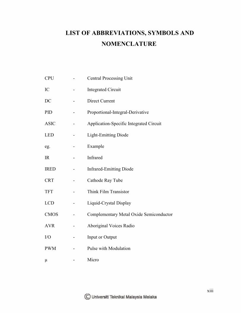
LIST OF ABBREVIATIONS, SYMBOLS AND
NOMENCLATURE
CPU - Central Processing Unit
IC - Integrated Circuit
DC - Direct Current
PID - Proportional-Integral-Derivative
ASIC - Application-Specific Integrated Circuit
LED - Light-Emitting Diode
eg. - Example
IR - Infrared
IRED - Infrared-Emitting Diode
CRT - Cathode Ray Tube
TFT - Think Film Transistor
LCD - Liquid-Crystal Display
CMOS - Complementary Metal Oxide Semiconductor
AVR - Aboriginal Voices Radio
I/O - Input or Output
PWM - Pulse with Modulation
µ - Micro
1
CHAPTER 1
INTRODUCTION
1.1 Introduction
This chapter includes overall about the project background, problem
statement, objectives, scope, and outline of the project in order to give an overall
view of the project.
1.2 Background
As we know, today fan is control the speed by manual. This project is to
design a fan speed which is controlling by automatic temperature sensor using an
Arduino UNO microcontroller. The system is designed to convert existing fan
controlled by manual ways to automatic temperature reading. The temperature sensor
is used for taking temperature in a room. Room temperature reading is taken to
determine the rotation speed of the fan to meet the convenience of users. The room
temperature had been measured and speed of fan will be display at LCD. Arduino
UNO microcontroller used in this project, as the application when we hand claps and
the switch will turn ON automatically to moves the operating function to read the
room temperature and determine speed of fan. To turn off the switch, the user must
claps hand again to turn OFF the fan and switch. Furthermore, the limit switch is
used at the room door or main door to turn OFF the switch and function of fan. This
fan function is designed as an enhancement to the existing fan system nowadays.
2
1.3 Problem Statement
This project is about to create new function for activate the switch ON/OFF at
supply automatically using hand claps and to control the speed of fan by automatic
temperature sensor using Arduino UNO. This old function need to be changed
because the fan today is functioning manually to control the speed of fan for given
comfort to the users. There are lots of steps for control the speed of fan, if the old
function still used it’s not parallel to development of technology nowadays.
1.4 Objectives
The main objectives of the project as below:-
1) To learn how to use the Arduino UNO Microcontroller.
2) To learn how to do a program for detect hand claps, temperature and control speed of fan.
3) To design a circuit automatic temperature and implement the process
1.5 Scope of Project
This function is build based on the previous model of fan and for build this
function the hardware and software is used. The important part use in this project is a
Arduino UNO Microcontroller. The Arduino UNO microcontroller functioning as a
main part for controls this function. Among them is to control switch ON/OFF, limit
switch, set the speed of fan for low, medium and high based on room temperature
that are taken automatically by using temperature sensor. The programming uses in
this project will be compile using Arduino UNO software and then been upload into
the Arduino UNO microcontroller to implement the process. All the process that’s
have been set up in the program to generate speed of fan using automatic temperature
measurement. To simulate the circuit Proteus 8.0 software is used in order to know
the circuits function.
3
1.6 Outline of Project Report
The outline project of this report is separate into five sections to make clearly
view about this project. The first section of this project is to elaborate strongly about
the system operation and hardware that has been made in this project to make sure
it’s along and parallel with the aims and objectives of this final year project. Some
review paper from the past and previous of researches with the same topic was been
explain into section two. For the section three, it more to explain the details about the
method or the way and to make the implementation steps of this project. Section four
is discussed all the findings, results, discussion, and analysis about this project. And
lastly of the section of this project is section five that to summarize the conclusion
and made recommendation for future study that can use to improve for this project.
4
CHAPTER 2
LITERATURE REVIEW
2.1 Introduction
In this chapter, the literature review which contains the information and ideas
in completing the project is discussed. There are several sources that had been taken
as a resource such as books, thesis, journal and website. It was included the operation
of the circuit, the hardware and software which is useful in the project. Other than
that, in this chapter also make a study about several projects that related to make
some improvement or take some idea from the other project. It is useful to complete
a project that has been created and we compared this project from the previous
project to make this project more efficient and systematic.
2.2 Research from Previous Project
Based on the previous project, it was needed as the references to complete
this project successfully. It was useful to upgrade and modified the system that has
been demonstrate before. Other than that, according to current developments, the
latest technology used in this project to solve the problems faced at present.
One of system is a smart fan for human tracking using PIC16F73 (Tajrin
Ishrat 2014). A research work focused on automatic person detection system by
using IR sensor detection accuracy decreases with increasing reflection distance and
change in detection results due to the differences in weather conditions. The system
was implemented by using ultrasonic distance sensor to minimize the sensor’s
limitation for human tracking system compare [1], then this project is using the
5
temperature sensor LM35 for reading temperature in room. Other than that, this
concept using a lot of money because used the ultrasonic distance sensor and the
costing of maintenance is more expensive.
The next project is global fan speed control considering non-ideal
temperature measurements in enterprise servers (Jungsoo Kim 2014). The system
was implemented by using Proportional-Integral-Derivative (PID) controller to the
operating fan speed and eliminating fan speed oscillation caused by temperature
quantization [2], and then this project is use the Arduino UNO to save the cost and
easy to develop. The different from previous research that are design to control speed
of fan at CPU temperature and this project is to design the control speed of fan in
room temperature.
From the previous project a monolithic fan speed control IC for monitoring
temperature and improving power efficiency (Yuan-Ta Hsieh 2012), this project is
using thermal sensors to monitor the temperature within the ASIC and a boost DC-
DC converter to drive cooling fans and improve power efficiency [3]. The thermal
sensor is used for detect human temperature at surrounding difference with this
project is using the LM35 sensor for reading the temperature in room.
Another more, from the previous project is about automatic fan speed control
system using microcontroller that has a similarity with this project (Mustafa Saad
2014). The project is use a LM35 temperature sensor to measure the temperature and
display on the LCD the temperature and speed of fan. But in this project, they are
used PIC16F877A microcontrollers to apply in this function and differences with this
project that used an Arduino UNO to control a speed of fan, sound sensor circuit;
temperature sensor circuit, LCD display and limit switch circuit. This previous
project is just controls the speed of fan by current temperature and shows the speed
of fan in rpm at LCD display [4], different with this project that use average
percentage that been set in instruction, that is 0%, 10%, 20% until 100%.
Furthermore, from the previous project automatic temperature controlled fan
using thermistor (Sushma Verma JULY 2016). The project is use a thermistor as
sensor for read the current temperature. The concept is read the temperature from PC
to control the speed of fan respectively increases and decreases by automatically [5].
That not used any microcontroller to control the process.
6
Moreover, from the previous project room temperature based fan speed
control system using pulse width modulation technique (Vaibhav Bhatia
NOVEMBER 2013). This previous project is use the temperature LM35 to detect the
temperature at room. The process to design also used the Proteus 8.0. The different
with this project is the microcontroller used the in the project, they are used the
MATLAB R2013a v1.8 to authorize the accuracy of the structure and at this project
used the Arduino UNO [6].
2.3 Hardware and Software Review
In this part is to review the hardware and software equipment that are used in
this project. Some explanation about functioning and information regarding parts and
components for the hardware to observed the different between the specifications to
develop this project.
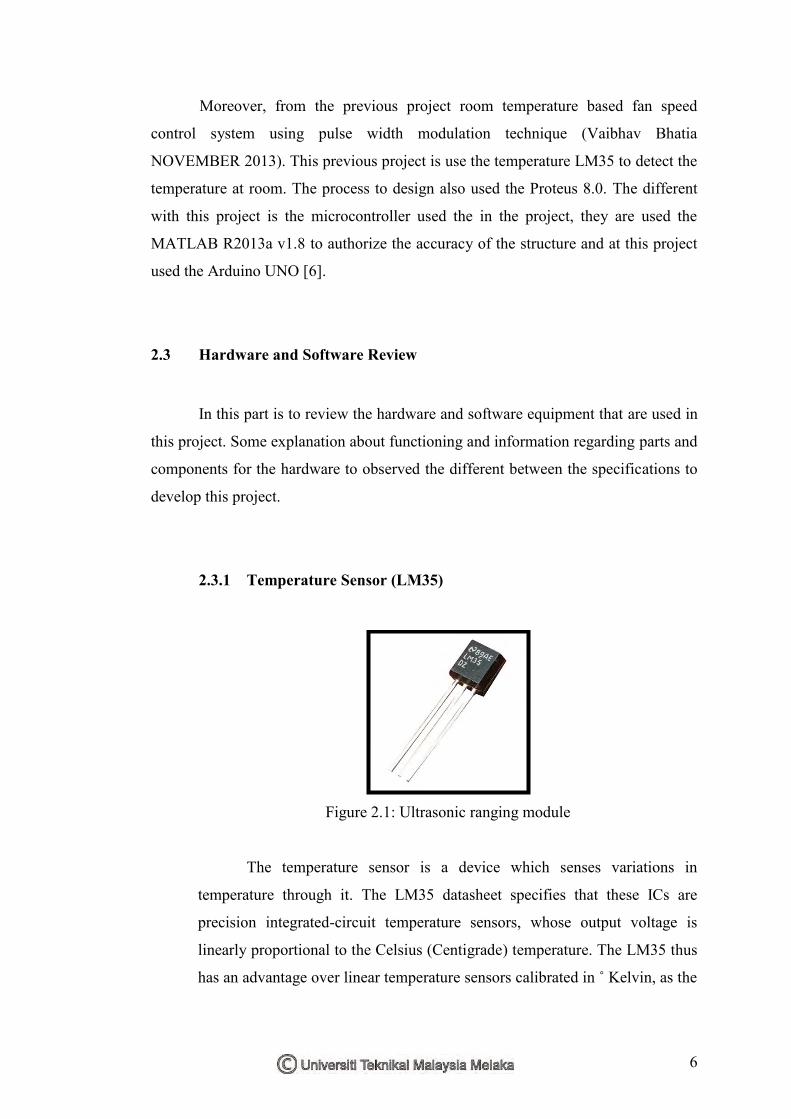
2.3.1 Temperature Sensor (LM35)
Figure 2.1: Ultrasonic ranging module
The temperature sensor is a device which senses variations in
temperature through it. The LM35 datasheet specifies that these ICs are
precision integrated-circuit temperature sensors, whose output voltage is
linearly proportional to the Celsius (Centigrade) temperature. The LM35 thus
has an advantage over linear temperature sensors calibrated in ˚ Kelvin, as the
7
user is not required to subtract a large constant voltage from its output to
obtain convenient Centigrade scaling. The LM35 does not require any
external calibration or trimming to provide typical accuracies of ±1⁄4˚C at
room temperature and ±3⁄4˚C over a full temperature range. This sensor is
used in this project for detect and read the temperature in room.
Table 2.1: Characteristics of temperature sensor LM35
Parameter Description
Supply Voltage 4 to 30 Volt
Temp. Range -55 to +150 ˚C
Accuracy ±2 ˚C
Output +10mVolt/ ˚C
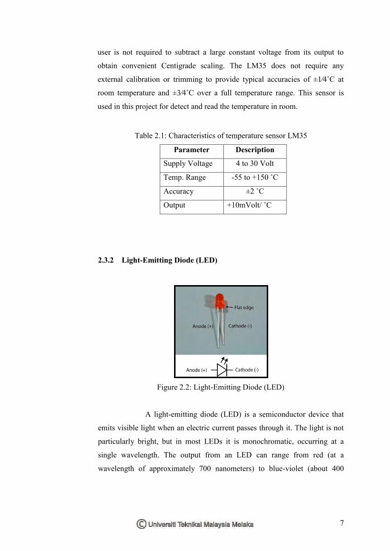
2.3.2 Light-Emitting Diode (LED)
Figure 2.2: Light-Emitting Diode (LED)
A light-emitting diode (LED) is a semiconductor device that
emits visible light when an electric current passes through it. The light is not
particularly bright, but in most LEDs it is monochromatic, occurring at a
single wavelength. The output from an LED can range from red (at a
wavelength of approximately 700 nanometers) to blue-violet (about 400