UTeM Library (Pind.1/2007)eprints.utem.edu.my/6337/1/Critical_QA_And_QC_Process_Procedure_In... ·...
24
Transcript of UTeM Library (Pind.1/2007)eprints.utem.edu.my/6337/1/Critical_QA_And_QC_Process_Procedure_In... ·...
UTeM Library (Pind.1/2007)
UNIVERSITI TEKNIKAL MALAYSIA MELAKA
BORANG PENGESAHAN STATUS TESIS*
JUDUL: CRITICAL QA AND QC PROCESS PROCEDURE IN PRESSURE VESSEL FABRICATION
SESI PENGAJIAN: SEMESTER 2 TAHUN 4 (2008)
Saya _______RADEN AHMAD MUHAIMIN BIN HUMAIDI____________________
mengaku membenarkan tesis (PSM/Sarjana/Doktor Falsafah) ini disimpan di Perpustakaan Universiti Teknikal Malaysia Melaka (UTeM) dengan syarat-syarat kegunaan seperti berikut:
1. Tesis adalah hak milik Universiti Teknikal Malaysia Melaka . 2. Perpustakaan Universiti Teknikal Malaysia Melaka dibenarkan membuat salinan
untuk tujuan pengajian sahaja. 3. Perpustakaan dibenarkan membuat salinan tesis ini sebagai bahan pertukaran
antara institusi pengajian tinggi.
4. **Sila tandakan (√)
(HURUF BESAR)
SULIT
TERHAD
TIDAK TERHAD
(Mengandungi maklumat yang berdarjah keselamatan atau kepentingan Malaysia yang termaktub di dalam
AKTA RAHSIA RASMI 1972)
(Mengandungi maklumat TERHAD yang telah ditentukan
oleh organisasi/badan di mana penyelidikan dijalankan)
(TANDATANGAN PENULIS)
Alamat Tetap:
Tarikh: _______________________
Disahkan oleh:
(TANDATANGAN PENYELIA)
Cop Rasmi:
Tarikh: _______________________
* Tesis dimaksudkan sebagai tesis bagi Ijazah Doktor Falsafah dan Sarjana secara penyelidikan, atau disertasi bagi pengajian secara kerja kursus dan penyelidikan, atau Laporan Projek Sarjana Muda (PSM). ** Jika tesis ini SULIT atau TERHAD, sila lampirkan surat daripada pihak berkuasa/organisasi berkenaan dengan menyatakan sekali sebab dan tempoh tesis ini perlu dikelaskan sebagai SULIT atau TERHAD.
DECLARATION
I hereby, declared this thesis entitled
“CRITICAL QA AND QC PROCESS PROCEDURE IN PRESSURE VESSEL
FABRICATION”
is the results of my own research except as cited in references.
Signature : ………………………………………….
Author’s Name : RADEN AHMAD MUHAIMIN BIN HUMAIDI
Date : MAY 2008
APPROVAL
This PSM submitted to the senate of UTeM and has been as partial fulfillment of the
requirements for the degree of Bachelor of Manufacturing Engineering (Manufacturing
Process). The member of the supervisory committee is:
………………………………
(Engr. Sivarao A/L Subramonian)
i
ABSTRAK
Projek ini mendedahkan berkenaan kritikalnya jaminan kualiti (QA) dan kawalan kualiti
(QC) dalam kaedah dan proses bagi memastikan penghasilan pegandung tekanan yang
berkualiti. Kawalan kualiti amat penting dalam pembuatan pengadung tekanan ini
kerana tanpa pemeriksaan yang teliti ia boleh menyebabkan kegagalan pada pengandung
tekanan yang dihasilkan. Projek ini dijalankan dengan kerjasama Akra Engineering
Sdn.Bhd sebagai salah sebuah syarikat pengeluar kelengkapan minyak dan gas di
Malaysia. Projek ini menggunakan kod AMERICAN SOCIETY MECHANICAL
ENGINEERING (ASME) sebagai rujukan iaitu ASME BOILER dan PRESSURE VESSEL
CODE VIII. Proses jaminan kualiti dan kawalan kualiti ini terbahagi kepada enam
peringkat. Proses ini bermula dengan mengulaskan dokumen, kawalan bahan, proses
mereka, pemeriksaan dan ujian. Pemeriksaan yang dijalankan bermula dengan meneliti
dokumen dan kemudiannya memperbaiki setiap kesalahan dengan segera. Setiap
prosedur perlu diperiksa dibahagian ini bagi mengelakkan kesilapan dari berlaku.
Sebagai contoh, Inspection Test Plan (ITP), Welding Procedure Specification (WPS) dan
sebagainya. Peringkat seterusnya adalah kawalan material iaitu memastikan material
yang sampai daripada pembekal hendaklah selaras dengan tempahan pembelian dan
pensijilan bahan. Material yang sampai hendaklah mematuhi spesifikasi kod yang
ditetapkan. Pembuatan adalah bahagian yang perlu diberi penekanan kerana bahagian ini
memulakan proses penghasilan pengandung takanan. Setiap proses perlu diperiksa
dengan teliti bagi mengelakkan kegagalan dan kecacatan kimpalan. Peringkat
pemeriksaan dan ujian menerangkan bahawa setiap pengandung tekanan yang telah siap
akan diuji dengan Non-Destructive Examination (NDE) dan Hydrostatic Test.
ii
ABSTRACT
This project was discussed about the critical Quality Assurance (QA) and Quality
Control (QC) in process and procedure to ensure that the manufacture of pressure vessel
that been produces were in high quality. Quality control (QC) is very important in order
to produces the pressure vessel, without the details test will lead the failure to the
pressure vessel. This project was collaboration with Akra Engineering Sdn.Bhd which is
part of oil and Gas Company in Malaysia. This project also used the AMERICAN
SOCIETY MECHANICAL ENGINEERING (ASME) code as reference which is
ASME BOILER and PRESSURE VESSEL CODE VIII. Quality assurance (QA) and
quality control (QC) process were divided into 6 parts. The first part is documentation
review, material control, fabrication process, inspection and testing. The inspections
were start with the documentary check followed by repairing the defect instantly. Each
procedure should be test to prevent the defect from occur. The procedure that should be
held was Inspection Test Plan (ITP) and Welding Procedure Specification (WPS). The
material receiving inspection was to ensure that the materials that deliver were same as
the purchase order and material certificate. All the material should obeyed the
specification code that already fixed. Fabrication part was the critical part that should be
highlight because this part was the beginning of pressure vessel construction. As were
mention above, all parts should been details check in order to prevent the defect and
failure especially to the welding. The inspection and test part explains that when the
pressure vessel is already done, it then was tested by Non-Destructive Examination
(NDE) and Hydrostatic Test.
iii
DEDICATION
Special gratitude dedication to………
My dearest parents,
Mr. Humaidi Asnawi and Mrs. Mahaya Abu
For your love, care and support.
My brothers and sisters,
Raden Adisidaharta, Raden Zuhair, Raden Humairah
For your helpfulness, encouragement and confidence in me.
My lecturers,
Mr. Sivarao A/L Subramonian, Dr. Thoguluva Raghvan Vijayaram
and Mr. Mohd Amri b. Sulaiman
Thank you very much for your continued support, guidance and kind assistance in
making sure the success of my project.
My friends in UTeM,
Especially to Affendi b. Husin @ Cholan and Nurul Nadia Baharum
For helping me whenever I am in difficulties.
iv
ACKNOWLEDGEMENTS
Praise is to ALLAH SWT, from whom I come and belong. This piece of work would not
become possible without the contributions from many people and organizations. Most
importantly, I would like to acknowledge my supervisor, Mr Sivarao A/L Subramonian
for his kind assistance, constructive criticisms and observations in this degree project. A
special thank you for my degree project examiner, Mr. Mohd Amri bin Sulaiman also to
Dr. Thoguluva Raghvan Vijayaram as my project panel. I also would like to express my
gratitude to Mr. Muhamed Zaihasren b. Muhamed Zainal, for his full contribution
regarding this project, the information, moral supports, guidance and the confidence in
me to finish this project with his company (AKRA Engineering Sdn. Bhd). Not to forget
all staffs in AKRA Engineering Sdn. Bhd for their kindly help in providing me useful
information and data where my heart will always remain. I would also like to thank my
project partner Affendi B. Husin@Cholan with his cooperation in this project. Last but
not least, special thanks to all people who involved in assisting me directly or indirectly,
in various ways to ensure my project succeeded and I am thankful to them.
91
TABLE OF CONTENTS
Abstrak…………………………………………………………………………….…………i
Abstract………………………………………………………………………….…………..ii
Dedication………………………………………………………………………….……….iii
Acknowledgement……………………………………………………………………...…...iv
Table of Contents……………………………………………………………………….…...v
List of Figures…………………………………………………………………….….…......ix
List of Tables………………………………………………………………………....…....xii
List of Appendices………………………………………………………………………...xiii
CHAPTER 1 .......................................................................................................................... 1
INTRODUCTION ................................................................................................................ 1
1.1 Project Background .................................................................................................. 1
1.2 Problem Statement ................................................................................................... 2
1.3 Objective .................................................................................................................. 2
1.4 Scope ........................................................................................................................ 3
1.5 Project summary ...................................................................................................... 3
CHAPTER 2 .......................................................................................................................... 4
LITERATURE REVIEW .................................................................................................... 4
2.1 Introduction .............................................................................................................. 4
2.2 Project Selection ...................................................................................................... 4
2.3 Pressure Vessel ........................................................................................................ 5
2.4 Project Execution Flow for Fabricator ..................................................................... 6
2.5 General Overview of Project Execution Process: .................................................... 7
2.6 Quality Assurance (QA) and Quality Control (QC) parts ....................................... 8
2.6.1 Inspection Test Plan (ITP) ................................................................................ 9
2.6.2 Welding Procedure ......................................................................................... 11
2.6.3 Welding Procedure Specification (WPS) ....................................................... 11
92
2.6.4 Procedure Qualification Record (PQR) .......................................................... 11
2.6.5 Welder Performance Qualification (WPQ) .................................................... 12
2.6.6 Other Testing Procedure ................................................................................. 12
2.7 Material Identification and Verification ................................................................ 12
2.8 Fabrication ............................................................................................................. 13
2.9 Inspection and Testing ........................................................................................... 14
2.10 Manufacturer’s Data Reports (MDR) ................................................................ 16
2.11 Literature Review from Journals .............................................................................. 17
2.11.1 Material ........................................................................................................... 17
2.11.2 Code ................................................................................................................ 18
2.11.3 Failed .............................................................................................................. 20
2.11.4 TEST ............................................................................................................... 22
2.11.5 Safety .............................................................................................................. 25
2.11.6 Inspection........................................................................................................ 28
2.11.7 Welding .......................................................................................................... 32
CHAPTER 3 ........................................................................................................................ 37
3.1 INTRODUCTION ...................................................................................................... 37
3.2 Basic Process Methodology........................................................................................ 38
CHAPTER 4 ........................................................................................................................ 40
EXPERIMENTAL SET UP AND PROCEDURE ........................................................... 40
4.1 Introduction ................................................................................................................ 40
4.2 Documentation Review .......................................................................................... 42
4.3 Material Receiving Inspection .............................................................................. 42
4.4 Marking and cutting process ................................................................................. 45
4.4.1 Marking Phase ..................................................................................................... 45
4.4.2 Quality control check Phase ................................................................................ 46
4.4.3 Cutting Phase ....................................................................................................... 49
4.4.4 Grind and edge preparation phase ....................................................................... 50
4.5 Fit-up and assembly process ....................................................................................... 50
4.5.1 Fit-up phase ......................................................................................................... 51
4.5.2 Quality control check phase ................................................................................ 52
4.6 Weld-Up Process ........................................................................................................ 54
93
4.6.1 Procedure and document reference phase ........................................................... 55
4.6.2 Equipment preparation Phase .............................................................................. 55
4.6.3 Set up welding equipment phase ......................................................................... 56
4.6.4 Welding ............................................................................................................... 57
4.6.5 Inspection Phase .................................................................................................. 60
4.7 Non destructive test (Dye Penetrant Inspection) ........................................................ 61
4.7.1 Dye penetrant inspection Procedure (Code Par UG-103, p.80): ......................... 61
4.8 Hydrostatic test ........................................................................................................... 64
4.8.1 Confirm the entire prior to hydrostatic test ......................................................... 64
4.8.2 Hydrostatic test .................................................................................................... 65
4.8.3 Inspection............................................................................................................. 66
4.8.4 Post hydro flushing & drying .............................................................................. 66
4.8.5 Weld up................................................................................................................ 67
CHAPTER 5 ........................................................................................................................ 68
5.1 Result .......................................................................................................................... 68
5.1.1 Dye penetrant inspections show the result as below: .......................................... 68
5.1.2 Hydrostatic Test Result ....................................................................................... 75
CHAPTER 6 ........................................................................................................................ 81
REFERENCES ................................................................................................................... 83
94
LIST OF FIGURES
Figure 2. 1 : AKRA Engineering Sdn. Bhd ............................................................................ 4
Figure 2. 2 : Pressure vessel ................................................................................................... 5
Figure 2. 3: Project Execution Flow Process .......................................................................... 6
Figure 2. 4: Parts of Quality Assurance (QA) and Quality Control (QC) .............................. 8
Figure 4. 1: Fabrication Flow Chart in Quality Assurance and Quality Control process .... 41
Figure 4. 2: Checked the material arrive according mill certificate .................................... 43
Figure 4. 3: Checked the material condition. ....................................................................... 43
Figure 4. 4: Material dimensional checked ......................................................................... 44
Figure 4. 5: Checked material diameter ............................................................................... 44
Figure 4. 6 : Marking and cutting process flow ................................................................... 45
Figure 4. 7: Marking for vessel size .................................................................................... 45
Figure 4. 8: Marking for vessel orientation ......................................................................... 46
Figure 4. 9: Punched the orientation to prevent from disappeared ...................................... 46
Figure 4. 11: Orientation checked at shell ........................................................................... 47
Figure 4. 12: Orientation checked at end cap ...................................................................... 48
Figure 4. 13: Checked the marking for nozzle opening ...................................................... 48
Figure 4. 14: Nozzle opening at shell .................................................................................. 49
Figure 4. 15: Nozzle opening at end cap ............................................................................. 49
Figure 4. 16: Beveling process ............................................................................................ 50
Figure 4. 17: End cap and shell fit-up using tackweld. ....................................................... 51
Figure 4. 18: Nozzle to flange fit-up ................................................................................... 51
Figure 4. 19: Fit-up check 1................................................................................................. 52
Figure 4. 20: Fit-up check 2................................................................................................. 52
Figure 4. 21: Prove that the fit-up have been checked ........................................................ 53
Figure 4. 22: Weld up process ............................................................................................. 54
95
Figure 4. 23: Baked electrode in the baking oven. .............................................................. 55
Figure 4. 24: Electrode was put in the holding oven to control electrode temperature ....... 56
Figure 4. 25: Weld for the root pass .................................................................................... 57
Figure 4. 26: Root pass ........................................................................................................ 58
Figure 4. 27: Removed all the slag from root pass .............................................................. 58
Figure 4. 28: Weld for capping pass .................................................................................... 59
Figure 4. 29: Capping pass .................................................................................................. 59
Figure 4. 30: Checked welding seam ................................................................................... 60
Figure 4. 31: Checked weld at the nozzle ............................................................................ 60
Figure 4. 32: Non-destructive test process flow .................................................................. 61
Figure 4. 33: Apply penetrant at circumferences seam ....................................................... 62
Figure 4. 34: Apply penetrant at nozzle .............................................................................. 62
Figure 4. 35: Apply developer at circumferences seam ...................................................... 63
Figure 4. 36: Apply developer at nozzle. ............................................................................. 63
Figure 4. 37: Describe indication appeared ......................................................................... 63
Figure 4. 38: Hydrostatic test process flow ......................................................................... 64
Figure 4. 39: Pumped water inside the air receiver ............................................................. 65
Figure 4. 40: Waiting for the result ..................................................................................... 66
Figure 4. 41: Drain out the water from air receiver ............................................................. 66
Figure 5. 1: Welding seam 1 does not show any surface defect ........................................... 69
Figure 5. 2: Welding seam 2 does not show any surface defect ........................................... 69
Figure 5. 3: Welding seam 3 does not show any surface defect ........................................... 70
Figure 5. 4: Welding seam 4 does not show any surface defect ........................................... 70
Figure 5. 5: Welding seam 5 does not show any surface defect. .......................................... 71
Figure 5. 6: Welding seam 6 does not show any surface defect ........................................... 71
Figure 5. 7: Welding seam 7 does not show any surface defect ........................................... 72
Figure 5. 8: Welding seam 8 does not show any surface defect. .......................................... 72
Figure 5. 9: Nozzle 1 does not show any surface defect ...................................................... 73
96
Figure 5. 10: Nozzle 2 and nozzle 3 does not show any surface defect ............................... 73
Figure 5. 11: Nozzle 4 does not show any surface defect. ................................................... 74
Figure 5. 12: Nozzle 5 does not show any surface defect. ................................................... 74
Figure 5. 13: Waiting for the result ...................................................................................... 76
Figure 5. 14: Pressure gauge show the test pressure, 10 bars and no pressure drop ............ 76
Figure 5. 15: Discard the water from the drain nozzle after 60 minutes .............................. 77
Figure 5. 16: Pressure gauge decreasing after the water has been discarded ....................... 77
97
LIST OF TABLES
Table 5. 1: Circumference seam 1 welding result ................................................................ 68
Table 5. 2: Circumferences seam 2 welding result. .............................................................. 71
Table 5. 3: Nozzle welding result ......................................................................................... 73
Table 5. 4: Shows the hydrostatic test result ........................................................................ 75

98
LIST OF APPENDICES
(Refer to APPENDIX)
1
CHAPTER 1
INTRODUCTION
1.1 Project Background
This project was to implement the Quality Assurance (QA) and Quality
Control (QC) process and procedures that associated with Pressure Vessel. A
pressure vessel was a closed, rigid container designed to hold gases or liquids at a
pressure different from the ambient pressure. The main intention of Quality
Assurance (QA) and Quality Control (QC) is to perform the systematic way of
specifying procedures involving each level of design, material, fabrication, testing
and inspection. Quality Assurance (QA) was define as a systematic set of activities
necessary to provide adequate confidence that requirements are properly established
and products or services conform to specified requirement. Quality Control (QC) was
defined as a process by which product quality was compared with applicable
standards, and the action taken when nonconformance is detected.
This collaboration project was held with the company that produces pressure
vessel commercially used. Akra Engineering Sdn. Bhd. was a very well known
company especially in services such as plant operation & maintenance services,
fabrication of storage tanks, industrial steel structures & minor offshore steel
structures, enhanced oil recovery system, including other related engineering
services.
2
1.2 Problem Statement
Pressure vessels used in refineries, chemical processing plants, and water
treatment systems of boilers operate over a broad range of pressures, temperatures
and experience a variety of operating environments. Shell, head and attachments are
some of the components that commonly fail. These situations occur during the
improper quality assurance (QA) and quality control (QC) implementation regarding
of:
i. Pre-fabrication documentation: Design error and lack of welding
specification.
ii. Material: Lack of material identification and verification.
iii. Improper fabrication practice: Marking and cutting, fit-up and weld-up
process.
iv. Inspection and testing: lack of inspection and faulty inspection.
This report consists of the pressure vessel fabrication which as result through
documentation, fabrication and inspection related with quality assurance (QA) and
quality control (QC) operation. This investigation was carried out by using American
Society of Mechanical Engineers VIII (ASME VIII) code.
1.3 Objective
The main objectives of this report to be achieved are:
i. Preparation of pre-fabrication documentation of pressure vessel.
ii. Fabrication of pressure vessel according to American Society of
Mechanical Engineers VIII (ASME VIII) code.
iii. Inspection and testing of developed pressure vessel.
3
1.4 Scope
These project scopes are limited to:
i. Utilize the current quality system at AKRA Engineering Sdn.Bhd
ii. Fabricate a pressure vessel through several process such as material
receiving inspection, marking and cutting, fit-up and weld-up process;
that complies with ASME specification.
iii. Inspection and testing using Dye penetrate inspection and hydrostatic test.
1.5 Project summary
The expected output in this project is to have the information on process that
has been made. This information is to verify any problem that occurred on quality
assurance (QA) and quality control (QC) process related to pressure vessel
fabrication, so the precaution to avoid the crisis will be implementing. Quality
assurance (QA) will establish and evaluates the processes to produce the products
while quality control (QC) will verify if the product meets pre-defined standards.
This project investigation will exactly implement the quality processes in
fabrication of pressure vessel at Akra Engineering Sdn. Bhd. Throughout this project,
a lot of knowledge and experiences will be gained regarding of quality process and
procedure including documentation, fabrication also inspection and testing.
4
CHAPTER 2
LITERATURE REVIEW
2.1 Introduction
In this chapter, the literature of material, code, failed, test, safety, inspection
and also welding of pressure vessel are included.
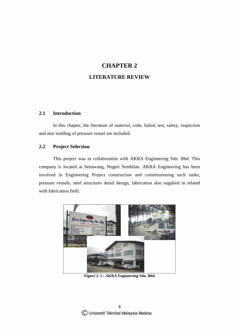
2.2 Project Selection
This project was in collaboration with AKRA Engineering Sdn. Bhd. This
company is located at Senawang, Negeri Sembilan. AKRA Engineering has been
involved in Engineering Project construction and commissioning such tanks,
pressure vessels, steel structures detail design, fabrication also supplied in related
with fabrication field.
Figure 2. 1 : AKRA Engineering Sdn. Bhd
5
Title of this project was “Critical Quality (QA) and Quality control (QC)
Process Procedure in Pressure Vessel Fabrication”, where this project are made in
term of to implement quality assurance (QA) and quality control (QC) process in
manufacturing pressure vessel and also to fabricate an air receiver of pressure vessel
comply with American Society of Mechanical Engineers VIII (ASME) Boiler and
Pressure Vessel Code (Division 1).
.
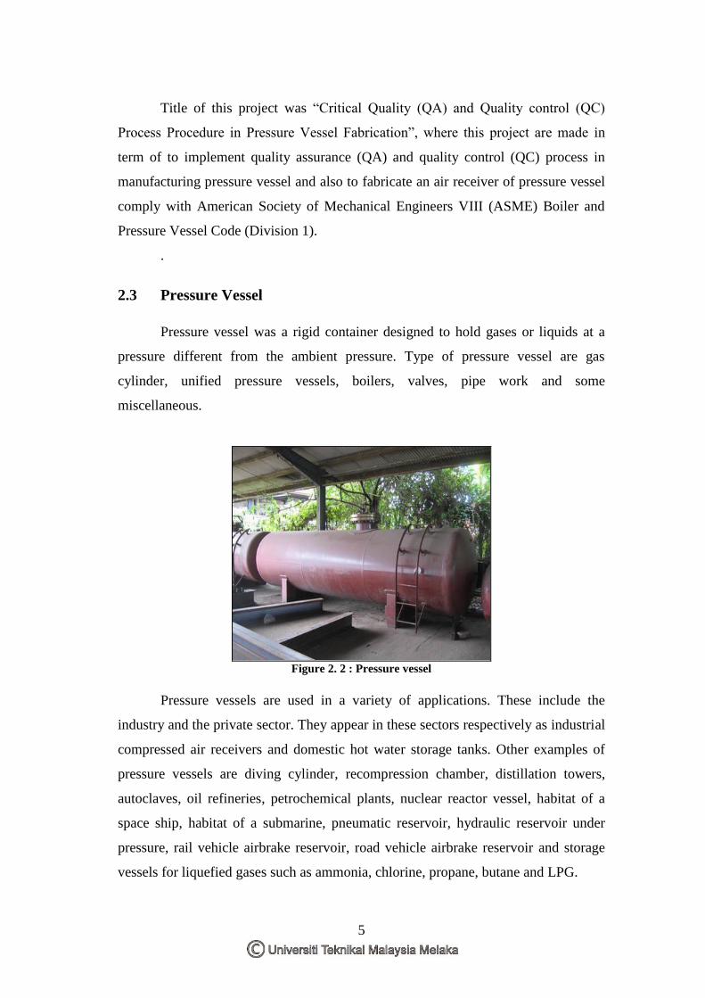
2.3 Pressure Vessel
Pressure vessel was a rigid container designed to hold gases or liquids at a
pressure different from the ambient pressure. Type of pressure vessel are gas
cylinder, unified pressure vessels, boilers, valves, pipe work and some
miscellaneous.
Figure 2. 2 : Pressure vessel
Pressure vessels are used in a variety of applications. These include the
industry and the private sector. They appear in these sectors respectively as industrial
compressed air receivers and domestic hot water storage tanks. Other examples of
pressure vessels are diving cylinder, recompression chamber, distillation towers,
autoclaves, oil refineries, petrochemical plants, nuclear reactor vessel, habitat of a
space ship, habitat of a submarine, pneumatic reservoir, hydraulic reservoir under
pressure, rail vehicle airbrake reservoir, road vehicle airbrake reservoir and storage
vessels for liquefied gases such as ammonia, chlorine, propane, butane and LPG.
6
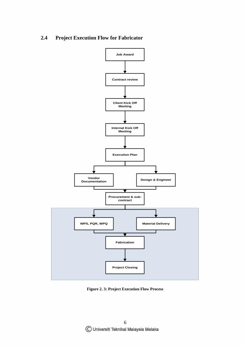
2.4 Project Execution Flow for Fabricator
Job Award
Vendor
Documentation Design & Engineer
Execution Plan
Internal Kick Off
Meeting
Client Kick Off
Meeting
Contract review
Material DeliveryWPS, PQR, WPQ
Procurement & sub-
contract
Fabrication
Project Closing
Figure 2. 3: Project Execution Flow Process
7
Job Award
Vendor
Documentation Design & Engineer
Execution Plan
Internal Kick Off
Meeting
Client Kick Off
Meeting
Contract review
Procurement & sub-
contract
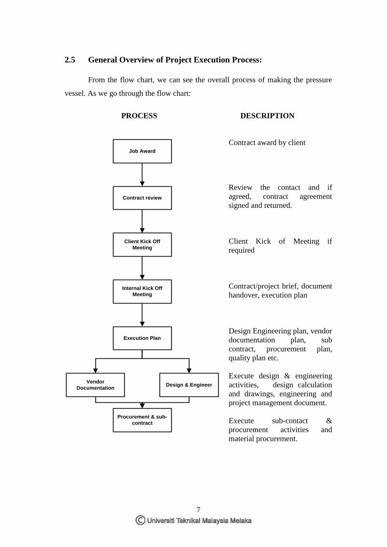
2.5 General Overview of Project Execution Process:
From the flow chart, we can see the overall process of making the pressure
vessel. As we go through the flow chart:
PROCESS DESCRIPTION
Contract award by client
Review the contact and if
agreed, contract agreement
signed and returned.
Client Kick of Meeting if
required
Contract/project brief, document
handover, execution plan
Design Engineering plan, vendor
documentation plan, sub
contract, procurement plan,
quality plan etc.
Execute design & engineering
activities, design calculation
and drawings, engineering and
project management document.
Execute sub-contact &
procurement activities and
material procurement.
8
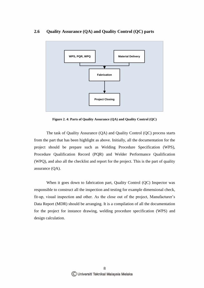
2.6 Quality Assurance (QA) and Quality Control (QC) parts
Material DeliveryWPS, PQR, WPQ
Fabrication
Project Closing
Figure 2. 4: Parts of Quality Assurance (QA) and Quality Control (QC)
The task of Quality Assurance (QA) and Quality Control (QC) process starts
from the part that has been highlight as above. Initially, all the documentation for the
project should be prepare such as Welding Procedure Specification (WPS),
Procedure Qualification Record (PQR) and Welder Performance Qualification
(WPQ), and also all the checklist and report for the project. This is the part of quality
assurance (QA).
When it goes down to fabrication part, Quality Control (QC) Inspector was
responsible to construct all the inspection and testing for example dimensional check,
fit-up, visual inspection and other. As the close out of the project, Manufacturer’s
Data Report (MDR) should be arranging. It is a compilation of all the documentation
for the project for instance drawing, welding procedure specification (WPS) and
design calculation.