Wheel over point mathematical model
14
Ocean Systems Engineering, Vol. 11, No. 3 (2021) 203-216 https://doi.org/10.12989/ose.2021.11.3.203 203 Copyright © 2021 Techno-Press, Ltd. http://www.techno-press.org/?journal=ose&subpage=7 ISSN: 2093-6702 (Print), 2093-677X (Online) Wheel over point mathematical model Amir Syawal Kamis * 1,2 , Ahmad Faizal Ahmad Fuad 2a , Azmirul Ashaari 3b and Che Wan Mohd Noor 4c 1 Rating Programs, Akademi Laut Malaysia, BT 30 Kg Tg Dahan, 78200 Kuala Sungai Baru Melaka, Malaysia 2 Faculty of Maritime Studies, Universiti Malaysia Terengganu, 21030 Kuala Terengganu, Terengganu, Malaysia 3 Azman Hashim International Business School, Universiti Teknologi Malaysia, Jalan Bertingkat Skudai, 81310 Johor Bahru, Johor, Malaysia 4 Faculty of Ocean Engineering Technology and Informatics, Universiti Malaysia Terengganu, 21030 Kuala Terengganu, Terengganu, Malaysia (Received April 11, 2021, Revised August 20, 2021, Accepted August 25, 2021) Abstract. This research proposes an improved mathematical model which can be used to calculate wheel over point (WOP) for a ship's route optimisation. WOP is a marking made on the charted course to demonstrate where the ship must initiate the course alteration to guarantee that it follows the route. The advance transfer technique (ATT) was used to determine WOP. Through practical exercise, two gaps were identified in ATT. From there, an improved mathematical model, namely ATMM, were developed. A preliminary manoeuvring analysis was then carried out in this study using a ship simulator for ATMM and the existing ATT. Then, the cross-track distance produced by both methods were compared to verify the difference. It was found that the ATMM produced better result in maintaining a ship on its course. This research's mathematical model is expected to be used onboard ship and used in the Electronic Chart Display and Information System to aid navigator in making more effective course alteration. Keywords: cross track distance; manoeuvring analysis; passage planning; ship simulation; wheel over point 1. Introduction It is essential for a ship to navigate by following one course line to another course line connected by waypoints (WPT), according to the ship's bridge team's agreed passage plan (Lušić et al. 2014, Skora and Wolski 2016). As shown in Fig. 1, the charted course is the course line drawn on the navigational chart connected by waypoints (ICS 2016, IMO 1999). WPT is where two different course lines are connected (ICS 2016, Skora and Wolski 2016, Swift 2018). When changing a course, alteration needs to be carried out at an ample distance, otherwise, the ship can overshoot from the track (Vujičić et al. 2018), which can result in a cross-track distance (XTD) (Lekkas and Fossen Corresponding author, Student, E-mail: [email protected] a Ph.D., E-mail: [email protected] b Ph.D., E-mail: [email protected] c Ph.D., E-mail: [email protected]
Transcript of Wheel over point mathematical model
Ocean Systems Engineering, Vol. 11, No. 3 (2021) 203-216
https://doi.org/10.12989/ose.2021.11.3.203 203
Copyright © 2021 Techno-Press, Ltd.
http://www.techno-press.org/?journal=ose&subpage=7 ISSN: 2093-6702 (Print), 2093-677X (Online)
Wheel over point mathematical model
Amir Syawal Kamis*1,2, Ahmad Faizal Ahmad Fuad2a,
Azmirul Ashaari3b and Che Wan Mohd Noor4c 1Rating Programs, Akademi Laut Malaysia, BT 30 Kg Tg Dahan, 78200 Kuala Sungai Baru Melaka, Malaysia
2Faculty of Maritime Studies, Universiti Malaysia Terengganu, 21030 Kuala Terengganu, Terengganu, Malaysia
3Azman Hashim International Business School, Universiti Teknologi Malaysia, Jalan Bertingkat Skudai, 81310 Johor Bahru, Johor, Malaysia
4Faculty of Ocean Engineering Technology and Informatics, Universiti Malaysia Terengganu, 21030 Kuala Terengganu, Terengganu, Malaysia
(Received April 11, 2021, Revised August 20, 2021, Accepted August 25, 2021)
Abstract. This research proposes an improved mathematical model which can be used to calculate wheel over point (WOP) for a ship's route optimisation. WOP is a marking made on the charted course to demonstrate where the ship must initiate the course alteration to guarantee that it follows the route. The advance transfer technique (ATT) was used to determine WOP. Through practical exercise, two gaps were identified in ATT. From there, an improved mathematical model, namely ATMM, were developed. A preliminary manoeuvring analysis was then carried out in this study using a ship simulator for ATMM and the existing ATT. Then, the cross-track distance produced by both methods were compared to verify the difference. It was found that the ATMM produced better result in maintaining a ship on its course. This research's mathematical model is expected to be used onboard ship and used in the Electronic Chart Display and Information System to aid navigator in making more effective course alteration.
Keywords: cross track distance; manoeuvring analysis; passage planning; ship simulation; wheel over
point
1. Introduction
It is essential for a ship to navigate by following one course line to another course line connected
by waypoints (WPT), according to the ship's bridge team's agreed passage plan (Lušić et al. 2014,
Skora and Wolski 2016). As shown in Fig. 1, the charted course is the course line drawn on the
navigational chart connected by waypoints (ICS 2016, IMO 1999). WPT is where two different
course lines are connected (ICS 2016, Skora and Wolski 2016, Swift 2018). When changing a course,
alteration needs to be carried out at an ample distance, otherwise, the ship can overshoot from the
track (Vujičić et al. 2018), which can result in a cross-track distance (XTD) (Lekkas and Fossen
Corresponding author, Student, E-mail: [email protected] a Ph.D., E-mail: [email protected] b Ph.D., E-mail: [email protected] c Ph.D., E-mail: [email protected]

Amir Syawal Kamis, Ahmad Faizal Ahmad Fuad, Azmirul Ashaari and Che Wan Mohd Noor
Fig. 1 Illustration for a charted course, WPT, and XTD
Table 1 WOP distance from WPT
Situation Change of course (θ) Advance (dadv) Transfer (dtrs) dCG-WPT
1 20 0.24 0.108 - 0.057
2 50 0.24 0.108 0.149
2014). The cross-track distance can bring a ship closer to land and expose the ship to danger (Briggs
et al. 2003, Kristić et al. 2020). Thus, a wheel over point (WOP) or altering course (AC) position
needs to be marked on the charted course as an indication of the point of alteration (Georgiana and
Stefan 2010, Rutkowski 2018).
Although the purpose is the same, WOP and AC have slightly different definitions. WOP is a
point where the rudder is set at maximum rudder angle (Anwar 2015), while AC position can be
executed at any rudder angle for an alteration of course (ICS 2016). Both techniques contribute to
energy efficiency in terms of fuel consumption (Chaal 2018) as they optimise the vessel’s voyage in
maintaining optimum route (Lu et al. 2015, Tiwari et al. 2020). Most importantly, these techniques
can ensure the safety of the ship's navigation by maintaining the ship on its track (Vujičić et al. 2018).
1.1 The problem statement and research aim
The advance transfer technique (ATT) is a technique used to find WOP (Anwar 2015). To further
understand the ATT usage, a practical exercise was carried out on a navigational chart in this study.
During the practical session, two problems were identified.
1.1.1 The first observation – Negative value for alteration less than 20 The formula for ATT that was proposed by Anwar (2015) is shown in (2). Below is an example
of the calculation of WOP for 20 and 50 course alteration.
204

Wheel over point mathematical model
Fig. 2 Advance transfer technique principle (Anwar 2015)
The negative value of WOP for situation 1 in Table 1 implies that the ship has to make the course
alteration 0.057 nm after WPT, which means that the ship has overshot the planned track.
1.1.2 Second observation – The final heading of the ship does not match the charted course
The principle of the technique works as shown in Fig. 2. It can be observed that the final heading
of the ship is 090°T, which do not match the 045°T desired course. This can cause a second overshoot.
2. Methodology
The research started with a review on the ATT to further understand WOP's concept. Through the
review, a research gap was identified and then an approach of restructuring the application of
manoeuvring characteristic in determining WOP was made. From there, a new advance transfer
mathematical model (ATMM) was developed.
After developing the mathematical model, both ATT and ATMM were tested against observations
from the physical system that they represented, which in this case, was a ship simulator. This process
is usually called validation (Voit and Voit 2020).
Using the Wartsila ship simulator, a manoeuvring analysis was carried out to test both methods
to validate the model by determining its impact on the cross-track distance (XTD). When two models
of the same system are available, researchers may want to compare them to choose one for future
use (Voit and Voit 2020). Therefore, after simulation analysis was carried out, XTD results for both
methods were compared to determine whether ATMM is better than ATT in determining WOP.
2.1 Review on advance transfer technique (ATT)
The manoeuvring characteristic of a vessel is subjected to the rudder angle ordered for a
205

Amir Syawal Kamis, Ahmad Faizal Ahmad Fuad, Azmirul Ashaari and Che Wan Mohd Noor
particular manoeuvre (Kim et al. 2005). A constant turning circle can be achieved by fixing the
ship’s rudder at a certain angle (Drachev 2012). Upon ship delivery, a sea trial manoeuvre will be
carried out, resulting in a specific manoeuvring characteristic for that ship where manoeuvring
details are recorded, including a turning circle for every particular rudder angle (Duman and Bal
2017, IMO 2002).
This method of fixing rudder at hard over rudder angle during turning is also known as the
advance transfer technique (Anwar 2015, Lušić et al. 2014), and it is widely used while navigating
in inland water and during pilotage. Other techniques for determining WOP, such as constant radius
turn (CRT) and constant rate of turn (CROT), require the vessel's speed as a variable in their
respective formulas (Jithin 2019). However, as the turning circle's characteristic is unaffected by the
vessel's speed (Kim et al. 2005), ATT allows WOP to be calculated without having to include the
ship's speed, which can be seen in equation (2). In open sea navigation, the speed of a ship can be
considered as constant and predictable according to the previous voyage’s service speed. Thus, it is
possible for any technique to be applied under such condition. Comparatively, in inland water, the
ship’s speed is frequently adjusted depending on the traffic density, the state of visibility, water depth,
manoeuvrability, navigation hazards (House 2004a), and as per the pilot’s advice (TTEG 2008). As
a result, CRT and CROT are difficult to be used during navigation in inland water and pilotage. For
this reason, ATT is preferable in such situations.
The basic concept of determining WOP can be derived from a few methods and techniques
(Anwar 2015, Georgiana and Stefan 2010, Jithin 2019, Schlemmer 2020); however, this study
focuses only on the identification of the ship’s WOP according to the advance transfer technique by
Anwar (2015), which requires two variables from the manoeuvring characteristic as shown in Fig.
3, namely 1) advance and 2) transfer distance, hence its name.
Fig. 3 Typical manoeuvring characteristic of a ship (ITTC 2002)
206
Wheel over point mathematical model
Advance is the distance covered during the forward motion of the ship from the point that the
vessel initiates the turn and transfer is defined as the distance covered when the vessel moves
perpendicular to the fore and aft line at the commencement of the turn (House 2004b). In other words,
advance and transfer distance can be measured from the moment the vessel initiates the turn by hard
over the rudder until the ship’s heading changes by 90 from the initial heading, where the distance
of advance is on the X0 axis and the distance of transfer is on the Y0 axis, as shown in Figure 3 (ITTC
2002). Both distances are measured by referring to the positioning of the ship’s centre of gravity
(CG) (ITTC 2002).
The advance and transfer distance are usually expressed in nautical miles (nm) and they can be
extracted from the manoeuvring characteristic. The usage of the aforementioned information to
determine the WOP is as explained below.
With references to Figs. 4-6, the symbols abbreviations used for explaining the formula are as
follows:
𝑑𝑎𝑑𝑣 = Advance distance from manoeuvring characteristic
𝑑𝑡𝑟𝑠 = Transfer distance from manoeuvring characteristic
𝑑𝐶𝐺−𝑊𝑃𝑇 = Distance from ship’s centre of gravity to WPT
𝑑𝑊𝑂𝑃 = Distance of WOP’ from WPT
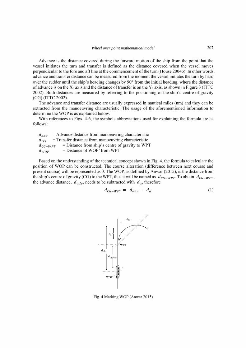
Based on the understanding of the technical concept shown in Fig. 4, the formula to calculate the
position of WOP can be constructed. The course alteration (difference between next course and
present course) will be represented as θ. The WOP, as defined by Anwar (2015), is the distance from
the ship’s centre of gravity (CG) to the WPT, thus it will be named as 𝑑𝐶𝐺−𝑊𝑃𝑇. To obtain 𝑑𝐶𝐺−𝑊𝑃𝑇,
the advance distance, 𝑑𝑎𝑑𝑣, needs to be subtracted with 𝑑𝑎, therefore
𝑑𝐶𝐺−𝑊𝑃𝑇 = 𝑑𝑎𝑑𝑣 − 𝑑𝑎 (1)
Fig. 4 Marking WOP (Anwar 2015)
207

Amir Syawal Kamis, Ahmad Faizal Ahmad Fuad, Azmirul Ashaari and Che Wan Mohd Noor
Fig. 5 This study’s concept (ship’s heading and course are the same at the end of alteration)
𝑑𝑎 can be obtained by utilising the tangent rule as follows
𝑡𝑎𝑛 𝜃 =𝑑𝑡𝑟𝑠
𝑑𝑎
𝑑𝑎 =𝑑𝑡𝑟𝑠
𝑡𝑎𝑛 𝜃
Hence, the formula of advance transfer technique (Anwar 2015) is obtained as below
𝑑𝐶𝐺−𝑊𝑃𝑇 = 𝑑𝑎𝑑𝑣 −𝑑𝑡𝑟𝑠
𝑡𝑎𝑛 𝜃 (2)
2.2 Restructure the application of manoeuvring characteristic
To improve the usage of advance and transfer distance in determining WOP, this study intends to
improvise the ATT technique so that the ship’s final course matches the charted course in the passage
plan.
Therefore, to match the final course with the ship’s heading, this research intends to redesign the
technique as shown in Fig. 5 to ensure that the final heading of the ship will match the desired next
course.
2.3 Development of research mathematical model (ATMM)
The mathematical model can be constructed from the existing equation that is published in the
related study (Voit and Voit 2020). Therefore, the ATT equation by Anwar (2015) can be used as the
208

Wheel over point mathematical model
Fig. 6 Distribution details
foundation of the mathematical model, which will be constructed for the calculation of the WOP
position. Fig. 6 is constructed according to the generic diagram of a ship turning circle and it will be
used to assist the explanation on the development of ATMM.
As shown in Fig. 6, the development of ATMM will also include the distance from the ship’s
bridge to the ship’s centre of gravity (CG). Therefore, in addition to (1), the distance of WOP’ from
WPT, also known as 𝑑𝑊𝑂𝑃, will consist of 1) 𝑑𝐶𝐺−𝑊𝑃𝑇 and 2) 𝑑𝑐, hence
𝑑𝑊𝑂𝑃 = 𝑑𝐶𝐺−𝑊𝑃𝑇 + 𝑑𝑐
With reference to the existing ATT formula in (1), 𝑑𝐶𝐺−𝑊𝑃𝑇 = 𝑑𝑎𝑑𝑣 − 𝑑𝑎, the equation can
be re-written as
𝑑𝑊𝑂𝑃 = 𝑑𝑎𝑑𝑣 − 𝑑𝑎 + 𝑑𝑐 (3)
The next step is to find the value of 𝑑𝑎 and 𝑑𝑐.
To find 𝑑𝑎, the following trigonometry function can be used
𝑡𝑎𝑛 𝜃 = 𝑄𝑅
𝑑𝑎
𝑑𝑎 =𝑄𝑅
𝑡𝑎𝑛 𝜃 (4)
To get QR, subtract RS from QS. QS is equal to 𝑑𝑡𝑟𝑠. For now, RS will be represented as 𝑑𝑏 as
shown in Fig. 6. Thus, 𝑄𝑅 = 𝑑𝑡𝑟𝑠 − 𝑑𝑏. Consequently, (4) can be written as follows
209

Amir Syawal Kamis, Ahmad Faizal Ahmad Fuad, Azmirul Ashaari and Che Wan Mohd Noor
𝑑𝑎 =𝑑𝑡𝑟𝑠−𝑑𝑏
𝑡𝑎𝑛 𝜃 (5)
ROS is a right-angled triangle; therefore, the value of 𝑑𝑏 can be obtained by utilising the
trigonometry tangent function
𝑡𝑎𝑛 ∠𝑅𝑂𝑆 =𝑑𝑏
𝑑𝑡𝑟𝑠
𝑑𝑏 = 𝑑𝑡𝑟𝑠 ∙ 𝑡𝑎𝑛 ∠𝑅𝑂𝑆 (6)
To determine ∠ROS, first, it needs to be noted that TU is a tangent line to OP, TU OP, which
makes UPO equal to 90, ∟𝑈𝑃𝑂 = 90. According to the rules of a triangle, the total inner angle
of a triangle must be equal to 180, PUO = 180. The total inner angle of triangle PUO is the sum
value of ∠UOP, ∟𝑈𝑃𝑂, and ∠𝑃𝑈𝑂. This can also be written as
∠𝑈𝑂𝑃 + ∟𝑈𝑃𝑂 + ∠𝑃𝑈𝑂 = 𝑃𝑈𝑂
∠𝑈𝑂𝑃 + 90 + 𝜃 = 180°
∠𝑈𝑂𝑃 = 180 − 90 − 𝜃
∠𝑈𝑂𝑃 = 90 − 𝜃
According to the rule of the tangent to a circle, RP and RS will be the same, RP = RS , since both distances are tangent to the circle. Thus, the angle of POR and ROS are also the same,
∠POR = ∠ROS . Hence, ∠𝑅𝑂𝑆 is half of the value of ∠𝑃𝑂𝑆 . For this reason, ∠𝑅𝑂𝑆 can be
expressed as
∠𝑅𝑂𝑆 = ∠𝑃𝑂𝑆
2
∠𝑅𝑂𝑆 = 90°−𝜃
2 (7)
With reference to (6) and the input from (7), the following is obtained
𝑑𝑏 = 𝑑𝑡𝑟𝑠 ∙ 𝑡𝑎𝑛 ∠𝑅𝑂𝑆
𝑑𝑏 = 𝑑𝑡𝑟𝑠 ∙ 𝑡𝑎𝑛 (90°−𝜃
2) (8)
Inserting (8) into (5), 𝑑𝑎 can be obtained as
𝑑𝑎 = 𝑑𝑡𝑟𝑠− 𝑑𝑡𝑟𝑠 ∙𝑡𝑎𝑛(
90°−𝜃
2)
𝑡𝑎𝑛 𝜃 (9)
A turning circle is constructed with reference to the ship’s centre of gravity (CG) (ITTC 2002).
For this reason, Anwar (2015) used the CG to locate the WOP. However, while navigating, the ship’s
position is monitored using the global navigation satellite system (GNSS), which is located at the
ship’s bridge. To be precise, it is located at the location where the GNSS antenna is mounted.
Therefore, the actual alteration shall be carried out by monitoring the GNSS position while taking
into account the moment when the CG will be at the WOP position. Thus, the actual WOP marked
on the chart shall include the distance between the bridge, hence 𝑑𝐶𝐺 = 𝑑𝑐, and this is applied as
follows.
210
Wheel over point mathematical model
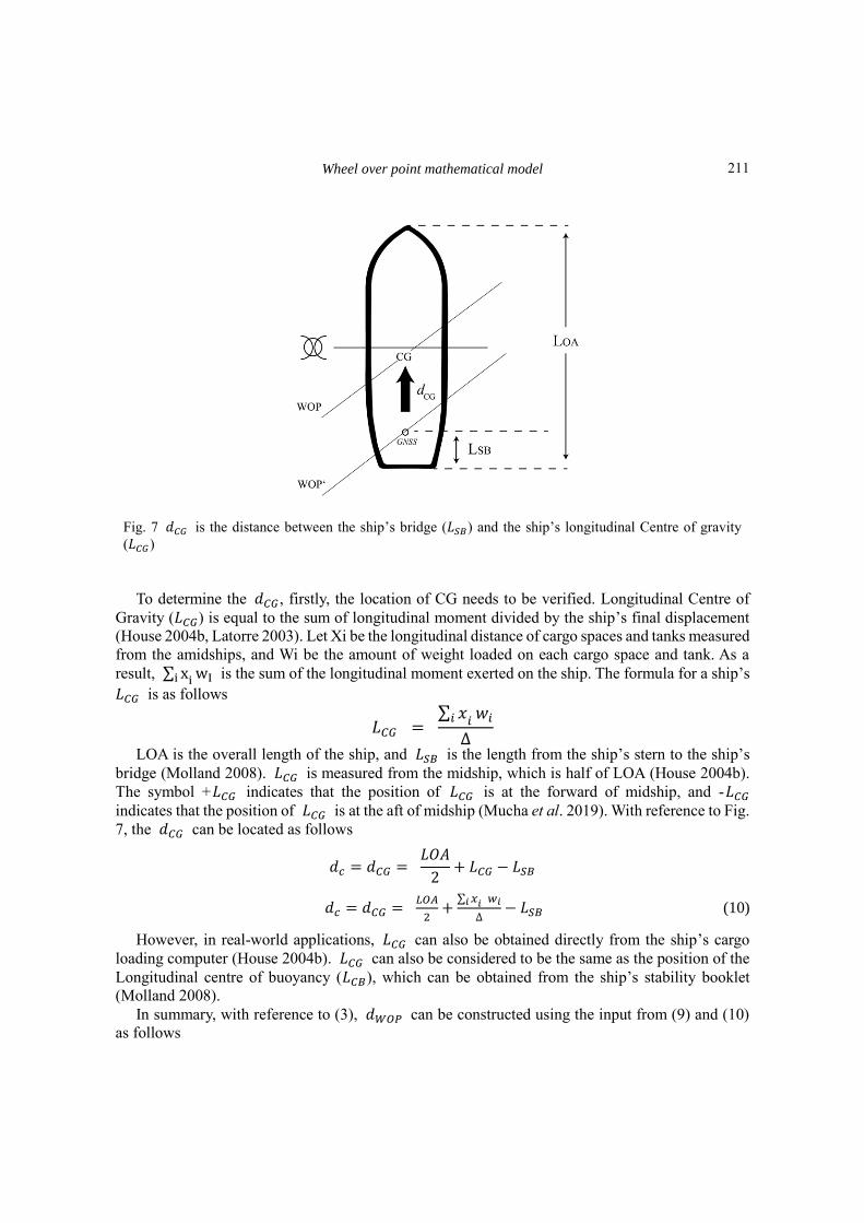
Fig. 7 𝑑𝐶𝐺 is the distance between the ship’s bridge (𝐿𝑆𝐵) and the ship’s longitudinal Centre of gravity
(𝐿𝐶𝐺)
To determine the 𝑑𝐶𝐺, firstly, the location of CG needs to be verified. Longitudinal Centre of
Gravity (𝐿𝐶𝐺) is equal to the sum of longitudinal moment divided by the ship’s final displacement
(House 2004b, Latorre 2003). Let Xi be the longitudinal distance of cargo spaces and tanks measured
from the amidships, and Wi be the amount of weight loaded on each cargo space and tank. As a
result, ∑ xi i wI is the sum of the longitudinal moment exerted on the ship. The formula for a ship’s
𝐿𝐶𝐺 is as follows
𝐿𝐶𝐺 = ∑ 𝑥𝑖 𝑖
𝑤𝑖
∆
LOA is the overall length of the ship, and 𝐿𝑆𝐵 is the length from the ship’s stern to the ship’s
bridge (Molland 2008). 𝐿𝐶𝐺 is measured from the midship, which is half of LOA (House 2004b).
The symbol +𝐿𝐶𝐺 indicates that the position of 𝐿𝐶𝐺 is at the forward of midship, and -𝐿𝐶𝐺
indicates that the position of 𝐿𝐶𝐺 is at the aft of midship (Mucha et al. 2019). With reference to Fig.
7, the 𝑑𝐶𝐺 can be located as follows
𝑑𝑐 = 𝑑𝐶𝐺 = 𝐿𝑂𝐴
2+ 𝐿𝐶𝐺 − 𝐿𝑆𝐵
𝑑𝑐 = 𝑑𝐶𝐺 = 𝐿𝑂𝐴
2+
∑ 𝑥𝑖 𝑖 𝑤𝑖
∆− 𝐿𝑆𝐵 (10)
However, in real-world applications, 𝐿𝐶𝐺 can also be obtained directly from the ship’s cargo
loading computer (House 2004b). 𝐿𝐶𝐺 can also be considered to be the same as the position of the
Longitudinal centre of buoyancy (𝐿𝐶𝐵 ), which can be obtained from the ship’s stability booklet
(Molland 2008).
In summary, with reference to (3), 𝑑𝑊𝑂𝑃 can be constructed using the input from (9) and (10)
as follows
211

Amir Syawal Kamis, Ahmad Faizal Ahmad Fuad, Azmirul Ashaari and Che Wan Mohd Noor
𝑑𝑊𝑂𝑃 = 𝑑𝑎𝑑𝑣 − 𝑑𝑎 + 𝑑𝑐
𝑑𝑊𝑂𝑃 = 𝑑𝑎𝑑𝑣 − (9) + (10)
𝑑𝑊𝑂𝑃 = 𝑑𝑎𝑑𝑣 − (𝑑𝑡𝑟𝑠− 𝑑𝑡𝑟𝑠 .𝑡𝑎𝑛(
90°−𝜃
2)
𝑡𝑎𝑛 𝜃) + (
𝐿𝑂𝐴
2+
∑ 𝑥𝑖 𝑖 𝑤𝑖
∆− 𝐿𝑆𝐵) (11)
3. Simulator test
A ship simulator is a dependable piece of technology that can be used to aid in the study on
manoeuvring (Duarte et al. 2016). Additionally, researchers utilise it to analyse the effects of shallow
water and bank on a ship's turning circle (Du et al. 2018, Duarte et al. 2016, Kobylinski 2012, Mucha
et al. 2019).
In this study, the developed ATMM was evaluated using the Wartsila Ship Simulator. The
Wartsila Ship Simulator focuses on supplying main modules with new technologies to enable
specialised training applications. It offers actual navigation simulation for more than 100 ship types
and can configure the sea conditions according to user requirements (Wärtsilä 2020).
There are three major techniques that can be used to anticipate the manoeuvrability of a vessel
and consequently validate the vessel's turning circle (IMO 2002, Yiew et al. 2019). The first one is
by performing simulations using computational fluid dynamics (CFD) to parameterise the various
hydrodynamic coefficients, while taking into account the vessel’s 6 degree-of-freedom (6-DOF)
motions and control responses (Taimuri et al. 2020). The second method is through the assessment
of the hydrodynamic derivatives using manoeuvring models and system identification methods
(Yiew et al. 2019). Finally, the third technique is through a full-scale trial method whereby an actual
ship is manoeuvred to obtain its turning circle (IMO 2002). This study used the full-scale trial
method. However, instead of using an actual ship, the manoeuvring was carried out using a ship
simulator.
The simulation was performed using a bulk carrier type of ship with a total length of 182.9 m
and a width of 22.6 m. The ship was in laden condition, with a displacement of 33089 tonnes and a
10.7m draught. The simulator recorded that the advance distance for this ship was 0.283 nm for port
turning circle and 0.296 nm for starboard turning circle. On the other hand, the transfer distance was
0.137 nm and 0.144 nm for port and starboard turning circle, respectively. The ship 𝐿𝐶𝐺 was 0, and
the 𝐿𝑆𝐵 was 30.5 m. Using Eq. (10), the 𝑑𝐶𝐺 was calculated to be 0.0329 nm.
For the manoeuvring simulation, two charted routes were created on the simulator. One course
was for port course alteration and another one was for starboard course alteration, which can be seen
in Figs. 8 and 9. The WOPs were calculated using the ATT formula in Eq. (2) and the ATMM formula
in Eq. (11), and recorded in Table 2 below. Then, the simulations were carried out by manoeuvring
Table 2 WOP calculated using ATT and ATMM equation
Side 𝜃 𝑑𝑎𝑑𝑣
(nm) 𝑑𝑡𝑟𝑠 (nm) 𝑑𝐶𝐺 (nm)
WOP
ATT ATMM
PORT 30 0.283 0.137 0.0329 0.046 0.216
STBD 30 0.296 0.144 0.0329 0.047 0.223
212

Wheel over point mathematical model
Using ATT method Using the ATMM
Fig. 8 Port alteration
Fig. 9 Starboard alteration
the ship on the charted course. When the ship arrived at the WOP, the course alterations were
executed. The same process was repeated four times where two manoeuvring operations were
carried out with reference to the WOP calculated using ATT while another two operations were
executed based on the WOP calculated using ATMM. During the analysis, the XTD were carefully
monitored.
4. Results and discussion
It is noteworthy to emphasise again that the objective of the analysis is to build a mathematical
WOP model that improves course tracking by monitoring the XTD. The simulation results are as
follows.
With reference to Fig. 8, when applying the ATT for port alteration, XTD is found to be 170 m
to the starboard side of the vessel's track. Meanwhile, alteration to port using the ATMM successfully
reduces the XTD to 12 m to the vessel's track.
With reference to Fig. 9, the same simulation is applied to starboard alteration, where alteration
using ATT results in 181 m to port of the vessel's track. However, after applying the ATMM, the
213

Amir Syawal Kamis, Ahmad Faizal Ahmad Fuad, Azmirul Ashaari and Che Wan Mohd Noor
XTD is reduced to 17 m to the vessel's track.
It can be inferred that ATMM provides improved XTD in terms of its distance to the charted
course.
5. Conclusions
The ship must remain on the expected course line because of many reasons. Other than reducing
fuel consumption, the most significant reason is that it can keep the vessel safe as many instances of
collisions arise due to XTD ignorance (Kristić et al. 2020). After all, safety is the priority for a ship's
operation (Kamis et al. 2020). It was observed that the ATT procedure could be further enhanced
after studying and analysing the ATT process of evaluating WOP. A mathematical model, namely
ATMM, was successfully developed and tested through manoeuvring simulation using the Wartsila
ship simulator.
Contribution
It can be inferred that the ATMM built in this study significantly reduces the XTD as one of the
techniques for deciding WOP. However, the simulation study is still at preliminary stages and further
manoeuvring analysis will be carried out using various type of cargo ships.
Few cases of accidents had happened due to a lack of knowledge regarding WOP (TAIC 2016).
With ATMM used as an algorithm in the ECDIS, it can automatically generate the WOP for each
course alteration for passage planning to provide extra safety measures in case navigators are
unaware of it.
Suggestion for future research
Additional tests using a different type of ship and various turning angles can be carried out to
verify the mathematical model's effectiveness. Other than that, ensuring that the ship is staying on
the course line will help to minimise fuel consumption in this study. Perhaps this study can be
expanded to evaluate the effect on energy efficiency due to the reduction of XTD.
Acknowledgements
This research was supported by the Maritime Simulation Communication Center, Akademi Laut
Malaysia. The research presented in the manuscript did not receive any external funding.
References Anwar, N. (2015), Navigation Advanced Mates/Masters (2nd Ed.), Weatherby Seamanship International, a
Division of Witherbys Publishing Group Limited. https://www.witherbyseamanship.com/navigation-
advanced-for-matesmasters-2nd-edition.html.
Briggs, M.J., Borgman, L.E. and Bratteland, E. (2003), “Probability assessment for deep-draft navigation
channel design”, Coast. Eng., 48(1), 29-50. https://doi.org/10.1016/S0378-3839(02)00159-X.
214

Wheel over point mathematical model
Chaal, M. (2018), Ship Operational Performance Modelling for Voyage Optimization through Fuel
Consumption Minimization [World Maritime University Dissertations].
https://commons.wmu.se/all_dissertations/633.
Drachev, V.N. (2012), Calculating Wheel-Over Point, Asia-Pacific Journal of Marine Science&Education,
2(1), 27–46.
Du, P., Ouahsine, A. and Sergent, P. (2018), “Influences of the separation distance, ship speed and channel
dimension on ship maneuverability in a confined waterway”, Comptes Rendus - Mecanique, 346(5), 390-
401. https://doi.org/10.1016/j.crme.2018.01.005.
Duarte, H.O., Droguett, E.L., Martins, M.R., Lutzhoft, M., Pereira, P.S. and Lloyd, J. (2016), “Review of
practical aspects of shallow water and bank effects”, T. Roy. Inst.Naval Archit. Part A: Int. J. Mar. Eng.,
158, 177-186. https://doi.org/10.3940/rina.ijme.2016.a3.362.
Duman, S. and Bal, S. (2017), “Prediction of the turning and zig-zag maneuvering performance of a surface
combatant with URANS”, Ocean Syst. Eng., 7(4), 435-460.
Georgiana, S. and Stefan, G. (2010), “Planning and execution of blind pilotage and anchorage”, Constanta
Maritime Univ. Annal., 14(2), 35-40. http://www2.cmu-edu.eu/annals/on-line-journal/
House, D.J. (2004a), Preventing Collisions at Sea. In Seamanship Techniques: Vol. Consolidat, 395–444.
https://doi.org/10.1016/B978-075066315-1/50017-8.
House, D.J. (2004b), The Ship. In Seamanship Techniques, 1-27.https://doi.org/10.1016/B978-075066315-
1/50005-1.
ICS. (2016), Bridge Procedure Guide (5th Ed.), Marisec Publications. https://www.academia.edu/29814888
IMO. (1999), Guidelines for voyage planning - Resolution A.893(21) (Vol. 893, Issue November).
IMO. (2002), Standards For Ship Manoeuvrability. In MSC Resolution: Vol. 137(76) (Issue December).
ITTC. (2002), Full Scale Measurements Manoeuvrability Full Scale Manoeuvring Trials Procedure. In ITTC
- Recommended procedure.
Jithin. (2019), Constant Radius Turn | Knowledge Of Sea. Navigation. https://knowledgeofsea.com/constant-
radius-turn/
Kamis, A.S., Ahmad Fuad, A.F., Mohd Fadzil, M.N. and Saadon, S.I. (2020), “The impact of basic training on
seafarers’ safety knowledge, attitude and behaviour”, J. Sustainab. Sci. Management, 15(6), 137-158.
https://doi.org/10.46754/jbsd.2020.08.012.
Kim, M.S., Shin, H.O., Kang, K.M. and Kim, M.S. (2005), “Variation of the turning circle by the rudder Angle
and the ship’s speed-mainly on the training ship KAYA”, Bull. Korean Soc. Fisheries Technol., 41(2), 156-
164. https://doi.org/10.3796/KSFT.2005.41.2.156.
Kobylinski, L.K. (2012), “Capabilities of ship handling simulators to simulate shallow water, bank and canal
effects”, Navigational Syst. Simul., 5(2), 115-120. https://doi.org/10.1201/b11343-20.
Kristić, M., Žuškin, S., Brčić, D. andValčić, S. (2020), “Zone of confidence impact on cross track limit
determination in ECDIS passage planning”, J. Mar. Sci. Eng., 8(8). https://doi.org/10.3390/JMSE8080566.
Latorre, R. (2003), Naval Architecture, In Encyclopedia of Physical Science and Technology,. 105(1), 343-
360. https://doi.org/10.1016/B0-12-227410-5/00474-9.
Lekkas, A.M. and Fossen, T.I. (2014), “Minimization of cross-track and along-track errors for path tracking
of marine underactuated vehicles”, Proceedings of the 2014 European Control Conference, ECC 2014,
October 2015. https://doi.org/10.1109/ECC.2014.6862594.
Lu, R., Turan, O., Boulougouris, E., Banks, C. and Incecik, A. (2015), “A semi-empirical ship operational
performance prediction model for voyage optimization towards energy efficient shipping”, Ocean Eng., 110,
18-28. https://doi.org/10.1016/j.oceaneng.2015.07.042.
Lušić, Z., Kos, S. and Galić, S. (2014), “Standardisation of plotting courses and selecting turn points in
maritime navigation”, PROMET - Traffic&Transportation, 26(4), 313-322.
https://doi.org/10.7307/ptt.v26i4.1437.
Molland, A.F. (2008), The Maritime Engineering Reference Book. In The Maritime Engineering Reference
Book, https://doi.org/10.1016/B978-0-7506-8987-8.X0001-7.
Mucha, P., Dettmann, T., Ferrari, V. and el Moctar, O. (2019), “Experimental investigation of free-running
ship manoeuvers under extreme shallow water conditions”, Appl. Ocean Res., 83, 155-162.
215

Amir Syawal Kamis, Ahmad Faizal Ahmad Fuad, Azmirul Ashaari and Che Wan Mohd Noor
https://doi.org/10.1016/j.apor.2018.09.008.
Rutkowski, G. (2018), “ECDIS limitations, data reliability, alarm management and safety settings
recommended for passage planning and route monitoring on VLCC tankers”, T. Nav, the Int. J. Mar.
Navigation Saf. Sea T., 12(3), 483-490. https://doi.org/10.12716/1001.12.03.06.
Schlemmer, G. (2020), Blind pilotage techniques | Nautical Science Grade 12. https://maritimesa.org/nautical-
science-grade-12/2020/09/17/blind-bilotage-techniques.
Skora, K. and Wolski, A. (2016), “Voyage planning”, Sci. J. Silesian Univ. Technol. Series Transport, 92, 123-
128. https://doi.org/10.20858/sjsutst.2016.92.12.
Swift, A.J. (2018), Bridge team management: A practical guide (2nd Ed.), Nautical Institute.
TAIC. (2016), Final report MO-2016-202: Passenger ship, Azamara Quest , contact with Wheki Rock, Tory
Channel, 27 January 2016.
Taimuri, G., Matusiak, J., Mikkola, T., Kujala, P. andHirdaris, S. (2020), “A 6-DoF maneuvering model for
the rapid estimation of hydrodynamic actions in deep and shallow waters”, Ocean Eng., 218, 108103.
https://doi.org/10.1016/j.oceaneng.2020.108103.
Tiwari, K., Hariharan, K., And, T.V.R. and Krishnankutty, P. (2020), “Prediction of a research vessel
manoeuvring using numerical PMM and free running tests”, Ocean Syst. Eng., 10(3), 333-357.
https://doi.org/10.12989/OSE.2020.10.3.333.
TTEG. (2008), Guidelines on Voluntary Pilotage Services in The Straits of Malacca and Singapore (Issue
October). http://www.marine.gov.my/jlmv4/sites/default/files/ANNEX-U_13.1-
ANNEX_2_Guidelines_on_VPS_in_SOMS.pdf
Voit, E.O. and Voit, E.O. (2020), Introduction to Mathematical Modeling. A First Course in Systems Biology,
19-50. https://doi.org/10.4324/9780203702260-2.
Vujičić, S., Mohović, R. and Tomaš, I.Đ. (2018), “Methodology for controlling the ship’s path during the turn
in confined waterways”, Pomorstvo, 32(1), 28-35. https://doi.org/10.31217/p.32.1.2.
Wärtsilä. (2020), Simulation and Training Solutions. https://www.wartsila.com/docs/default-source/product-
files/optimise/simulation-and-training/navigational-simulators-brochure.pdf
Yiew, L.J., Jin, Y. and Magee, A.R. (2019), “On estimating the hydrodynamic coefficients and environmental
loads for a free-running vessel in waves”, J. Phys. Conference Series, 1357(1).
https://doi.org/10.1088/1742-6596/1357/1/012007.
MK
216