

Bahasa
Halaman
Undang-undang

67:1 (2014) 35–46 | www.jurnalteknologi.utm.my | eISSN 2180–3722 |
Full paper Jurnal
Teknologi
Modeling and Control of a Nonlinear Active Suspension Using Multi-Body Dynamics System Software M. Fahezal Ismaila*, Y. M. Samb, S. Sudinb, K. Pengc, M. Khairi Aripind
aIndustrial Automation Section, Universiti Kuala Lumpur Malaysia France Institute, 43650 Bdr.Baru Bangi, Selangor, Malaysia bFaculty of Electrical Engineering, Universiti Teknologi Malaysia, 81310 UTM Skudai, Johor, Malaysia cTemasek Laboratories, National University of Singapore, Singapore 117411, Singapore dFaculty of Electrical Engineering, Universiti Teknikal Malaysia Melaka, 76100 Durian Tunggal, Melaka, Malaysia *Corresponding author: [email protected]
Article history
Received :17 September 2013 Received in revised form :
26 December 2013
Accepted :30 January 2014
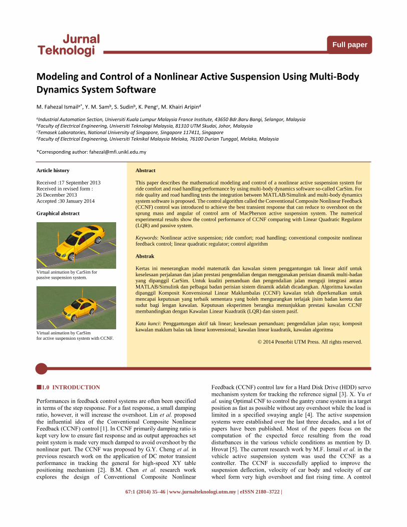
Graphical abstract
Virtual animation by CarSim for
passive suspension system.
Virtual animation by CarSim
for active suspension system with CCNF.
Abstract
This paper describes the mathematical modeling and control of a nonlinear active suspension system for ride comfort and road handling performance by using multi-body dynamics software so-called CarSim. For
ride quality and road handling tests the integration between MATLAB/Simulink and multi-body dynamics
system software is proposed. The control algorithm called the Conventional Composite Nonlinear Feedback (CCNF) control was introduced to achieve the best transient response that can reduce to overshoot on the
sprung mass and angular of control arm of MacPherson active suspension system. The numerical
experimental results show the control performance of CCNF comparing with Linear Quadratic Regulator (LQR) and passive system.
Keywords: Nonlinear active suspension; ride comfort; road handling; conventional composite nonlinear feedback control; linear quadratic regulator; control algorithm
Abstrak
Kertas ini menerangkan model matematik dan kawalan sistem penggantungan tak linear aktif untuk
keselesaan perjalanan dan jalan prestasi pengendalian dengan menggunakan perisian dinamik multi-badan yang dipanggil CarSim. Untuk kualiti pemanduan dan pengendalian jalan menguji integrasi antara
MATLAB/Simulink dan pelbagai badan perisian sistem dinamik adalah dicadangkan. Algoritma kawalan
dipanggil Komposit Konvensional Linear Maklumbalas (CCNF) kawalan telah diperkenalkan untuk mencapai keputusan yang terbaik sementara yang boleh mengurangkan terlajak jisim badan kereta dan
sudut bagi lengan kawalan. Keputusan eksperimen berangka menunjukkan prestasi kawalan CCNF
membandingkan dengan Kawalan Linear Kuadratik (LQR) dan sistem pasif.
Kata kunci: Penggantungan aktif tak linear; keselesaan pemanduan; pengendalian jalan raya; komposit
kawalan maklum balas tak linear konvensional; kawalan linear kuadratik, kawalan algoritma
© 2014 Penerbit UTM Press. All rights reserved.
1.0 INTRODUCTION
Performances in feedback control systems are often been specified
in terms of the step response. For a fast response, a small damping
ratio, however, it will increase the overshoot. Lin et al. proposed
the influential idea of the Conventional Composite Nonlinear
Feedback (CCNF) control [1]. In CCNF primarily damping ratio is
kept very low to ensure fast response and as output approaches set
point system is made very much damped to avoid overshoot by the
nonlinear part. The CCNF was proposed by G.Y. Cheng et al. in
previous research work on the application of DC motor transient
performance in tracking the general for high-speed XY table
positioning mechanism [2]. B.M. Chen et al. research work
explores the design of Conventional Composite Nonlinear
Feedback (CCNF) control law for a Hard Disk Drive (HDD) servo
mechanism system for tracking the reference signal [3]. X. Yu et
al. using Optimal CNF to control the gantry crane system in a target
position as fast as possible without any overshoot while the load is
limited in a specified swaying angle [4]. The active suspension
systems were established over the last three decades, and a lot of
papers have been published. Most of the papers focus on the
computation of the expected force resulting from the road
disturbances in the various vehicle conditions as mention by D.
Hrovat [5]. The current research work by M.F. Ismail et al. in the
vehicle active suspension system was used the CCNF as a
controller. The CCNF is successfully applied to improve the
suspension deflection, velocity of car body and velocity of car
wheel form very high overshoot and fast rising time. A control
36 M. Fahezal Ismail et al. / Jurnal Teknologi (Sciences & Engineering) 67:1 (2014), 35–46
performance comparison between a nonlinear and linear active
suspension system is done [6, 7]. However, the simulation work is
limited in an MATLAB / Simulink. There are various control
techniques have been used in previous research work in an active
suspension system. Y.M. Sam et al. proposed the sliding mode
control technique with proportional integral sliding surface. The
control algorithm used to reduce steady-state error occurs in an
active suspension system [8]. H. Du et al. propose H-Infiniti control
strategy as a robust control to the active suspension system [9]. A.
Abu Khudhair et al. and M.B.A Abdelhady proposed fuzzy logic
control to improve ride comfort and road handling performance
[10,20]. X. Zhao et al. discussed generally body acceleration based
on ISO 2631 standard. The results show that the speed for the
vehicle was a larger influence of the vibration intensity [12]. X. D.
Xue et al. did a study on the typical vehicle suspension system. The
vehicle suspension can be classified as an active suspension
system, semi-active suspension system, and passive system [13]. C.
Sandu et al. developed a multi-body dynamics model of a quarter-
car test-rig equipped with a McPherson strut suspension and
applied a system identification technique on it. The MacPherson
strut nonlinearity came from the magnitude of strut angle change it
experiences through its travel. The greater the angle change, the
greater the nonlinearity [14]. T. Shim et al. discussed on the vehicle
roll dynamics that strongly influenced by suspension properties
such as roll centre height, roll steer, and roll camber. The effects of
suspension properties on vehicle roll response have been
investigated using multi-body vehicle dynamics software. The
experimental results can be useful in initial suspension design for
rollover prone vehicles, in particular, sports utility vehicles and
trucks [15]. B.C. Chen et al. proposed sliding mode control (SMC)
for semi-active suspensions to achieve ride comfort and handling
performance simultaneously. The author(s) claimed that SMC
could reduce the sprung mass acceleration without increasing tyre
deflection [16]. W. Jun proposed H-Infiniti controller for a full
vehicle suspension system to improve vehicle ride comfort and
steady-state handling performance. Based on the results, the
author(s) claimed that the proposed controller improved handling
without sacrificing vehicle cornering stability [17]. M.
Kaleemullah et al. study on control performance of LQR, Fuzzy
and H-Infiniti for active suspension system quarter car model. The
authors claim the propose controller is better than the passive
system as results shown from the simulation [18]. K. Chen et al.
discuss on the fundamental for experimental measurement of base
dynamic parameters and the application of base dynamic parameter
estimation techniques in suspension design [19]. Y. Watanabe et al
study on mechanical and control design of a variable geometry
active suspension system. The authors also proposed PD controller
and neural network as control performance comparison. Neuro
control is better than PD controller based on the obtained results
[21]. D.A Crolla et al. presented a state observer design for an
adaptive vehicle suspension. Two main issues have been
investigated issues, (1) the selection of measurement signals in
relation to estimation and sensors need, and (2) the effects'
variations in both road profiles and vehicle parameters on
estimation accuracy [22]. D. A. Crolla et al. proposed Linear
Quadratic Gaussian (LQG) for an active suspension. The LQG
controller, incorporating a weighting controller, state observer and
parameter estimator, was successful in adapting to road input
conditions and also to vehicle parameters [23]. D. C. Chen et al.
recognized the need for improved understanding of links between
subjective and objective measures of vehicle handling an extensive
program of instrumented testing and driver evaluation was
conducted with a view to correlating results from the different sets
of data [24]. L. Jung-Shan et al. proposed nonlinear Backstepping
controller for active suspensions system. The results shown that the
proposed controller is successfully applied to the active suspension
systems for ride comfort and road handling [25].
The mathematical modeling of active suspension system will
be explained in Section 2. The CCNF controller design is discussed
in Section 3 and Section 4 will be explained the simulation results
and discussion and LQR controller for control performance
comparison.
2.0 SYSTEM MODELING
This section will explain details on a nonlinear active suspension
based on the MacPherson strut. A quarter car mathematical
modeling based on K.S. Hong et al. [11]. The quarter car model is
consisting of the two degrees of freedom. The quarter car model is
constructed based on the Newton law as follows:
(𝑚𝑠 + 𝑚𝑢)�̈�𝑠 + 𝑚𝑢𝑙𝐶 cos(𝜃 − 𝜃0) �̈� − 𝑚𝑢𝑙𝐶 sin(𝜃 −
𝜃0) �̇�2 + 𝑘𝑡(𝑧𝑠 + 𝑙𝐶(sin(𝜃 − 𝜃0)) − sin(𝜃0) − 𝑍𝑟) = −𝑓𝑑
(1)
𝑚𝑢𝑙𝐶2�̈� + 𝑚𝑢𝑙𝐶 cos(𝜃 − 𝜃0) �̈�𝑠 +
𝑐𝑝𝑏𝑙2 sin(𝛼′−𝜃0)�̇�
4(𝑎𝑙−𝑏𝑙 cos(𝛼′−𝜃))+
𝑘𝑡𝑙𝐶 cos(𝜃 − 𝜃0)(𝑍𝑠 + 𝑙𝐶(sin(𝜃 − 𝜃0) − 𝑠𝑖𝑛(−𝜃0)) −
𝑍𝑟) −1
2𝑘𝑠 sin(𝛼′ − 𝜃) [𝑏𝑙 +
𝑑𝑙
(𝑐𝑙−𝑑𝑙 cos(𝛼′−𝜃)1
2⁄ )] = −𝑙𝐵𝑓𝑎
(2)
where 𝑎𝑙 = 𝑙𝐴2 + 𝑙𝐵
2 𝑏𝑙 = 2𝑙𝐴𝑙𝐵 𝑐𝑙 = 𝑎𝑙2 − 𝑎𝑙𝑏𝑙 cos(𝛼 +
𝜃0) 𝑑𝑙 = 𝑎𝑙𝑏𝑙 − 𝑏𝑙2 cos(𝛼 + 𝜃0)
a
q – q0
kscpfa
X
C
mu
zs
Y
fb
A
B
O
kt
zr
ms
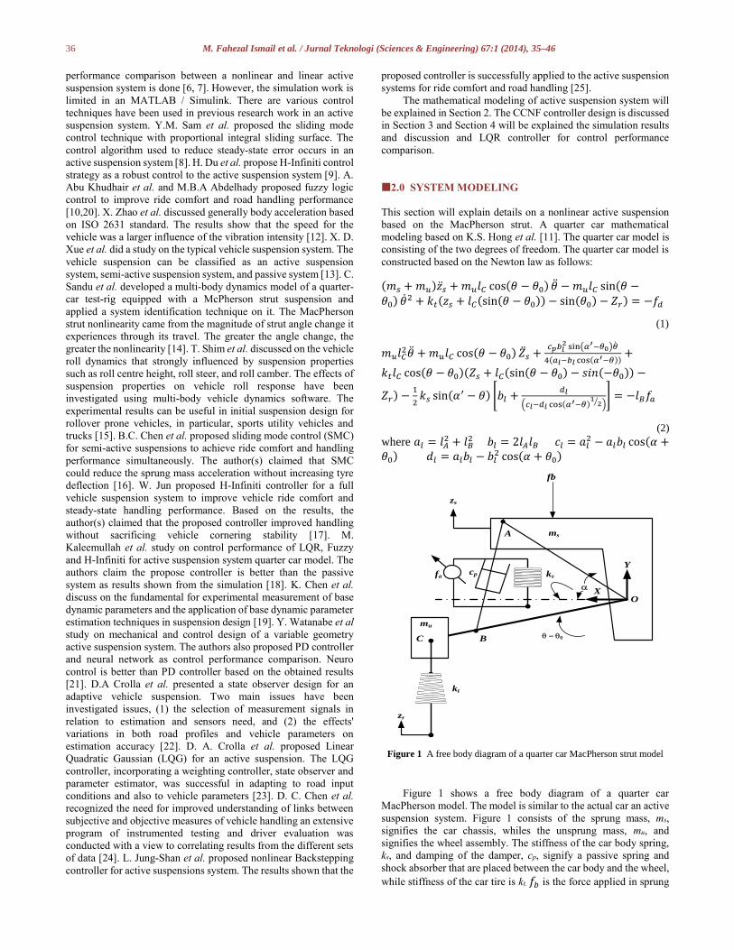
Figure 1 A free body diagram of a quarter car MacPherson strut model
Figure 1 shows a free body diagram of a quarter car
MacPherson model. The model is similar to the actual car an active
suspension system. Figure 1 consists of the sprung mass, ms,
signifies the car chassis, whiles the unsprung mass, mu, and
signifies the wheel assembly. The stiffness of the car body spring,
ks, and damping of the damper, cp, signify a passive spring and
shock absorber that are placed between the car body and the wheel,
while stiffness of the car tire is kt. 𝑓𝑏 is the force applied in sprung
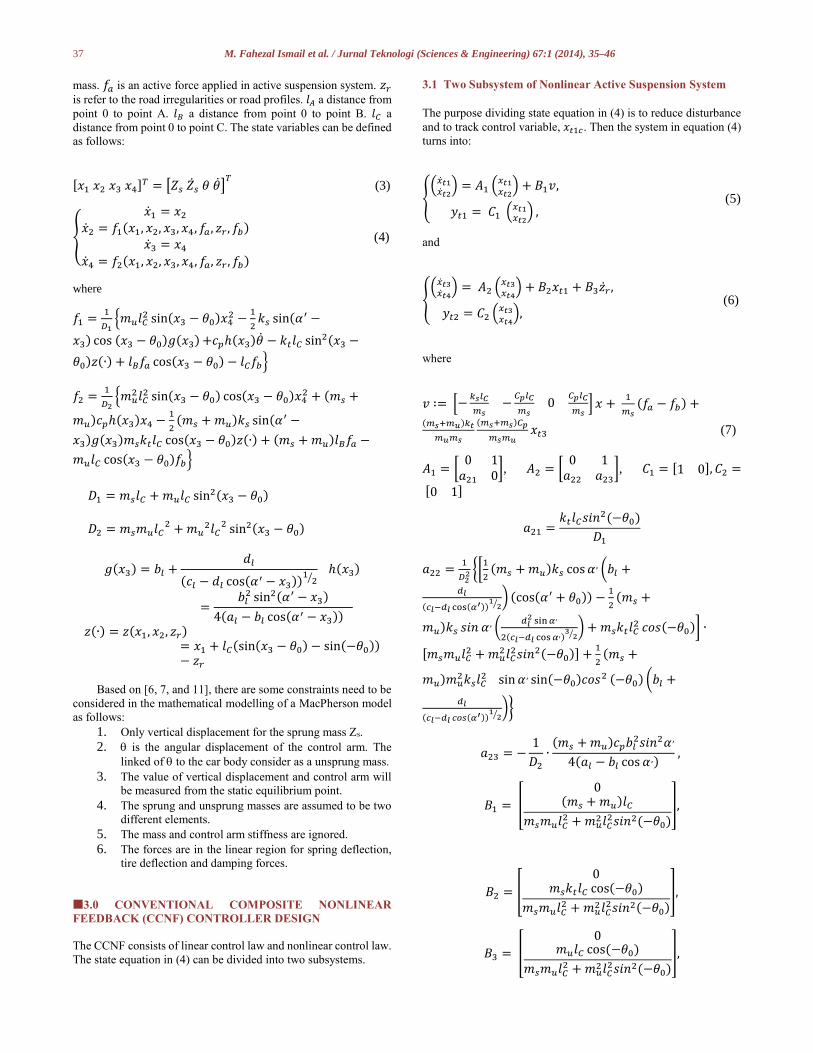
37 M. Fahezal Ismail et al. / Jurnal Teknologi (Sciences & Engineering) 67:1 (2014), 35–46
mass. 𝑓𝑎 is an active force applied in active suspension system. 𝑧𝑟
is refer to the road irregularities or road profiles. 𝑙𝐴 a distance from
point 0 to point A. 𝑙𝐵 a distance from point 0 to point B. 𝑙𝐶 a
distance from point 0 to point C. The state variables can be defined
as follows:
[𝑥1 𝑥2 𝑥3 𝑥4]𝑇 = [𝑍𝑠 �̇�𝑠 𝜃 �̇�]𝑇 (3)
{
�̇�1 = 𝑥2
�̇�2 = 𝑓1(𝑥1, 𝑥2, 𝑥3, 𝑥4, 𝑓𝑎, 𝑧𝑟 , 𝑓𝑏)
�̇�3 = 𝑥4
�̇�4 = 𝑓2(𝑥1, 𝑥2, 𝑥3, 𝑥4, 𝑓𝑎, 𝑧𝑟 , 𝑓𝑏)
(4)
where
𝑓1 =1
𝐷1{𝑚𝑢𝑙𝐶
2 sin(𝑥3 − 𝜃0)𝑥42 −
1
2𝑘𝑠 sin(𝛼′ −
𝑥3) cos (𝑥3 − 𝜃0)𝑔(𝑥3) +𝑐𝑝ℎ(𝑥3)�̇� − 𝑘𝑡𝑙𝐶 sin2(𝑥3 −
𝜃0)𝑧(∙) + 𝑙𝐵𝑓𝑎 cos(𝑥3 − 𝜃0) − 𝑙𝐶𝑓𝑏}
𝑓2 =1
𝐷2{𝑚𝑢
2𝑙𝐶2 sin(𝑥3 − 𝜃0) cos(𝑥3 − 𝜃0)𝑥4
2 + (𝑚𝑠 +
𝑚𝑢)𝑐𝑝ℎ(𝑥3)𝑥4 −1
2(𝑚𝑠 + 𝑚𝑢)𝑘𝑠 sin(𝛼′ −
𝑥3)𝑔(𝑥3)𝑚𝑠𝑘𝑡𝑙𝐶 cos(𝑥3 − 𝜃0)𝑧(∙) + (𝑚𝑠 + 𝑚𝑢)𝑙𝐵𝑓𝑎 −
𝑚𝑢𝑙𝐶 cos(𝑥3 − 𝜃0)𝑓𝑏}
𝐷1 = 𝑚𝑠𝑙𝐶 + 𝑚𝑢𝑙𝐶 sin2(𝑥3 − 𝜃0)
𝐷2 = 𝑚𝑠𝑚𝑢𝑙𝐶2 + 𝑚𝑢
2𝑙𝐶2 sin2(𝑥3 − 𝜃0)
𝑔(𝑥3) = 𝑏𝑙 +𝑑𝑙
(𝑐𝑙 − 𝑑𝑙 cos(𝛼′ − 𝑥3))1
2⁄ ℎ(𝑥3)
=𝑏𝑙
2 sin2(𝛼′ − 𝑥3)
4(𝑎𝑙 − 𝑏𝑙 cos(𝛼′ − 𝑥3))
𝑧(∙) = 𝑧(𝑥1, 𝑥2, 𝑧𝑟)= 𝑥1 + 𝑙𝐶(sin(𝑥3 − 𝜃0) − sin(−𝜃0))− 𝑧𝑟
Based on [6, 7, and 11], there are some constraints need to be
considered in the mathematical modelling of a MacPherson model
as follows:
1. Only vertical displacement for the sprung mass Zs.
2. q is the angular displacement of the control arm. The
linked of q to the car body consider as a unsprung mass.
3. The value of vertical displacement and control arm will
be measured from the static equilibrium point.
4. The sprung and unsprung masses are assumed to be two
different elements.
5. The mass and control arm stiffness are ignored.
6. The forces are in the linear region for spring deflection,
tire deflection and damping forces.
3.0 CONVENTIONAL COMPOSITE NONLINEAR
FEEDBACK (CCNF) CONTROLLER DESIGN
The CCNF consists of linear control law and nonlinear control law.
The state equation in (4) can be divided into two subsystems.
3.1 Two Subsystem of Nonlinear Active Suspension System
The purpose dividing state equation in (4) is to reduce disturbance
and to track control variable, 𝑥𝑡1𝑐 . Then the system in equation (4)
turns into:
{(�̇�𝑡1
�̇�𝑡2) = 𝐴1 (𝑥𝑡1
𝑥𝑡2) + 𝐵1𝑣,
𝑦𝑡1 = 𝐶1 (𝑥𝑡1𝑥𝑡2
) , (5)
and
{(�̇�𝑡3
�̇�𝑡4) = 𝐴2 (𝑥𝑡3
𝑥𝑡4) + 𝐵2𝑥𝑡1 + 𝐵3�̇�𝑟 ,
𝑦𝑡2 = 𝐶2 (𝑥𝑡3𝑥𝑡4
), (6)
where
𝑣 ∶= [−𝑘𝑠𝑙𝐶
𝑚𝑠−
𝐶𝑝𝑙𝐶
𝑚𝑠0
𝐶𝑝𝑙𝐶
𝑚𝑠] 𝑥 +
1
𝑚𝑠(𝑓𝑎 − 𝑓𝑏) +
(𝑚𝑠+𝑚𝑢)𝑘𝑡
𝑚𝑢𝑚𝑠
(𝑚𝑠+𝑚𝑠)𝐶𝑝
𝑚𝑠𝑚𝑢𝑥𝑡3 (7)
𝐴1 = [0 1
𝑎21 0], 𝐴2 = [
0 1𝑎22 𝑎23
], 𝐶1 = [1 0], 𝐶2 =
[0 1]
𝑎21 =𝑘𝑡𝑙𝐶𝑠𝑖𝑛2(−𝜃0)
𝐷1
𝑎22 =1
𝐷22 {[
1
2(𝑚𝑠 + 𝑚𝑢)𝑘𝑠 cos 𝛼 , (𝑏𝑙 +
𝑑𝑙
(𝑐𝑙−𝑑𝑙 cos(𝛼′))1
2⁄) (cos(𝛼′ + 𝜃0)) −
1
2(𝑚𝑠 +
𝑚𝑢)𝑘𝑠 𝑠𝑖𝑛 𝛼 , (𝑑𝑙
2 sin 𝛼,
2(𝑐𝑙−𝑑𝑙 cos 𝛼,)3
2⁄) + 𝑚𝑠𝑘𝑡𝑙𝐶
2 𝑐𝑜𝑠(−𝜃0)] ∙
[𝑚𝑠𝑚𝑢𝑙𝐶2 + 𝑚𝑢
2𝑙𝐶2𝑠𝑖𝑛2(−𝜃0)] +
1
2(𝑚𝑠 +
𝑚𝑢)𝑚𝑢2𝑘𝑠𝑙𝐶
2 sin 𝛼 , sin(−𝜃0)𝑐𝑜𝑠2 (−𝜃0) (𝑏𝑙 +
𝑑𝑙
(𝑐𝑙−𝑑𝑙 𝑐𝑜𝑠(𝛼′))1
2⁄)}
𝑎23 = −1
𝐷2
∙(𝑚𝑠 + 𝑚𝑢)𝑐𝑝𝑏𝑙
2𝑠𝑖𝑛2𝛼 ,
4(𝑎𝑙 − 𝑏𝑙 cos 𝛼 ,) ,
𝐵1 = [
0(𝑚𝑠 + 𝑚𝑢)𝑙𝐶
𝑚𝑠𝑚𝑢𝑙𝐶2 + 𝑚𝑢
2𝑙𝐶2𝑠𝑖𝑛2(−𝜃0)
],
𝐵2 = [
0𝑚𝑠𝑘𝑡𝑙𝐶 cos(−𝜃0)
𝑚𝑠𝑚𝑢𝑙𝐶2 + 𝑚𝑢
2𝑙𝐶2𝑠𝑖𝑛2(−𝜃0)
],
𝐵3 = [
0𝑚𝑢𝑙𝐶 cos(−𝜃0)
𝑚𝑠𝑚𝑢𝑙𝐶2 + 𝑚𝑢
2𝑙𝐶2𝑠𝑖𝑛2(−𝜃0)
],
38 M. Fahezal Ismail et al. / Jurnal Teknologi (Sciences & Engineering) 67:1 (2014), 35–46
3.2 Linear Control Law
Equation (5) is used to design linear part in CCNF as follow to track
the control variable 𝑥𝑡1𝑐.as follow:
𝑣1𝐿 = 𝐹1 (𝑥𝑡1
𝑥𝑡2) + 𝐺1𝑥𝑡1𝑐 (8)
where
𝐹1 = −[4𝜋2𝑓1
2 + 𝑎1 4𝜋𝑓1𝜁1]
(𝑚𝑠 + 𝑚𝑢)𝑙𝐶
𝑚𝑠𝑚𝑢𝑙𝐶2 + 𝑚𝑢
2𝑙𝐶2𝑠𝑖𝑛2(−𝜃0)
with frequency of 𝑓1 = 10 Hz and 𝜁1= 0.32 for quickly tracking. It
can be checked that (𝐴1 + 𝐵1𝐹1) is asymptotically stable.
𝐺1 =1
𝐶1(𝐴1 + 𝐵1𝐹1)−1𝐵1
For equation (6), the linear control law is designed as follows:
𝑣2𝐿 = 𝐹2 (𝑥𝑡3
𝑥𝑡4) (9)
where the item of 𝐺2𝑟 is ignored in the linear control law as the
reference 𝑟 = 0.
𝐹2 = [0𝜁2
𝜋𝑓2]
with frequency of 𝑓2 = 3.5684Hz, the natural frequency of (6), and
𝜁2 = 0.55 to reduce the disturbance with the small control signal.
It can be checked that (𝐴1 + 𝐵1𝐹1) is asymptotically stable.
3.3 Nonlinear Control Law
For equation (5) the nonlinear part can be designed as follows:
𝑣1𝑁 = 𝜌1(𝑦𝑡1)𝑁1 [(𝑥𝑡1
𝑥𝑡2) −𝑥𝑒] (10)
where
𝑁1 = [4𝜋2𝑓1
2 𝜁1 𝜋𝑓1⁄ ]
(𝑚𝑠 + 𝑚𝑢)𝑙𝐶
𝑚𝑠𝑚𝑢𝑙𝐶2 + 𝑚𝑢
2𝑙𝐶2𝑠𝑖𝑛2(−𝜃0)
,
𝜌1 = −4.53𝑒−15.685|𝑦𝑡1| − 𝑒−1
1 − 𝑒−1.
𝜌1 is to be designed. 𝑁1 = 𝐵1
′ 𝑃1 in which 𝑃1 > 0 is a solution of
the Lyapunov equation given by
(𝐴1 + 𝐵1𝐹1)′𝑃1 + 𝑃1(𝐴1 + 𝐵1𝐹1) = −𝑊1,
𝑊1 = 𝑑𝑖𝑎𝑔 [
40𝜋4𝑓14
(𝑚𝑠 + 𝑚𝑢)𝑙𝐶
𝑚𝑠𝑚𝑢𝑙𝐶2 + 𝑚𝑢
2𝑙𝐶2𝑠𝑖𝑛2(−𝜃0)
10−6
]
As 𝑥𝑡1𝑐 is a non-step reference, 𝑥𝑒 is generated by a signal
generator as follows
�̇�𝑒 = 𝐴𝑒𝑥𝑒 + 𝐵𝑒𝑥𝑡1𝑐, 𝐴𝑒 = 𝐴1 + 𝐵1𝐹1
𝐵𝑒 = 𝐵1𝐺1 (11)
For equation (6) the nonlinear feedback part as follows:
𝑣2𝑁 = 𝜌2(𝑦𝑡2)𝑁2 (𝑥𝑡3
𝑥𝑡4) (12)
where 𝑥𝑒2 = 0 as the reference 𝑟 = 0.
𝑁2 = [0𝜁2
𝜋𝑓2], 𝜌2 = −1.4877
𝑒−2.544|𝑦𝑡2| − 𝑒−1
1 − 𝑒−1.
𝜌2 is designed to remove the overshoot and 𝑁2 = 𝐵2′ 𝑃2 in which
𝑃2 > 0 is a solution of the Lyapunov equation given by
(𝐴2 + 𝐵2𝐹2)′𝑃2 + 𝑃2(𝐴2 + 𝐵2𝐹2) = −𝑊2, 𝑊2 =
𝑑𝑖𝑎𝑔 [10−6 2𝜁22
𝜋2𝑓22].
The complete CNF control law for equation (5) as follows,
𝑣 = 𝑣1𝐿 + 𝑣1𝑁 = 𝐹1 (𝑥𝑡1
𝑥𝑡2) + 𝐺1𝑥𝑡1𝑐 +
𝜌1(𝑦𝑡1)𝑁1 [(𝑥𝑡1
𝑥𝑡2) −𝑥𝑒] (13)
and for equation (6) as follows,
𝑥𝑡1𝑐 = 𝑣2𝐿 + 𝑣2𝑁 = (𝐹2 + 𝜌2(𝑦𝑡2)𝑁2) (𝑥𝑡3
𝑥𝑡4) (14)
4.0 RESULTS AND DISCUSSION
The numerical experiment is performed using the CarSim. Figure
2 shows the Simulink block used to design the control algorithm of
CCNF and its integration with CarSim. All selected parameters are
imported from CarSim and feed into Simulink to for CCNF
controller design. In order to do a control performance for this
numerical experimental, the LQR controller is defining as:
𝑢(𝑡) = −𝐾𝑥(𝑡), (15)
where K is state feedback gain matrix.
The complete LQR equation as follows:
𝐽𝐿𝑄𝑅 =1
2∫ (𝑥𝑇𝑄𝑥 + 𝑢𝑇𝑅𝑢)𝑑𝑡
∞
0, (16)

39 M. Fahezal Ismail et al. / Jurnal Teknologi (Sciences & Engineering) 67:1 (2014), 35–46
The matrix gain K is represented
𝐾 = 𝑅−1𝐵′𝑃, (17)
The matrix P must satisfy the reduced-matrix Riccati equation.
𝐴′𝑃 + 𝑃𝐴 − 𝑃𝐵𝑅′𝐵′𝑃 + 𝑄 = 0 (18)
Then the feedback regulator
𝑈 = −(𝑅−1𝐵′𝑃)𝑥 (19)
In this research study, vertical acceleration is considered as a
ride quality index. The criterion recommended by the International
Standard Organization (ISO2631, 1985, 1989) provides the
frequency weighting curve relating to vertical acceleration. The
vertical weighting function is given in ISO2631. The weighted
RMS vertical acceleration can be computed from the equation,
𝑎𝑅𝑀𝑆 = [1
𝑇∫ 𝑎𝑤
2 (𝑡)𝑑𝑡𝑇
0]
1
2 (4.2)
where 𝑎𝑤 (𝑡) is the weighted vertical acceleration of a driver’s
seat. The vertical weighting function is given in ISO2631. Table 1
shows the relationship between the vertical acceleration level and
the degree of comfort. Table 2 is shown as a parameter used in the
simulation for CNF controller and passive system.
Table 1 RMS vertical acceleration level and degree of comfort (ISO2631-
1, 1997)
RMS vertical acceleration level Degree of comfort
(1) Less than 0.315 m/s2 Not uncomfortable
(2) 0.315-0.63 m/s2 A little uncomfortable
(3) 0.5-1 m/s2 Fairly uncomfortable
(4) 0.8-1.6 m/s2 Uncomfortable
(5) 1.25-2.5 m/s2 Very uncomfortable
(6) Greater than 2 m/s2 Extremely uncomfortable
Table 2 Physical parameters for quarter car model
Parameter Value
Mass of a car body 455 kg
Mass of a car wheel 71 kg
Stiffness of a car body spring 17,659 N/m
Stiffness of a car tire 183,888 N/m
Damper coefficient 1950 Ns/m
Distance from point 0 to A 0.37 m
Distance from point 0 to B 0.64 m
Distance from point 0 to C 0.66 m
Before running the numerical experimental and numerical
simualtion in both environments in MATLAB/Simulink and
CarSim, the initial setting must be done first in CarSim. Figure 3
shows the independent suspension kinematic screen for active
suspension system setting. The physical parameters involved as
shown in Table 2 is used. The kinematics of the suspension
linkages is described by the lateral and longitudinal motions of the
wheel as the suspension deflects vertically. The lateral movement
primarily affects the transfer of tire lateral force of the body and the
resulting body roll. The longitudinal movement primarily affects
the transfer of tire longitudinal force of the body and the resulting
body pitch. The motion of the wheels is defined by the positions of
the wheel centre, and by camber and caster changes as each wheel
moves in jounce.
Figure 2 MATLAB/Simulink block diagram integrated with CarSim in CCNF
40 M. Fahezal Ismail et al. / Jurnal Teknologi (Sciences & Engineering) 67:1 (2014), 35–46
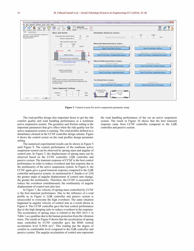
Figure 3 Control screen for active suspension parameter setup
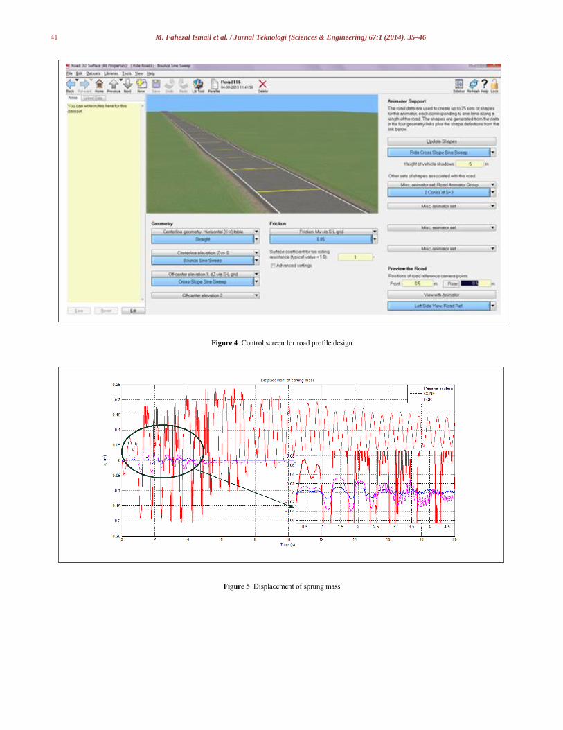
The road profiles design also important factor to get the ride
comfort quality and road handling performance in a nonlinear
active suspension system. The geometry and friction setting is the
important parameters that give effect when the ride quality test for
active suspension system is running. The road profiles defined as a
disturbance element in the CCNF controller design scheme. Figure
4 shows the control screen on the road profiles design parameter
setting
The numerical experimental results can be shown in Figure 5
until Figure 9. The control performance of the nonlinear active
suspension system can be observed by sprung mass and angular of
control arm. In Figure 5, the displacement of sprung mass can be
observed based on the CCNF controller, LQR controller and
passive system. The transient response of CCNF is the best control
performance in order to reduce overshoot and fast response due to
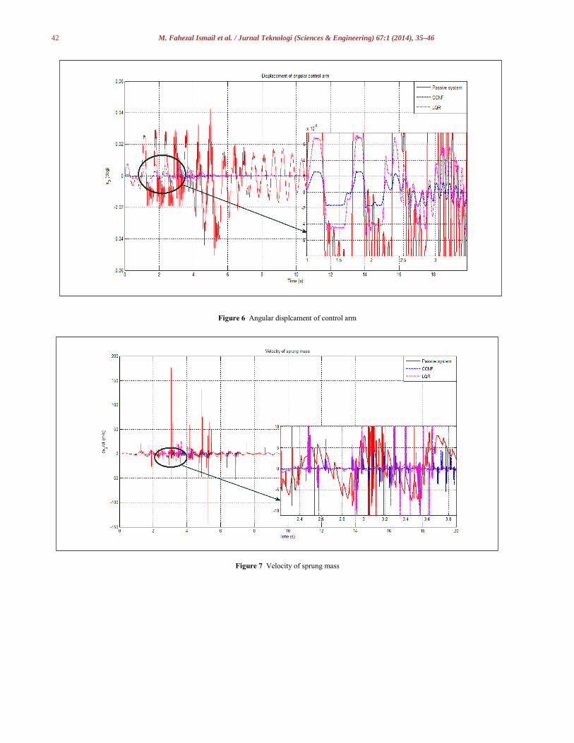
the nonlinearity of the active suspension system. In Figure 6, the
CCNF again gave a good transient response compared to the LQR
controller and passive system. As mentioned by C.Sandu et al. [14]
the greater angle of angular displacement of control arm change,
the greater the nonlinearity. Therefore, the CCNF is succeeded to
reduce the overshoot simultaneously the nonlinearity of angular
displacement of control arm also less.
In Figure 7, the velocity of sprung mass controlled by CCNF
is the best transient performance. Due to the influence of a road
profile as in Figure 4, LQR controller and passive system is
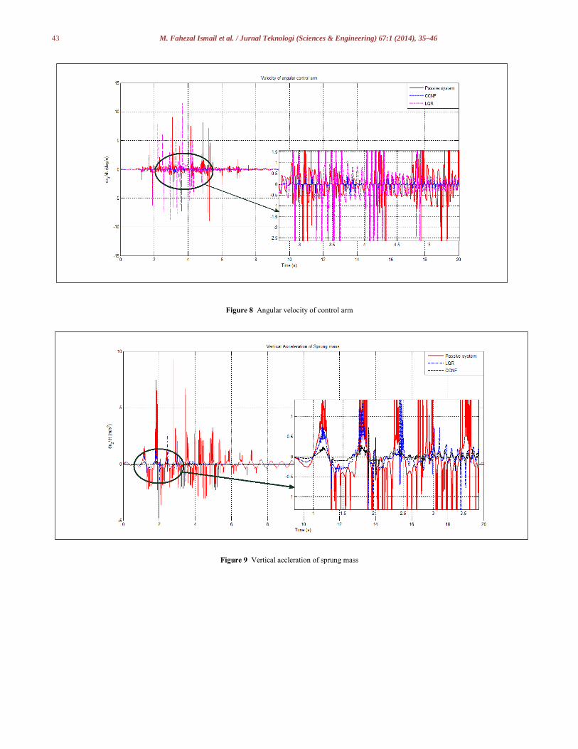
unsuccesful to overcome the high overshoot. The same situation
happened in angular velocity of control arm as a result shown in
Figure 8. The CCNF controller gave the best control performance
due to the high damping ratio to reduce overshoot in the response.
The acceleration of sprung mass is refered to the ISO 2631-1 in
Table 1 as a guidline due to the human protection from the vibration
noise. The results in Figure 9 shown that the acceleration of sprung
mass controlled by CCNF controller gave the RMS vertical
accelaration level 0.2856 m/s2. This reading put the degree of
comfort in comfortable level compared to the LQR controller and
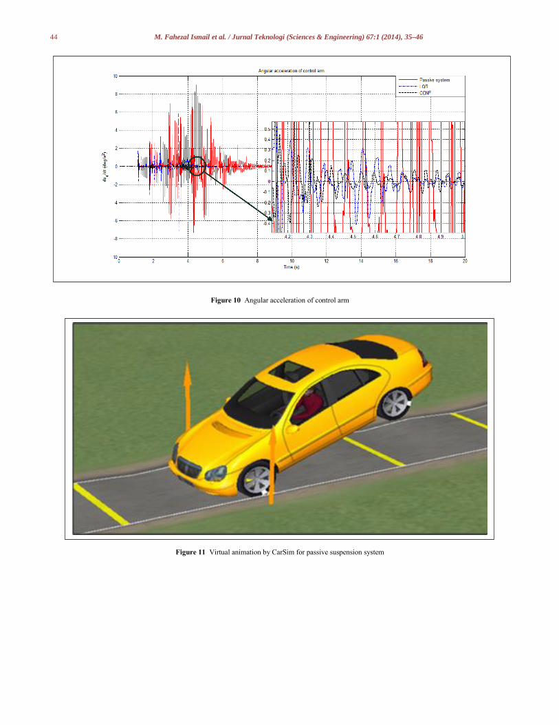
passive system. The angular accelaration of control arm represents
the road handling performance of the car an active suspension
system. The result in Figure 10 shows that the best transient
response came from CCNF controller compared to the LQR
controller and passive system.
41 M. Fahezal Ismail et al. / Jurnal Teknologi (Sciences & Engineering) 67:1 (2014), 35–46
Figure 4 Control screen for road profile design
Figure 5 Displacement of sprung mass
42 M. Fahezal Ismail et al. / Jurnal Teknologi (Sciences & Engineering) 67:1 (2014), 35–46
Figure 6 Angular displcament of control arm
Figure 7 Velocity of sprung mass
43 M. Fahezal Ismail et al. / Jurnal Teknologi (Sciences & Engineering) 67:1 (2014), 35–46
Figure 8:
Figure 8 Angular velocity of control arm
Figure 9 Vertical accleration of sprung mass
44 M. Fahezal Ismail et al. / Jurnal Teknologi (Sciences & Engineering) 67:1 (2014), 35–46
Figure 10 Angular acceleration of control arm
Figure 11 Virtual animation by CarSim for passive suspension system
45 M. Fahezal Ismail et al. / Jurnal Teknologi (Sciences & Engineering) 67:1 (2014), 35–46
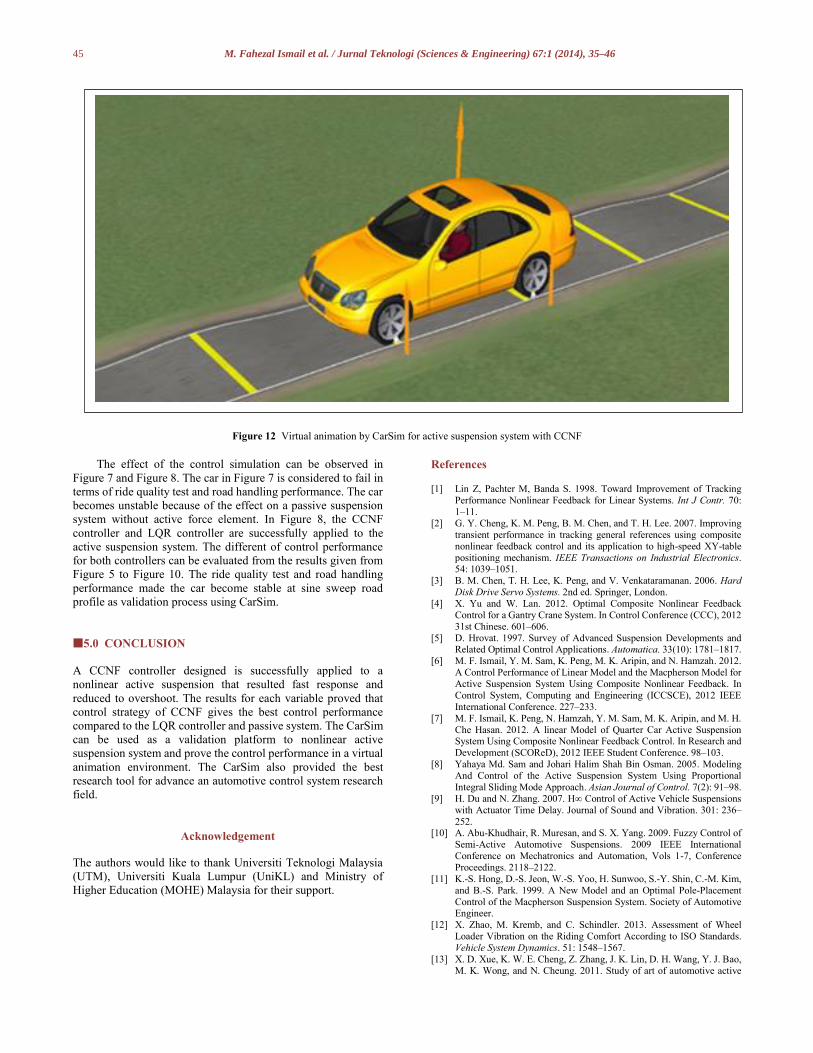
Figure 12 Virtual animation by CarSim for active suspension system with CCNF
The effect of the control simulation can be observed in
Figure 7 and Figure 8. The car in Figure 7 is considered to fail in
terms of ride quality test and road handling performance. The car
becomes unstable because of the effect on a passive suspension
system without active force element. In Figure 8, the CCNF
controller and LQR controller are successfully applied to the
active suspension system. The different of control performance
for both controllers can be evaluated from the results given from
Figure 5 to Figure 10. The ride quality test and road handling
performance made the car become stable at sine sweep road
profile as validation process using CarSim.
5.0 CONCLUSION
A CCNF controller designed is successfully applied to a
nonlinear active suspension that resulted fast response and
reduced to overshoot. The results for each variable proved that
control strategy of CCNF gives the best control performance
compared to the LQR controller and passive system. The CarSim
can be used as a validation platform to nonlinear active
suspension system and prove the control performance in a virtual
animation environment. The CarSim also provided the best
research tool for advance an automotive control system research
field.
Acknowledgement
The authors would like to thank Universiti Teknologi Malaysia
(UTM), Universiti Kuala Lumpur (UniKL) and Ministry of
Higher Education (MOHE) Malaysia for their support.
References [1] Lin Z, Pachter M, Banda S. 1998. Toward Improvement of Tracking
Performance Nonlinear Feedback for Linear Systems. Int J Contr. 70:
1–11.
[2] G. Y. Cheng, K. M. Peng, B. M. Chen, and T. H. Lee. 2007. Improving
transient performance in tracking general references using composite
nonlinear feedback control and its application to high-speed XY-table
positioning mechanism. IEEE Transactions on Industrial Electronics. 54: 1039–1051.
[3] B. M. Chen, T. H. Lee, K. Peng, and V. Venkataramanan. 2006. Hard
Disk Drive Servo Systems. 2nd ed. Springer, London.
[4] X. Yu and W. Lan. 2012. Optimal Composite Nonlinear Feedback
Control for a Gantry Crane System. In Control Conference (CCC), 2012
31st Chinese. 601–606.
[5] D. Hrovat. 1997. Survey of Advanced Suspension Developments and Related Optimal Control Applications. Automatica. 33(10): 1781–1817.
[6] M. F. Ismail, Y. M. Sam, K. Peng, M. K. Aripin, and N. Hamzah. 2012.
A Control Performance of Linear Model and the Macpherson Model for
Active Suspension System Using Composite Nonlinear Feedback. In
Control System, Computing and Engineering (ICCSCE), 2012 IEEE
International Conference. 227–233.
[7] M. F. Ismail, K. Peng, N. Hamzah, Y. M. Sam, M. K. Aripin, and M. H.
Che Hasan. 2012. A linear Model of Quarter Car Active Suspension System Using Composite Nonlinear Feedback Control. In Research and
Development (SCOReD), 2012 IEEE Student Conference. 98–103.
[8] Yahaya Md. Sam and Johari Halim Shah Bin Osman. 2005. Modeling
And Control of the Active Suspension System Using Proportional
Integral Sliding Mode Approach. Asian Journal of Control. 7(2): 91–98.
[9] H. Du and N. Zhang. 2007. H∞ Control of Active Vehicle Suspensions
with Actuator Time Delay. Journal of Sound and Vibration. 301: 236–
252. [10] A. Abu-Khudhair, R. Muresan, and S. X. Yang. 2009. Fuzzy Control of
Semi-Active Automotive Suspensions. 2009 IEEE International
Conference on Mechatronics and Automation, Vols 1-7, Conference
Proceedings. 2118–2122.
[11] K.-S. Hong, D.-S. Jeon, W.-S. Yoo, H. Sunwoo, S.-Y. Shin, C.-M. Kim,
and B.-S. Park. 1999. A New Model and an Optimal Pole-Placement
Control of the Macpherson Suspension System. Society of Automotive Engineer.
[12] X. Zhao, M. Kremb, and C. Schindler. 2013. Assessment of Wheel
Loader Vibration on the Riding Comfort According to ISO Standards.
Vehicle System Dynamics. 51: 1548–1567.
[13] X. D. Xue, K. W. E. Cheng, Z. Zhang, J. K. Lin, D. H. Wang, Y. J. Bao,
M. K. Wong, and N. Cheung. 2011. Study of art of automotive active
46 M. Fahezal Ismail et al. / Jurnal Teknologi (Sciences & Engineering) 67:1 (2014), 35–46
suspensions. In Power Electronics Systems and Applications (PESA),
2011 4th International Conference on. 1–7.
[14] C. Sandu, E. R. Andersen, and S. Southward. 2010. Multibody
Dynamics Modelling and System Identification of a Quarter-car Test
Rig with McPherson Strut Suspension. Vehicle System Dynamics. 49: 153–179.
[15] T. Shim and P. C. Velusamy. 2010. Improvement of Vehicle Roll
Stability by Varying Suspension Properties. Vehicle System Dynamics.
49: 129–152.
[16] B.-C. Chen, Y.-H. Shiu, and F.-C. Hsieh. 2010. Sliding-mode Control
for Semi-active Suspension with Actuator Dynamics. Vehicle System
Dynamics. 49: 277–290. [17] W. Jun, D. A. Wilson, X. Wenli, and D. A. Crolla. 2005. Active
Suspension Control to Improve Vehicle Ride and Steady-State
Handling. In Decision and Control, 2005 and 2005 European Control
Conference. CDC-ECC '05. 44th IEEE Conference on. 1982–1987.
[18] M. Kaleemullah, W. F. Faris, and F. Hasbullah. 2011. Design of Robust
H-Infiniti, Fuzzy and LQR Controller for Active Suspension of a Quarter
Car Model. In Mechatronics (ICOM), 2011 4th International Conference
On. 1–6.
[19] K. Chen and D. G. Beale. 2003. Base Dynamic Parameter Estimation of
a MacPherson Suspension Mechanism. Vehicle System Dynamics. 39:
227–244.
[20] M. B. A. Abdelhady. 2003. A Fuzzy Controller for Automotive Active
Suspension Systems. [21] Y. Watanabe and R. S. Sharp. 1999. Mechanical and Control Design of
a Variable Geometry Active Suspension System. Vehicle System
Dynamics. 32: 217–235.
[22] F. Yu and D. A. Crolla. 1998. State Observer Design for an Adaptive
Vehicle Suspension. Vehicle System Dynamics. 30: 457–471.
[23] F. Yu and D. A. Crolla. 1998. An Optimal Self-Tuning Controller for an
Active Suspension. Vehicle System Dynamics. 29: 51–65. [24] D. C. Chen and D. A. Crolla. 1998. Subjective And Objective Measures
Of Vehicle Handling: Drivers & Experiments. Vehicle System
Dynamics. 29: 576–597.
[25] L. Jung-Shan and I. Kanellakopoulos. 1997. Nonlinear Design of Active
Suspensions. Control Systems, IEEE. 17: 45–59.