20-21 September 2010 Rollover Prevention System for ...
8
iDECON 2010 – International Conference on Design and Concurrent Engineering Universiti Teknikal Malaysia Melaka (UTeM) 20-21 September 2010 287 Rollover Prevention System for Passenger Vehicle Mochamad Safarudin 1* , Amrik Singh 1 , and Haeryip Sihombing 2 1 Faculty of Mechanical Engineering, University Teknikal Malaysia Melaka, Durian Tunggal, 76109 Melaka, Malaysia 2 Faculty of Manufacturing Engineering, University Teknikal Malaysia Melaka, Durian Tunggal, 76109 Melaka, Malaysia *corresponding author: [email protected] Abstract – An active roll control using roll moment rejection algorithm based on 14 DOF full vehicle model is proposed in this paper. For tire model, the Magic Tire formula was used. The full vehicle model was simulated and compared with vehicle dynamics simulation software and validated using an instrumented experimental vehicle. The active roll control algorithm was then introduced to the vehicle model. Combined with PID control, the results were then simulated and analyzed. From the simulation, it was found that the algorithm can significantly reduce the roll angle and roll rate of the vehicle and eventually prevent the vehicle from rollover. The improvement of the roll motion also reduces the load transfer from the inner wheels to outer wheels and hence increases the road holding during cornering. Keywords – Active roll control, PID control, Magic Formula, 14 DOF full vehicle model I. INTRODUCTION Various types of electronic control systems have been actively employed in automotive applications to improve vehicle handling and passenger safety [5]. Active suspension was introduced to provide solution between conflict requirement between ride and handling. Although active suspension research have been carried out for years, most of the studies focuses on the ride comfort and very few of the researchers concentrated on the improvement of the vehicle handling using active suspension. Active roll control is an example of active suspension used to improve vehicle handling and passenger safety. During cornering, the roll moment causes the normal load transfer from inner wheels to outer wheels. This load transfer strongly influences the lateral vehicle dynamics. Due to non-linear properties of pneumatics tires, the total lateral force capability of front or rear axle decreases as a result of load transfer. To overcome this problem, an active roll control system is introduced to reduce load transfer during cornering. Active roll control system enables the modulation the normal force at each corner of the vehicle body and hence it is capable of reducing vehicle body roll motion. The objective of this paper is to investigate the performance of active roll control system in reducing vehicle body roll motion and hence preventing vehicle rollover. II. VEHICLE MODELING Shim [8] presented a comprehensive 14 DOF vehicle model which includes the dynamics of the roll center to study the roll behavior of the vehicle. The tire model used was the Magic Formula tire model. Step steer, ramp steer, and J-turn inputs were given to the vehicle model for validation purpose. The limitation, simplified equation validity and assumption of various modeling was discussed by analyzing their effect on the model roll response for step steer, ramp steer and J turn test. This paper presented development of 14 DOF vehicle model and implementation of active roll control structure on the validated vehicle model. This 14-DOF vehicle model was used by researchers in references [3], [6], and [8] in predicting the dynamic behavior of the vehicle. A. Vehicle Model The 14 DOF vehicle model shown in Fig. 1 is sufficient to study the dynamic behavior of the vehicle in longitudinal, lateral, and vertical direction. This model is made up of a sprung mass and four unsprung masses. The vehicle body has 6 DOF which are translational motions in x, y, and z direction and angular motions about those three axes. Roll, pitch and yaw motions are the rotation about x, y, and z axes respectively. Each of the wheels has translational motion in z direction and wheel spin about y direction. Magic Formula tire model [4] is used to represent the longitudinal and lateral tire behavior. Fig. 1. 14 DOF Full Vehicle Model brought to you by CORE View metadata, citation and similar papers at core.ac.uk provided by Universiti Teknikal Malaysia Melaka (UTeM) Repository
Transcript of 20-21 September 2010 Rollover Prevention System for ...
iDECON 2010 – International Conference on Design and Concurrent Engineering
Universiti Teknikal Malaysia Melaka (UTeM) 20-21 September 2010
287
Rollover Prevention System for Passenger Vehicle
Mochamad Safarudin
1*, Amrik Singh
1, and Haeryip Sihombing2
1Faculty of Mechanical Engineering,
University Teknikal Malaysia Melaka, Durian Tunggal, 76109 Melaka, Malaysia 2Faculty of Manufacturing Engineering,
University Teknikal Malaysia Melaka, Durian Tunggal, 76109 Melaka, Malaysia
*corresponding author: [email protected]
Abstract – An active roll control using roll moment rejection
algorithm based on 14 DOF full vehicle model is proposed
in this paper. For tire model, the Magic Tire formula was
used. The full vehicle model was simulated and compared
with vehicle dynamics simulation software and validated
using an instrumented experimental vehicle. The active roll
control algorithm was then introduced to the vehicle model.
Combined with PID control, the results were then simulated
and analyzed. From the simulation, it was found that the
algorithm can significantly reduce the roll angle and roll
rate of the vehicle and eventually prevent the vehicle from
rollover. The improvement of the roll motion also reduces
the load transfer from the inner wheels to outer wheels and
hence increases the road holding during cornering.
Keywords – Active roll control, PID control, Magic
Formula, 14 DOF full vehicle model
I. INTRODUCTION
Various types of electronic control systems have
been actively employed in automotive applications to
improve vehicle handling and passenger safety [5].
Active suspension was introduced to provide solution
between conflict requirement between ride and
handling. Although active suspension research have
been carried out for years, most of the studies focuses
on the ride comfort and very few of the researchers
concentrated on the improvement of the vehicle
handling using active suspension. Active roll control is
an example of active suspension used to improve
vehicle handling and passenger safety.
During cornering, the roll moment causes the normal
load transfer from inner wheels to outer wheels. This
load transfer strongly influences the lateral vehicle
dynamics. Due to non-linear properties of pneumatics
tires, the total lateral force capability of front or rear
axle decreases as a result of load transfer. To overcome
this problem, an active roll control system is introduced
to reduce load transfer during cornering. Active roll
control system enables the modulation the normal force
at each corner of the vehicle body and hence it is
capable of reducing vehicle body roll motion.
The objective of this paper is to investigate the
performance of active roll control system in reducing
vehicle body roll motion and hence preventing vehicle
rollover.
II. VEHICLE MODELING
Shim [8] presented a comprehensive 14 DOF vehicle
model which includes the dynamics of the roll center to
study the roll behavior of the vehicle. The tire model
used was the Magic Formula tire model. Step steer,
ramp steer, and J-turn inputs were given to the vehicle
model for validation purpose. The limitation, simplified
equation validity and assumption of various modeling
was discussed by analyzing their effect on the model
roll response for step steer, ramp steer and J turn test.
This paper presented development of 14 DOF vehicle
model and implementation of active roll control
structure on the validated vehicle model. This 14-DOF
vehicle model was used by researchers in references
[3], [6], and [8] in predicting the dynamic behavior of
the vehicle.
A. Vehicle Model
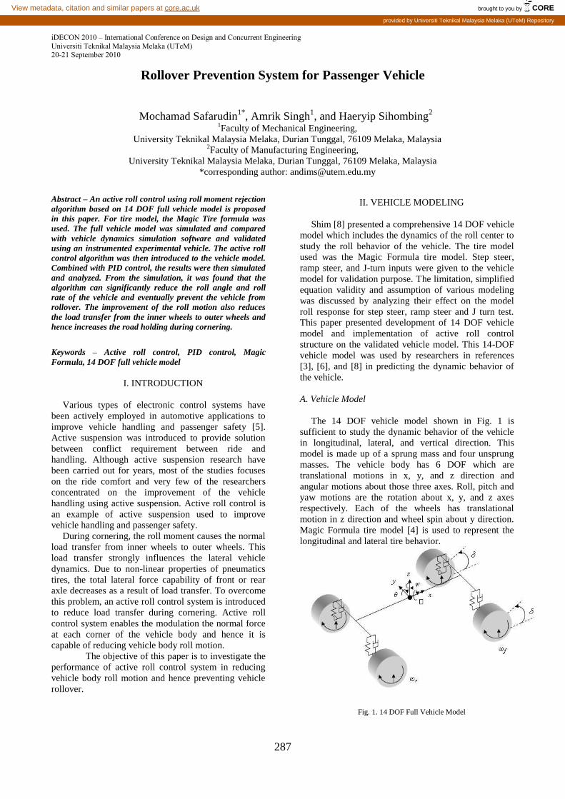
The 14 DOF vehicle model shown in Fig. 1 is
sufficient to study the dynamic behavior of the vehicle
in longitudinal, lateral, and vertical direction. This
model is made up of a sprung mass and four unsprung
masses. The vehicle body has 6 DOF which are
translational motions in x, y, and z direction and
angular motions about those three axes. Roll, pitch and
yaw motions are the rotation about x, y, and z axes
respectively. Each of the wheels has translational
motion in z direction and wheel spin about y direction.
Magic Formula tire model [4] is used to represent the
longitudinal and lateral tire behavior.
Fig. 1. 14 DOF Full Vehicle Model
brought to you by COREView metadata, citation and similar papers at core.ac.uk
provided by Universiti Teknikal Malaysia Melaka (UTeM) Repository
iDECON 2010 – International Conference on Design and Concurrent Engineering
Universiti Teknikal Malaysia Melaka (UTeM) 20-21 September 2010
288
B. Modeling Assumptions
The sprung and unsprung is represented using
lumped mass [3]. The vehicle body is being modeled as
rigid. The outer and inner wheel steer angle is assumed
to be the same. The tires are assumed to having contact
with the ground all the time. Aerodynamics effects are
neglected. Roll center movement was not taken into
account.
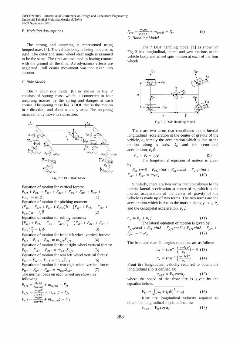
C. Ride Model
The 7 DOF ride model [6] as shown in Fig. 2
consists of sprung mass which is connected to four
unsprung masses by the spring and damper at each
corner. The sprung mass has 3 DOF that is the motion
in z direction, and about x and y axes. The unsprung
mass can only move in z direction.
Fig. 2. 7 DOF Ride Model
Equation of motion for vertical forces:
(1)
Equation of motion for pitching moment:
(2)
Equation of motion for rolling moment:
(3)
Equation of motion for front left wheel vertical forces:
(4)
Equation of motion for front right wheel vertical forces:
(5)
Equation of motion for rear left wheel vertical forces:
(6)
Equation of motion for rear right wheel vertical forces:
(7)
The normal loads on each wheel are shown as
following:
(8)
D. Handling Model
The 7 DOF handling model [1] as shown in
Fig. 3 has longitudinal, lateral and yaw motions at the
vehicle body and wheel spin motion at each of the four
wheels.
Fig. 3. 7 DOF Handling Model
There are two terms that contributes to the inertial
longitudinal acceleration at the center of gravity of the
vehicle, ax namely the acceleration which is due to the
motion along x axis, and the centripetal
acceleration, .
(9)
The longitudinal equation of motion is given
by:
(10)
Similarly, there are two terms that contributes to the
inertial lateral acceleration at center of ay, which is the
inertial acceleration at the center of gravity of the
vehicle is made up of two terms. The two terms are the
acceleration which is due to the motion along y axis,
and the centripetal acceleration, .
(11)
The lateral equation of motion is given by:
(12)
The front and rear slip angles equations are as follow:
(13)
(14)
Front tire longitudinal velocity required to obtain the
longitudinal slip is defined as:
(15)
where the speed of the front tire is given by the
equation below.
(16)
Rear tire longitudinal velocity required to
obtain the longitudinal slip is defined as:
(17)
iDECON 2010 – International Conference on Design and Concurrent Engineering
Universiti Teknikal Malaysia Melaka (UTeM) 20-21 September 2010
289
Y
4
X
3
roll angle
2
yaw rate
1
degree conversion
alpha(degree) alpha(rad)
Subsys ride
ax
ay
phi
Fzfl
Fzfr
Fzrl
Fzrr
Subsys Tire
Fzfl
Fzfr
Fzrl
Fzrr
Sfl
alphafl
Sfr
alphafr
Srl
alpharl
Srr
alpharr
Fxfl
Fyfl
Fxfr
Fyfr
Fxrl
Fyrl
Fxrr
Fyrr
Mzfl
Mzfr
Mzrl
Mzrr
Subsys Handling
delta
Fxfl
Fyfl
Fxfr
Fyfr
Fxrl
Fyrl
Fxrr
Fyrr
Mzfl
Mzfr
Mzrl
Mzrr
Ta
Tb
Vx
X
Y
psi dot
ax
ay
Safl
alpha fl
Safr
alpha fr
Sarl
alpha rl
Sarr
alpha rr
1/gear ratio
1/21
Vx
4
Tb
3
Ta
2
steer
1
Fx
Tb Td
Rw
where the speed of the rear tire is given by the
following equation.
(18)
The front and rears wheel longitudinal slip
under braking condition is defined as follow:
(19)
(20)
The summation of yawing moment is given
by:
(21)
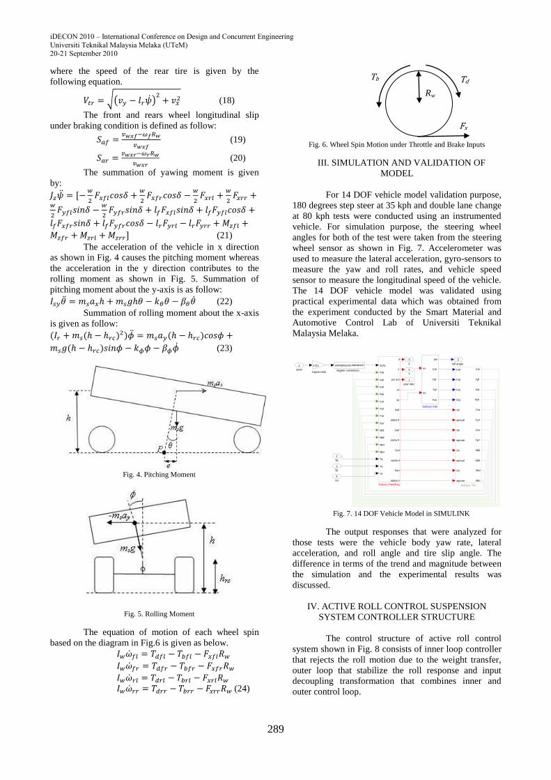
The acceleration of the vehicle in x direction
as shown in Fig. 4 causes the pitching moment whereas
the acceleration in the y direction contributes to the
rolling moment as shown in Fig. 5. Summation of
pitching moment about the y-axis is as follow:
(22)
Summation of rolling moment about the x-axis
is given as follow:
(23)
Fig. 4. Pitching Moment
Fig. 5. Rolling Moment
The equation of motion of each wheel spin
based on the diagram in Fig.6 is given as below.
(24)
Fig. 6. Wheel Spin Motion under Throttle and Brake Inputs
III. SIMULATION AND VALIDATION OF
MODEL
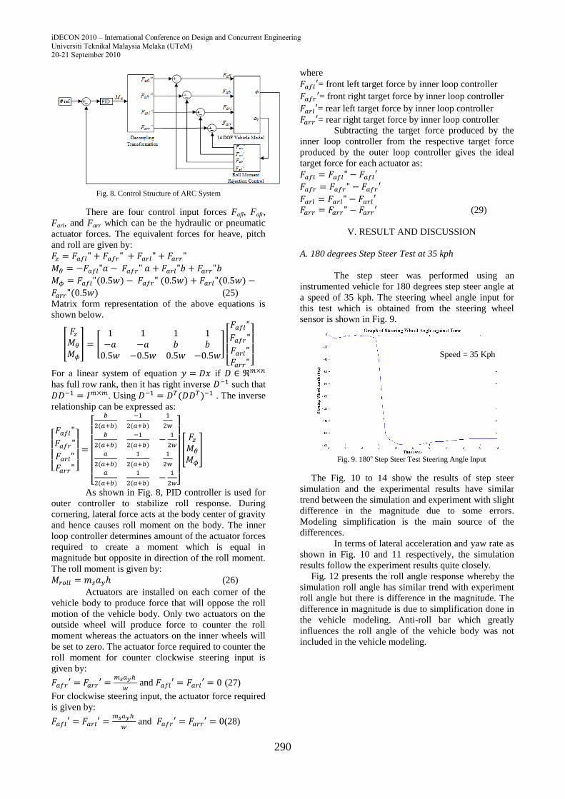
For 14 DOF vehicle model validation purpose,
180 degrees step steer at 35 kph and double lane change
at 80 kph tests were conducted using an instrumented
vehicle. For simulation purpose, the steering wheel
angles for both of the test were taken from the steering
wheel sensor as shown in Fig. 7. Accelerometer was
used to measure the lateral acceleration, gyro-sensors to
measure the yaw and roll rates, and vehicle speed
sensor to measure the longitudinal speed of the vehicle.
The 14 DOF vehicle model was validated using
practical experimental data which was obtained from
the experiment conducted by the Smart Material and
Automotive Control Lab of Universiti Teknikal
Malaysia Melaka.
Fig. 7. 14 DOF Vehicle Model in SIMULINK
The output responses that were analyzed for
those tests were the vehicle body yaw rate, lateral
acceleration, and roll angle and tire slip angle. The
difference in terms of the trend and magnitude between
the simulation and the experimental results was
discussed.
IV. ACTIVE ROLL CONTROL SUSPENSION
SYSTEM CONTROLLER STRUCTURE
The control structure of active roll control
system shown in Fig. 8 consists of inner loop controller
that rejects the roll motion due to the weight transfer,
outer loop that stabilize the roll response and input
decoupling transformation that combines inner and
outer control loop.
iDECON 2010 – International Conference on Design and Concurrent Engineering
Universiti Teknikal Malaysia Melaka (UTeM) 20-21 September 2010
290
Fig. 8. Control Structure of ARC System
There are four control input forces Fafl, Fafr,
Farl, and Farr which can be the hydraulic or pneumatic
actuator forces. The equivalent forces for heave, pitch
and roll are given by:
(25)
Matrix form representation of the above equations is
shown below.
For a linear system of equation if
has full row rank, then it has right inverse such that
. Using . The inverse
relationship can be expressed as:
As shown in Fig. 8, PID controller is used for
outer controller to stabilize roll response. During
cornering, lateral force acts at the body center of gravity
and hence causes roll moment on the body. The inner
loop controller determines amount of the actuator forces
required to create a moment which is equal in
magnitude but opposite in direction of the roll moment.
The roll moment is given by:
(26)
Actuators are installed on each corner of the
vehicle body to produce force that will oppose the roll
motion of the vehicle body. Only two actuators on the
outside wheel will produce force to counter the roll
moment whereas the actuators on the inner wheels will
be set to zero. The actuator force required to counter the
roll moment for counter clockwise steering input is
given by:
and (27)
For clockwise steering input, the actuator force required
is given by:
and (28)
where
= front left target force by inner loop controller
= front right target force by inner loop controller
= rear left target force by inner loop controller
= rear right target force by inner loop controller
Subtracting the target force produced by the
inner loop controller from the respective target force
produced by the outer loop controller gives the ideal
target force for each actuator as:
(29)
V. RESULT AND DISCUSSION
A. 180 degrees Step Steer Test at 35 kph
The step steer was performed using an
instrumented vehicle for 180 degrees step steer angle at
a speed of 35 kph. The steering wheel angle input for
this test which is obtained from the steering wheel
sensor is shown in Fig. 9.
Fig. 9. 180o Step Steer Test Steering Angle Input
The Fig. 10 to 14 show the results of step steer
simulation and the experimental results have similar
trend between the simulation and experiment with slight
difference in the magnitude due to some errors.
Modeling simplification is the main source of the
differences.
In terms of lateral acceleration and yaw rate as
shown in Fig. 10 and 11 respectively, the simulation
results follow the experiment results quite closely.
Fig. 12 presents the roll angle response whereby the
simulation roll angle has similar trend with experiment
roll angle but there is difference in the magnitude. The
difference in magnitude is due to simplification done in
the vehicle modeling. Anti-roll bar which greatly
influences the roll angle of the vehicle body was not
included in the vehicle modeling.
Speed = 35 Kph
iDECON 2010 – International Conference on Design and Concurrent Engineering
Universiti Teknikal Malaysia Melaka (UTeM) 20-21 September 2010
291
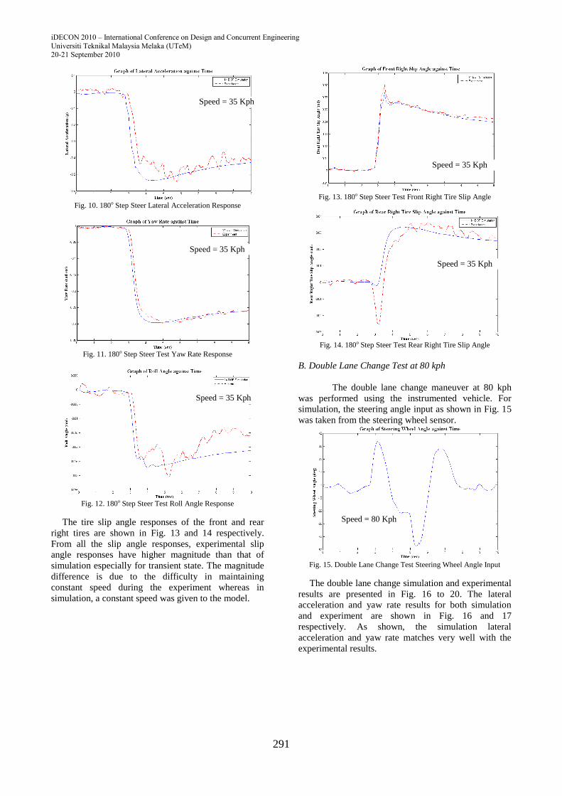
Fig. 10. 180o Step Steer Lateral Acceleration Response
Fig. 11. 180o Step Steer Test Yaw Rate Response
Fig. 12. 180o Step Steer Test Roll Angle Response
The tire slip angle responses of the front and rear
right tires are shown in Fig. 13 and 14 respectively.
From all the slip angle responses, experimental slip
angle responses have higher magnitude than that of
simulation especially for transient state. The magnitude
difference is due to the difficulty in maintaining
constant speed during the experiment whereas in
simulation, a constant speed was given to the model.
Fig. 13. 180o Step Steer Test Front Right Tire Slip Angle
Fig. 14. 180o Step Steer Test Rear Right Tire Slip Angle
B. Double Lane Change Test at 80 kph
The double lane change maneuver at 80 kph
was performed using the instrumented vehicle. For
simulation, the steering angle input as shown in Fig. 15
was taken from the steering wheel sensor.
Fig. 15. Double Lane Change Test Steering Wheel Angle Input
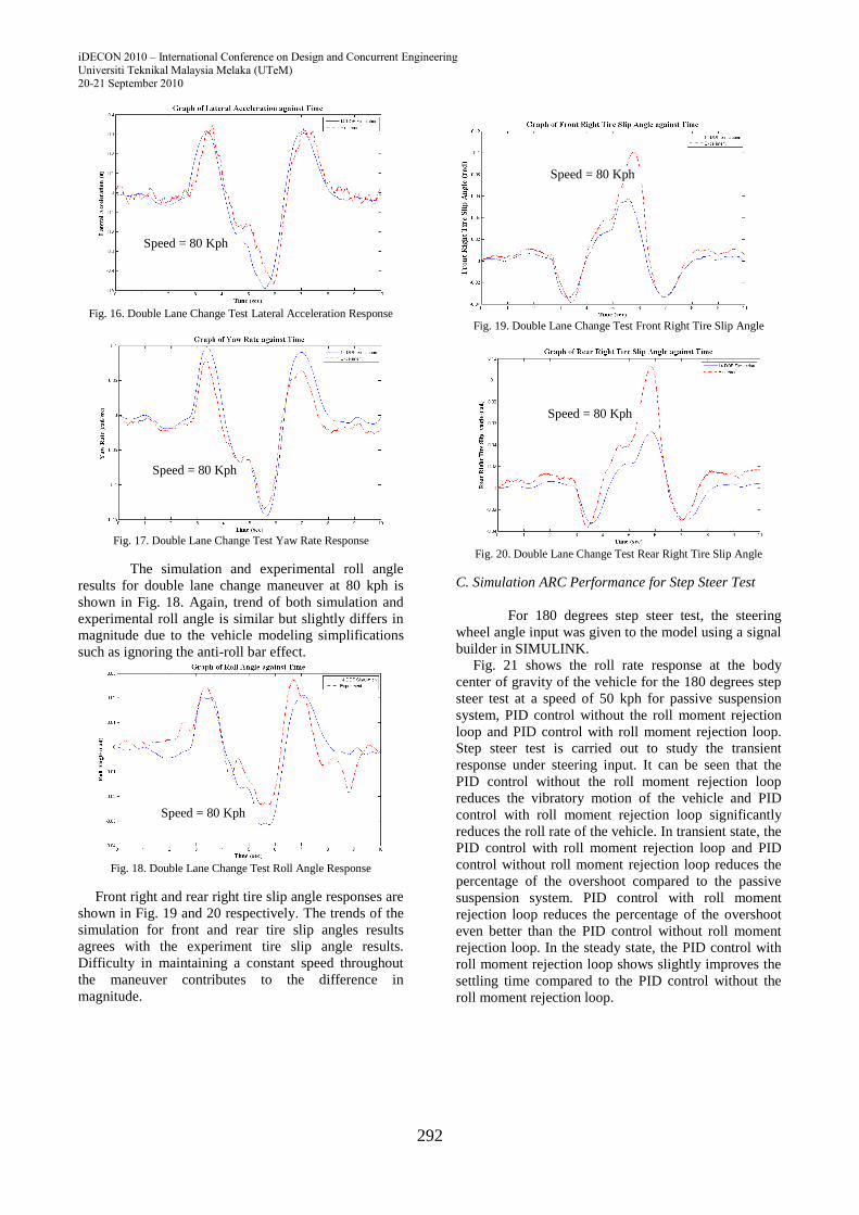
The double lane change simulation and experimental
results are presented in Fig. 16 to 20. The lateral
acceleration and yaw rate results for both simulation
and experiment are shown in Fig. 16 and 17
respectively. As shown, the simulation lateral
acceleration and yaw rate matches very well with the
experimental results.
Speed = 35 Kph
Speed = 35 Kph
Speed = 35 Kph
Speed = 35 Kph
Speed = 80 Kph
Speed = 35 Kph
iDECON 2010 – International Conference on Design and Concurrent Engineering
Universiti Teknikal Malaysia Melaka (UTeM) 20-21 September 2010
292
Fig. 16. Double Lane Change Test Lateral Acceleration Response
Fig. 17. Double Lane Change Test Yaw Rate Response
The simulation and experimental roll angle
results for double lane change maneuver at 80 kph is
shown in Fig. 18. Again, trend of both simulation and
experimental roll angle is similar but slightly differs in
magnitude due to the vehicle modeling simplifications
such as ignoring the anti-roll bar effect.
Fig. 18. Double Lane Change Test Roll Angle Response
Front right and rear right tire slip angle responses are
shown in Fig. 19 and 20 respectively. The trends of the
simulation for front and rear tire slip angles results
agrees with the experiment tire slip angle results.
Difficulty in maintaining a constant speed throughout
the maneuver contributes to the difference in
magnitude.
Fig. 19. Double Lane Change Test Front Right Tire Slip Angle
Fig. 20. Double Lane Change Test Rear Right Tire Slip Angle
C. Simulation ARC Performance for Step Steer Test
For 180 degrees step steer test, the steering
wheel angle input was given to the model using a signal
builder in SIMULINK.
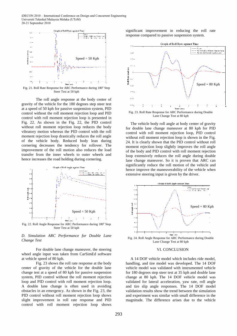
Fig. 21 shows the roll rate response at the body
center of gravity of the vehicle for the 180 degrees step
steer test at a speed of 50 kph for passive suspension
system, PID control without the roll moment rejection
loop and PID control with roll moment rejection loop.
Step steer test is carried out to study the transient
response under steering input. It can be seen that the
PID control without the roll moment rejection loop
reduces the vibratory motion of the vehicle and PID
control with roll moment rejection loop significantly
reduces the roll rate of the vehicle. In transient state, the
PID control with roll moment rejection loop and PID
control without roll moment rejection loop reduces the
percentage of the overshoot compared to the passive
suspension system. PID control with roll moment
rejection loop reduces the percentage of the overshoot
even better than the PID control without roll moment
rejection loop. In the steady state, the PID control with
roll moment rejection loop shows slightly improves the
settling time compared to the PID control without the
roll moment rejection loop.
Speed = 80 Kph
Speed = 80 Kph
Speed = 80 Kph
Speed = 80 Kph
Speed = 80 Kph
iDECON 2010 – International Conference on Design and Concurrent Engineering
Universiti Teknikal Malaysia Melaka (UTeM) 20-21 September 2010
293
Fig. 21. Roll Rate Response for ARC Performance during 180o Step
Steer Test at 50 kph
The roll angle response at the body center of
gravity of the vehicle for the 180 degrees step steer test
at a speed of 50 kph for passive suspension system, PID
control without the roll moment rejection loop and PID
control with roll moment rejection loop is presented in
Fig. 22. As shown in the Fig. 22, the PID control
without roll moment rejection loop reduces the body
vibratory motion whereas the PID control with the roll
moment rejection loop drastically reduces the roll angle
of the vehicle body. Reduced body lean during
cornering decreases the tendency for rollover. The
improvement of the roll motion also reduces the load
transfer from the inner wheels to outer wheels and
hence increases the road holding during cornering.
Fig. 22. Roll Angle Response for ARC Performance during 180o Step
Steer Test at 50 kph
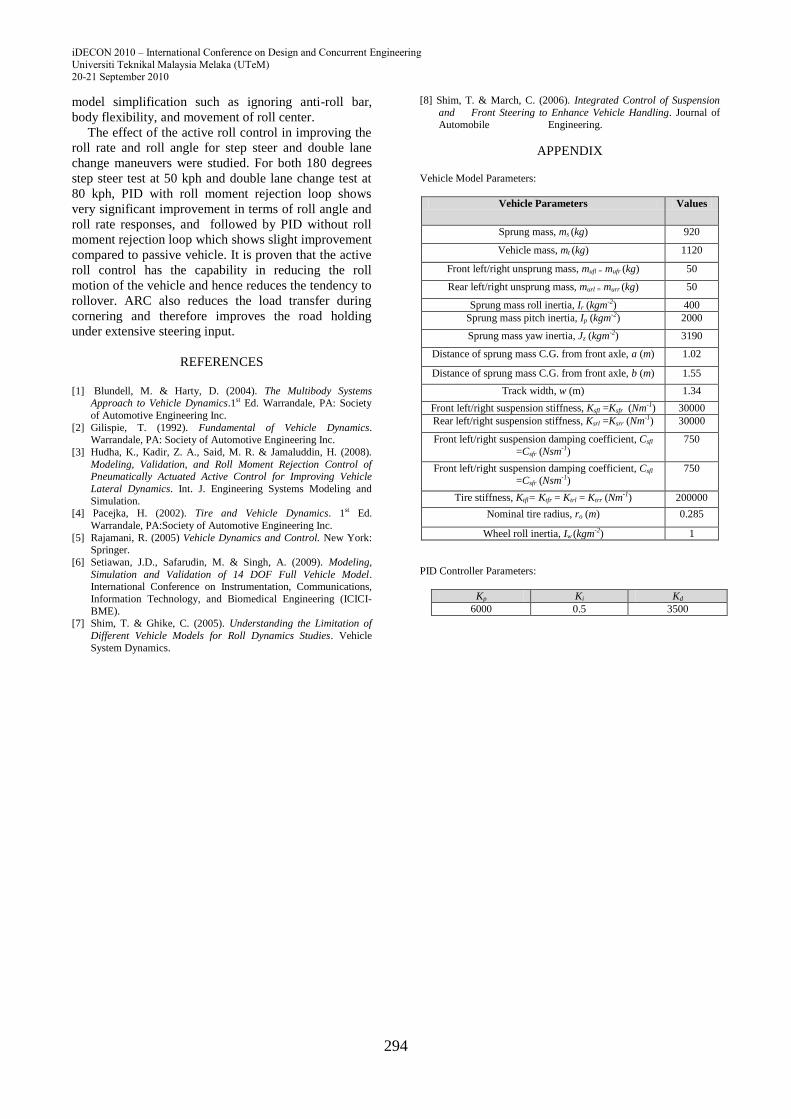
D. Simulation ARC Performance for Double Lane
Change Test
For double lane change maneuver, the steering
wheel angle input was taken from CarSimEd software
at vehicle speed of 80 kph.
Fig. 23 shows the roll rate response at the body
center of gravity of the vehicle for the double lane
change test at a speed of 80 kph for passive suspension
system, PID control without the roll moment rejection
loop and PID control with roll moment rejection loop.
A double lane change is often used in avoiding
obstacles in an emergency. As shown in the Fig. 23, the
PID control without roll moment rejection loop shows
slight improvement in roll rate response and PID
control with roll moment rejection loop shows
significant improvement in reducing the roll rate
response compared to passive suspension system.
Fig. 23. Roll Rate Response for ARC Performance during Double
Lane Change Test at 80 kph
The vehicle body roll angle at body center of gravity
for double lane change maneuver at 80 kph for PID
control with roll moment rejection loop, PID control
without roll moment rejection loop is shown in the Fig.
24. It is clearly shown that the PID control without roll
moment rejection loop slightly improves the roll angle
of the body and PID control with roll moment rejection
loop extensively reduces the roll angle during double
lane change maneuver. So it is proven that ARC can
significantly reduce the roll motion of the vehicle and
hence improve the maneuverability of the vehicle when
extensive steering input is given by the driver.
Fig. 24. Roll Angle Response for ARC Performance during Double
Lane Change Test at 80 kph
VI. CONCLUSION
A 14 DOF vehicle model which includes ride model,
handling, and tire model was developed. The 14 DOF
vehicle model was validated with instrumented vehicle
for 180 degrees step steer test at 35 kph and double lane
change at 80 kph. The 14 DOF vehicle model was
validated for lateral acceleration, yaw rate, roll angle
and tire slip angle responses. The 14 DOF model
validation results show the trend between the simulation
and experiment was similar with small difference in the
magnitude. The difference arises due to the vehicle
Speed = 50 Kph
Speed = 50 Kph
Speed = 80 Kph
Speed = 80 Kph
iDECON 2010 – International Conference on Design and Concurrent Engineering
Universiti Teknikal Malaysia Melaka (UTeM) 20-21 September 2010
294
model simplification such as ignoring anti-roll bar,
body flexibility, and movement of roll center.
The effect of the active roll control in improving the
roll rate and roll angle for step steer and double lane
change maneuvers were studied. For both 180 degrees
step steer test at 50 kph and double lane change test at
80 kph, PID with roll moment rejection loop shows
very significant improvement in terms of roll angle and
roll rate responses, and followed by PID without roll
moment rejection loop which shows slight improvement
compared to passive vehicle. It is proven that the active
roll control has the capability in reducing the roll
motion of the vehicle and hence reduces the tendency to
rollover. ARC also reduces the load transfer during
cornering and therefore improves the road holding
under extensive steering input.
REFERENCES
[1] Blundell, M. & Harty, D. (2004). The Multibody Systems
Approach to Vehicle Dynamics.1st Ed. Warrandale, PA: Society
of Automotive Engineering Inc.
[2] Gilispie, T. (1992). Fundamental of Vehicle Dynamics. Warrandale, PA: Society of Automotive Engineering Inc.
[3] Hudha, K., Kadir, Z. A., Said, M. R. & Jamaluddin, H. (2008).
Modeling, Validation, and Roll Moment Rejection Control of Pneumatically Actuated Active Control for Improving Vehicle
Lateral Dynamics. Int. J. Engineering Systems Modeling and
Simulation. [4] Pacejka, H. (2002). Tire and Vehicle Dynamics. 1st Ed.
Warrandale, PA:Society of Automotive Engineering Inc.
[5] Rajamani, R. (2005) Vehicle Dynamics and Control. New York: Springer.
[6] Setiawan, J.D., Safarudin, M. & Singh, A. (2009). Modeling,
Simulation and Validation of 14 DOF Full Vehicle Model. International Conference on Instrumentation, Communications,
Information Technology, and Biomedical Engineering (ICICI-
BME).
[7] Shim, T. & Ghike, C. (2005). Understanding the Limitation of
Different Vehicle Models for Roll Dynamics Studies. Vehicle
System Dynamics.
[8] Shim, T. & March, C. (2006). Integrated Control of Suspension
and Front Steering to Enhance Vehicle Handling. Journal of
Automobile Engineering.
APPENDIX Vehicle Model Parameters:
Vehicle Parameters Values
Sprung mass, ms (kg) 920
Vehicle mass, mt (kg) 1120
Front left/right unsprung mass, mufl = mufr (kg) 50
Rear left/right unsprung mass, murl = murr (kg) 50
Sprung mass roll inertia, Ir (kgm-2) 400
Sprung mass pitch inertia, Ip (kgm-2) 2000
Sprung mass yaw inertia, Jz (kgm-2) 3190
Distance of sprung mass C.G. from front axle, a (m) 1.02
Distance of sprung mass C.G. from front axle, b (m) 1.55
Track width, w (m) 1.34
Front left/right suspension stiffness, Ksfl =Ksfr (Nm-1) 30000
Rear left/right suspension stiffness, Ksrl =Ksrr (Nm-1) 30000
Front left/right suspension damping coefficient, Csfl
=Csfr (Nsm-1)
750
Front left/right suspension damping coefficient, Csfl =Csfr (Nsm-1)
750
Tire stiffness, Ktfl= Ktfr = Ktrl = Ktrr (Nm-1) 200000
Nominal tire radius, ro (m) 0.285
Wheel roll inertia, Iw (kgm-2) 1
PID Controller Parameters:
Kp Ki Kd
6000 0.5 3500