
MODELING STUDY OF A GAS TURBINE BURNER...
24
MODELING STUDY OF A GAS TURBINE BURNER COOLING RING EFFICIENCY IN A MODEL COMBUSTOR EXIT DUCT SUHAILA BINTI MAT SAID UNIVERSITI TEKNIKAL MALAYSIA MELAKA
Transcript of MODELING STUDY OF A GAS TURBINE BURNER...

MODELING STUDY OF A GAS TURBINE BURNER COOLING RING
EFFICIENCY IN A MODEL COMBUSTOR EXIT DUCT
SUHAILA BINTI MAT SAID
UNIVERSITI TEKNIKAL MALAYSIA MELAKA
PENGESAHAN PENYELIA
“ Saya akui bahawa saya telah membaca
karya ini dan pada pandangan saya karya ini
adalah memadai dari segi skop dan kualiti untuk tujuan penganugerahan
Ijazah Sarjana Muda Kejuruteraan Mekanikal (Automotif)”
Tandatangan :……………………………
Nama Penyelia I
: PN. MAHANUM BINTI
MOHD ZAMBERI
Tarikh : MEI 2010
Tandatangan :…………………………………..
Nama Penyelia II
: EN. WAN ZAILIMI BIN WAN
ABDULLAH
Tarikh : MEI 2010
MODELING STUDY OF A GAS TURBINE BURNER COOLING RING EFFICIENCY IN A
MODEL COMBUSTOR EXIT DUCT
SUHAILA BINTI MAT SAID
Laporan ini dikemukakan sebagai
memenuhi syarat sebahagian daripada syarat penganugerahan
Ijazah Sarjana Muda Kejuruteraan Mekanikal (Automotif)
Fakulti Kejuruteraan Mekanikal
Universiti Teknikal Malaysia Melaka
MEI 2010
ii
“I hereby to declare that this project report entitled MODELING STUDY OF A GAS
TURBINE BURNER COOLING RING EFFICIENCY IN A MODEL COMBUSTOR
EXIT DUCT is written by me and is my own effort except the ideas and summaries
which I have clarified sources”
Signature : …………….…………………
Author : SUHAILA BINTI MAT SAID
Date : MAY 2010

iii
“Dedicated to my lovely parents, family, friends and lecturers who has been supportive
and give encouragement throughout my whole life”
iv
ACKNOWLEDGEMENTS
First of all, I would like to express my thankfulness to Allah Almighty for
blessing. I managed to complete this project on time and could submit it to Mechanical
Engineering Faculty of University Technical Malaysia Malacca (UTeM) to fulfill the
requirements of my Bachelor in Mechanical of Automotive.
My appreciation is extended to all who provided helpful suggestion to improve
this project. I want to thank to most honored project supervisor, Mrs. Mahanum binti
Mohd Zamberi for her guidance during this project. Besides, I also would like to thank
her for willing to spend her convenience times for giving advices along project was
conducted.
I also would like to send my appreciation toward my course mates and
housemates, Alwani, Saiful Azhar, Noor Asmah, Muhyiddin, Izzati Mahirah, Nur Izrin,
Dila Afnida who had contributed some comments and suggestion in this project. Last
but not least, to my beloved families for unlimited support and tolerance in completing
my project. Without all the helps provided, this project might not proceed smoothly.
Lastly, thank you to all.
v
ABSTRACT
The main purpose of this study is to increase the efficiency of gas turbine
burner cooling ring in a model combustor exit duct. The Computational Fluid Dynamics
(CFD) package of FLUENT will use to simulate 2D cooling ring model. The modeling
of burner cooling ring is taken under turbulence models of two equation model, which
are turbulent kinetic energy, k and the energy dissipation, ε or known as standard k-
epsilon model. The cooling ring effectiveness is dependent upon the approach flow
turbulence; the temperature; velocity distribution; and the blade and cooling ring
geometry. The 2D geometry of a gas turbine cooling ring is built up with suitable grid to
determine the heat coefficient and its effectiveness. There are 3 cases during this study;
the cooling ring efficiency is investigated at fixed velocity of 10 m/s and the turbulence
intensity, α between 5% to 25%, and the other one is at fixed turbulence intensity, α of
10% and varies the value of velocity between 5 m/s to 25 m/s. The third case is by varies
the size of cool air inlet for 10 mm to 40 mm. Both temperature, T at cool air inlet and
hot air inlet is constant at 293 K and 1000 K respectively. In this study the wall is
assumed to be solid wall with adiabatic wall temperature and non-slip boundary
condition. Both pressure inlet and outlet are same. After simulate using CFD, the graph
of cooling ring performance will be obtained. As the result, the most cooling
effectiveness will increase with increasing velocity, decreasing turbulence intensity, with
large size of coolant air inlet.
vi
ABSTRAK
Tujuan utama kajian ini adalah bagi meningkatkan kecekapan salur pendingin di
saluran keluar pembakar pada turbin gas. Simulasi CFD yang menggunakan pakej
FLUENT digunapakai untuk mensimulasikan model salur pendingin dalam model 2D. k-
epsilon model telah dipilih untuk digunakan bagi tujuan mensimulasikan model 2D salur
pendingin ini. Keberkesanan salur pendingin ini adalah bergantung pada aliran
pendekatan turbulent iaitu suhu, pengedaran kelajuan, dan geometri salur pendingin.
Grid yang bersesuaian digunakan pada model 2D salur pendingin agar data yang
diperolehi lebih tepat. Terdapat 3 kes bagi projek ini, dimana yang pertama, kecekapan
salur pendingin pada salur penyejuk ditentukan dengan memalarkan kelajuan pada 10
m/s dan mengubah turbulence intensity, α pada 5% hingga 20%. Manakala bagi kes
kedua pula, turbulence intensity dimalarkan pada 10% dan kelajuannya diubah dari 5
m/s hingga 25 m/s. Bagi kes yang terakhir, saiz salur pendingin ditukar dari 10 mm
hingga 40 mm. Kelajuan dan turbulence intensity ditetapkan pada 10 m/s dan 10%
masing-masing. Untuk ketiga-tiga kes ini, suhu adalar ditetapkan pada 293 K pada
saluran masuk udara sejuk dan 1000 K pada salur masuk udara panas. Dalam kajian ini
juga, dinding bagi salur penyejuk dianggap adiabatic dan tiada kegelinciran yang
berlaku. Manakala, kedua-dua tekanan pada salur masuk dan salur keluar adalah sama.
Setelah disimulasi menggunakan CFD, graf prestasi salur pendingin akan diperolehi.
Keputusan menunjukkan, keberkesanan salur pendingin akan meningkat dengan
meningkatnya kelajuan, kurangnya turbulence intensity, dan ukuran besar bagi saluran
masuk pendingin.
vii
CONTENT
CHAPTER TITLE PAGES
DECLARATION ii
DEDICATION iii
ACKNOWLEDGEMENT iv
ABSTRACT v
ABSTRAK vi
CONTENT vii
LIST OF TABLES x
LIST OF FIGURES xi
LIST OF ABBREVIATIONS xiii
CHAPTER I INTRODUCTION
1.1 Introduction 1
1.2 History of Gas Turbine 3
1.3 Gas Turbine Development 4
1.4 Gas Turbine Theory Operation 6
1.5 Type of Gas Turbine 8
1.6 Blade Cooling 9
1.7 Problem Statement 14
1.8 Objective 15
1.9 Scope of Study 15
viii
CHAPTER TITLE PAGES
CHAPTER II LITERATURE REVIEW
2.1 Boundary Layer 18
2.2 Turbulence Intensity 22
2.3 Reynolds’ Number 23
2.4 Conservation Law of Fluid Motion 25
2.5 Navier Stokes Equation 25
2.6 Turbulence Modeling 26
CHAPTER III METHODOLOGY
3.1 Introduction 33
3.2 Flow Chart 34
3.3 Computational Fluid Dynamics 35
3.4 Assumptions 38
3.5 2D Cooling Ring 39
3.6 Meshing Geometry 40
3.7 Iteration 41
CHAPTER IV RESULTS
4.1 Contour of Static Temperature 43
4.2 Velocity Vector 44
4.3 Static Temperature at the Bottom of Wall 45
4.4 Turbulence Intensity at the Bottom of Wall 46
4.5 Effect of Velocity Coolant Inlet, 47
Turbulence Intensity and Coolant Inlet Size
4.6 Different Coolant Inlet Velocity and 49
Turbulence Intensity
4.7 Cooling Effectiveness 50
ix
CHAPTER TITLE PAGES
CHAPTER V DISCUSSION
5.1 Effect of Coolant Inlet Velocity 54
5.2 Effect of Turbulence Intensity 54
5.3 Effect of Coolant Inlet Slot Size 54
CHAPTER VII CONCLUSION 55
REFERENCE 57
BIBLIOGRAPHY 59
APPENDIX 61
x
LIST OF TABLES
NO. TITLE PAGES
3.4 Properties of cooling ring 39
3.6 Grid and nodes 40
3.7 Converged criterion 41
xi
LIST OF FIGURES
NO. TITLE PAGES
1.1 Cross-Sectional View of a Cooled Vane and Blade 2
Schematic of a Modern Gas Turbine Blade 3
1.2 Current gas turbine 4
1.4 Open cycle for gas turbine 7
Closed cycle for gas turbine 7
1.5 Turbine with regeneration 8
Turbine with intercooling 9
1.6 A typical turbine blade with film cooling holes 10
Cooling holes 10
3D of cooling blade flow 11
Three-dimensional (3D) of cooling blade 12
Two-dimensional (2D) of cooling blade 12
Convection cooling 13
Impingement cooling 13
2.1 Flow meets the leading edge 18
Layers meet at the centre 18
Velocity profile 18
2.3 Scale effect 24
3.3 CFD insight into the effect of breathing 37
Simulation of flow over male elite swimmer 37
Turbulent mixing inside a rotating impeller 38
xii
NO. TITLE
3.5 Cooling ring 39
3.6 Meshing Geometry 40
3.7 Converged iteration 41
4.1 Contours of static temperature (K) 43
4.2 Vector velocity 44
4.3 Temperature of the wall 45
4.4 Turbulence Intensity of the wall 46
4.5 Wall Temperature versus Coolant Inlet Velocity 47
Wall Temperature versus Coolant Inlet Turbulence Intensity 48
Wall Temperature versus Coolant Inlet Size 49
4.6 Best static temperature contour 49
Bad static temperature contour 50
4.7 Cooling Efficiency versus Coolant Inlet Velocity 50
Cooling Efficiency versus Coolant Inlet turbulence intensity 51
Cooling Efficiency versus Coolant Inlet size 51
xiii
LIST OF ABBREVIATIONS
°C = Degree Celcius
2D = Two Dimensional
3D = Three Dimensional
BL = Boundary
CFD = Computational Fluid Dynamics
DNS = Direct Numerical Simulation
FEA = Finite Element Analysis
GAMBIT = Geometry and Meshing Building Intelligent Toolkit
HP = Horse Power
HVAC = Heating Ventilation Air Conditioning
K = Kelvin
k-ε = k-epsilon
LES = Large-Eddy Simulation
m/s = Metre per second
Mm = Milimetre
PDE = Partial Differential Equation
RANS = Reynolds Averaged Navier-Stokes
RSM = Reynolds Stress Models
1
CHAPTER 1
INTRODUCTION
1.1 Introduction
Gas turbines play a vital role in the today’s industrialized society, and as the
demands for power increase, the power output and thermal efficiency of gas turbines
must also increase. One method of increasing both the power output and thermal
efficiency of the engine is to increase the temperature of the gas entering the turbine.
In the advanced gas turbines of today, the turbine inlet temperature can be as
high as 1500°C. However, this temperature exceeds the melting temperature of the metal
airfoils. Therefore, it is imperative that the blades and vanes are cooled, so they can
withstand these extreme temperatures. Cooling air around 650°C is extracted from the
compressor and passes through the airfoils. With the hot gases and cooling air, the
temperature of the blades can be lowered to approximately 1000°C, which is permissible
for reliable operation of the engine. It is widely accepted that the life of a turbine blade
can be reduced by half if the temperature prediction of the metal blade is off by only
30°C.
In order to avoid premature failure, designers must accurately predict the local
heat transfer coefficient of metal temperatures. By preventing local hot spots, the life of
the turbine blades and vanes will increase. However, due to the complex flow around the
airfoils it is difficult for designers to accurately predict the metal temperature.
2
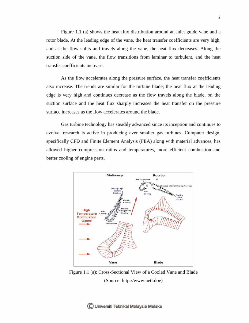
Figure 1.1 (a) shows the heat flux distribution around an inlet guide vane and a
rotor blade. At the leading edge of the vane, the heat transfer coefficients are very high,
and as the flow splits and travels along the vane, the heat flux decreases. Along the
suction side of the vane, the flow transitions from laminar to turbulent, and the heat
transfer coefficients increase.
As the flow accelerates along the pressure surface, the heat transfer coefficients
also increase. The trends are similar for the turbine blade; the heat flux at the leading
edge is very high and continues decrease as the flow travels along the blade, on the
suction surface and the heat flux sharply increases the heat transfer on the pressure
surface increases as the flow accelerates around the blade.
Gas turbine technology has steadily advanced since its inception and continues to
evolve; research is active in producing ever smaller gas turbines. Computer design,
specifically CFD and Finite Element Analysis (FEA) along with material advances, has
allowed higher compression ratios and temperatures, more efficient combustion and
better cooling of engine parts.
Figure 1.1 (a): Cross-Sectional View of a Cooled Vane and Blade
(Source: http://www.netl.doe)
3
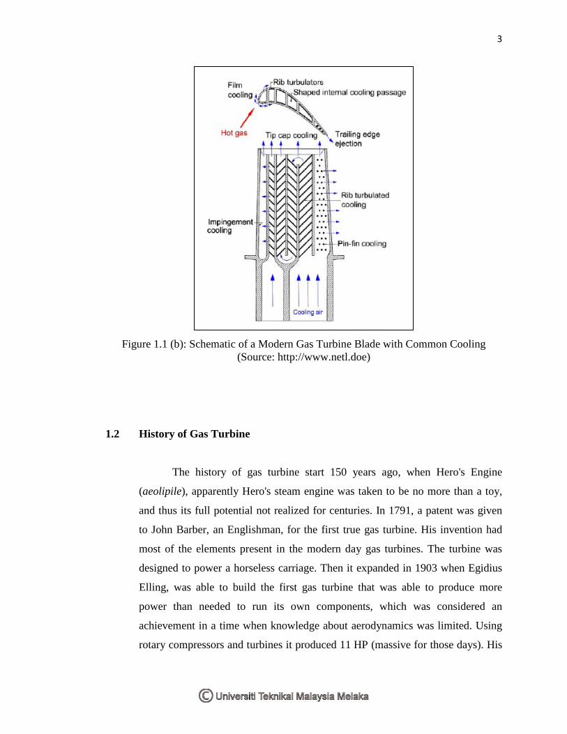
Figure 1.1 (b): Schematic of a Modern Gas Turbine Blade with Common Cooling
(Source: http://www.netl.doe)
1.2 History of Gas Turbine
The history of gas turbine start 150 years ago, when Hero's Engine
(aeolipile), apparently Hero's steam engine was taken to be no more than a toy,
and thus its full potential not realized for centuries. In 1791, a patent was given
to John Barber, an Englishman, for the first true gas turbine. His invention had
most of the elements present in the modern day gas turbines. The turbine was
designed to power a horseless carriage. Then it expanded in 1903 when Egidius
Elling, was able to build the first gas turbine that was able to produce more
power than needed to run its own components, which was considered an
achievement in a time when knowledge about aerodynamics was limited. Using
rotary compressors and turbines it produced 11 HP (massive for those days). His
4
work was later used by Sir Frank Whittle. 1930: Sir Frank Whittle patented the
design for a gas turbine for jet propulsion. His work on gas propulsion relied on
the work from all those who had previously worked in the same field and he has
himself stated that his invention would be hard to achieve without the works of
Egidius Elling. The first successful use of his engine was in April 1937.
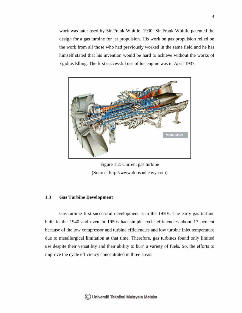
Figure 1.2: Current gas turbine
(Source: http://www.doosanheavy.com)
1.3 Gas Turbine Development
Gas turbine first successful development is in the 1930s. The early gas turbine
built in the 1940 and even in 1950s had simple cycle efficiencies about 17 percent
because of the low compressor and turbine efficiencies and low turbine inlet temperature
due to metallurgical limitation at that time. Therefore, gas turbines found only limited
use despite their versatility and their ability to burn a variety of fuels. So, the efforts to
improve the cycle efficiency concentrated in three areas:
5
a. Increasing the turbine inlet (or firing) temperatures: This has been the primary
approach taken to improve gas turbine efficiency. The turbine inlet temperatures
have increased steadily from 540 ˚C in the 1940s to 1425 ˚C and even higher
today. These increases were made possible by the development of new materials
and the innovative cooling technique for the critical components such as coating
the turbine blades with ceramic layer and cooling the blade with the discharge air
from the compressor. Maintaining high turbine inlet temperatures with an air-
cooling technique requires the combustion temperature to be higher to
compensate for the cooling effect of the cooling air.
b. Increasing the efficiencies of turbomachinery components: The performance of
early turbines suffered greatly from the inefficiencies of turbines and
compressors. However, the advent of computers and advanced techniques for
computer-aided design made it possible to design these components
aerodynamically with minimal losses. The increased efficiencies of the turbines
and compressors resulted in a significant increase in the cycle efficiency.
c. Adding modifications to the basic cycle: The simple-cycle efficiencies of early
gas turbine were practically doubled by incorporating intercooling, regeneration
(or recuperation), and reheating. These improvements, of course, come of
expand of increased the initial and operation costs, and they cannot be justified
unless the decrease in fuel costs offsets the increase in the other cost. The
relatively low fuel prices, the general desire in the industry to minimize
installation costs, and the tremendous increase in the simple-cycle efficiency to
about 40 percent left desire for opting for these modifications. [1]
6
1.4 Gas Turbine Theory of Operation
The Brayton cycle was first proposed by George Brayton for use in the
reciprocating oil burning engine that he developed around 1870. Today, it is used for gas
turbines only where both the compression and expansion processes take place in rotating
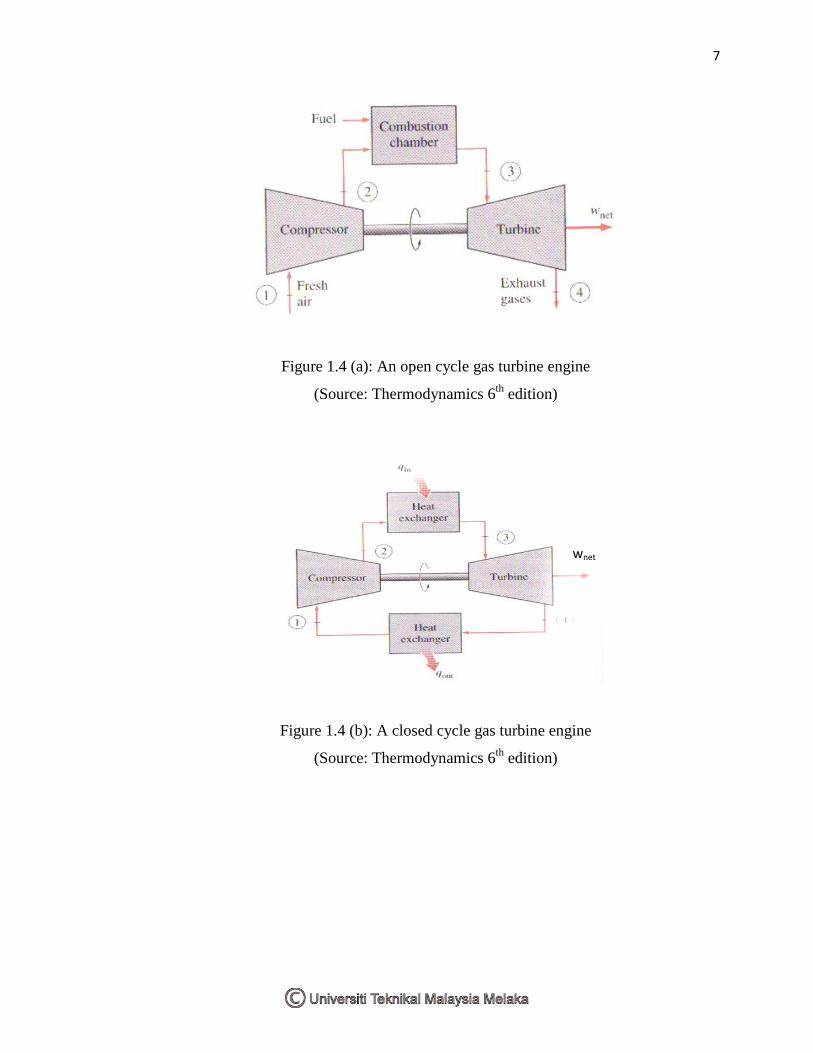
machinery. Gas turbines usually operate on an open cycle, as shown in figure 1.4 (a).
The fresh air at ambient condition is drawn into the compressor, where its temperature
and pressure raised.
The high pressure air proceeds into the combustion chamber, where the fuel is
burned at constant pressure. The resulting high-temperature gases than enter the turbine,
where they expand to the atmospheric pressure while producing power. The exhaust
gases leaving the turbine are thrown out (not recirculated), causing the cycle to be
classified as an open cycle.
The open gas turbine cycle described above can be modeled as a closed cycle, as
shown in figure 1.4 (b), by utilizing the air-standard assumptions. Here the compression
and expansion processes remain the same, but the combustion process is replaced by a
constant-pressure heat-addition process from an external source, and the exhaust process
is replaced by a constant pressure heat-rejection process to the ambient air. The ideal
cycle that the working fluid undergoes in this closed loops in the Brayton cycle, which is
made up of four internally reversible processes:
a. Isentropic compression (in a compressor)
b. Constant- pressure heat addition
c. Isentropic expansion (in a turbine)
d. Constant- pressure heat rejection
7
Figure 1.4 (a): An open cycle gas turbine engine
(Source: Thermodynamics 6th edition)
Figure 1.4 (b): A closed cycle gas turbine engine
(Source: Thermodynamics 6th edition)
wnet
8
1.5 Type of Gas Turbine
There are three main section of a simple gas turbine, which consists of a
compressor, a combustor, and a power turbine. In a simple gas turbine cycle, low
pressure air is drawn into a compressor (state 1) where it is compressed to a higher
pressure (state 2). Fuel is added to the compressed air and the mixture is burnt in a
combustion chamber. The resulting hot products enter the turbine (state 3) and expand to
state 4. Most of the work produced in the turbine is used to run the compressor and the
rest is used to run auxiliary equipment and produce power.
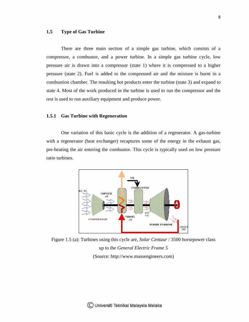
1.5.1 Gas Turbine with Regeneration
One variation of this basic cycle is the addition of a regenerator. A gas-turbine
with a regenerator (heat exchanger) recaptures some of the energy in the exhaust gas,
pre-heating the air entering the combustor. This cycle is typically used on low pressure
ratio turbines.
Figure 1.5 (a): Turbines using this cycle are, Solar Centaur / 3500 horsepower class
up to the General Electric Frame 5
(Source: http://www.massengineers.com)
9
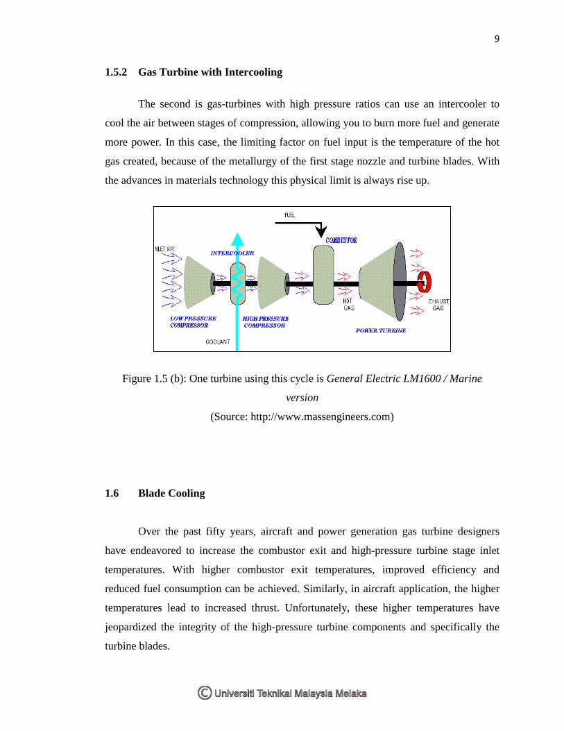
1.5.2 Gas Turbine with Intercooling
The second is gas-turbines with high pressure ratios can use an intercooler to
cool the air between stages of compression, allowing you to burn more fuel and generate
more power. In this case, the limiting factor on fuel input is the temperature of the hot
gas created, because of the metallurgy of the first stage nozzle and turbine blades. With
the advances in materials technology this physical limit is always rise up.
Figure 1.5 (b): One turbine using this cycle is General Electric LM1600 / Marine
version
(Source: http://www.massengineers.com)
1.6 Blade Cooling
Over the past fifty years, aircraft and power generation gas turbine designers
have endeavored to increase the combustor exit and high-pressure turbine stage inlet
temperatures. With higher combustor exit temperatures, improved efficiency and
reduced fuel consumption can be achieved. Similarly, in aircraft application, the higher
temperatures lead to increased thrust. Unfortunately, these higher temperatures have
jeopardized the integrity of the high-pressure turbine components and specifically the
turbine blades.