PROCEEDINGS OF SMART SECURITY SYSTEM
79
Transcript of PROCEEDINGS OF SMART SECURITY SYSTEM
i
PROCEEDINGS OF ELECTRICAL ENGINEERING CAPSTONE SHOWCASE
(EECS 2020)
SMART SECURITY SYSTEM
ii
PROCEEDINGS OF ELECTRICAL ENGINEERING CAPSTONE SHOWCASE 2020: SMART SECURITY SYSTEM
2021
First Edition 2021
Hak cipta terpelihara. Tiada dibenarkan mengeluar ulang mana-mana bahagian artikel, ilustrasi dan isi kandungan buku ini dalam apa juga bentuk dan cara apa jua sama ada dengan cara elektronik, fotokopi, mekanik, atau cara lain sebelum mendapat keizinan bertulis dari Pengerusi, Sekolah Kejuruteraan Elektrik, Universiti Teknologi Malaysia, 81310 UTM Johor Bahru, Johor Darul Ta’zim, Malaysia. Perundingan tertakluk kepada perkiraan royalti atau honorarium. All right reserved. No part of this proceedings may be reproduced, or transmitted in any form or by any means, electronic or mechanical including photocopying, recording, or any information storage and retrieval system, without permission of Chair, School of Electrical Engineering, Universiti Teknologi Malaysia, 81310 UTM Johor Bahru, Johor Darul Ta’zim, Malaysia. Negotiation is subjected to royalty or honorarium estimation. Published by: School of Electrical Engineering, Universiti Teknologi Malaysia, 81310, Johor Bahru, Malaysia. eISBN 978-967-25669-4-6
iii
CONTENTS
Preface Page Paper 1 GPS-based Asset Tracking for Lab Equipment
Nurhazimah Ghazali, Md Mahfuzur Rahman, Putera Muhd Aiman Danial Saafie, Azizul Hakimi Abd Mutalib, Noor Asniza Murad
1 - 13
Paper 2 Lab Equipment Security and Management System
Nurshadila Binti Zainol, Mohammed Ahmed Mohsen Al-Amoodi, Muhammad Harith Bin Bahrin, Ashraf Aminin Bin Arman Alim, Mohd Haniff Bin Ibrahim
15 – 33
Paper 3 IoT based Anti-Theft System
Thulasy A/P Chandran, Bosco Chan Hsien Qing, Long Muhammad Ilyas Bin Long Zor, Ahmad Arif Zahrin Bin Md Tajuddin, Nur Affina binti Jamalullail, Mohd Fairus Mohd Yusoff
34 - 49
Paper 4 Smart Security Door
Andi Almer Andromeda Rayhan, Tan Zheng Hong, Muhammad Alif bin Mohd Khalil, Muhammad Aidil Azroy bin Azman, Siti Zaleha Abdul Hamid
50 - 60
Paper 5 Theft Detector Security System
Umi Nur Idayu Binti Mohd Hisham, Yousof Mamdouh Mohamed Eldesouky, Muhammad Iqbal Aiman Bin Md. Yazid, Zul Hisyam Bin Mohamad, Nur Affina binti Jamalullail, Dr. Mohd Rashidi Bin Salim
61 - 73
iv
PREFACE
This publication consists of all the research work presented during Electrical Engineering Showcase 2021 which held virtually on 25th January 2021. The research topic is mainly discussing about Smart Security System which has been implemented in residence facilities, educational properties or industrial plants. This annual showcase serves as a platform for undergraduate final year students to share their original, creative and innovative product and research work in a team which supervised by the lecturers. This publication intends to consolidate all the presented product and works, especially in Smart Security System so that it can be used for future reference and to be disseminated among research community in the area of electrical engineering.
Editor Dr. Rashidah Arsat EECS Technical/ COMM Publication/Sub-Editors Team Dr. Nik Noordini Nik Abd. Malik Dr. Noor Asmawati Samsuri Assoc. Prof. Dr. Nurul Mu’azzah Abdul Latiff Dr. Arnidza Ramli Dr. Lim Cheng Siong Dr. Musa Mohd Mokji Dr. Suhana Mohamed Sultan Dr. Zulkarnain Ahmad Noorden Cik. Nur Affina Jamalullail Cik. Shafira Attasha Shamsul Amir
GPS-based Asset Tracking for Lab Equipment
Nurhazimah Ghazali Md Mahfuzur Rahman
Putera Muhd Aiman Danial Saafie Azizul Hakimi Abd Mutalib
Noor Asniza Murad Universiti Teknologi Malaysia
Abstract: Asset tracking device is popular nowadays to track the location of mobile assets such as containers, machines, crates and other equipment even in remote locations. In the past, there was only one way to keep track of movable assets: pen and paper. Businesses would keep logbooks of their assets, establishing when something was signed out, into whose custody it was released, and when it could be expected back. Now, there are many technologies invented to track important assets without manual labour. Some technologies like GPS, Barcode, RFID, IoT and others are used. In this project, the use of GPS-based asset tracking system is implemented to track lab equipment in School of Electrical Engineering. Results demonstrate that this technology could help to improve the lab security system by securing lab equipment. Data from customers such as lecturers and lab technicians was obtained through Google Form to analyze problems they faced with the lab security system. The use of Arduino, GPS and GSM modules was used to validate the solution for problems faced by end users.
Keywords: Arduino; GPS; GSM; Asset Tracking
1.1 Introduction The need for tracking of assets is fathomable in our everyday life in every angle. It is for the welfare and
protection of our physical assets. Asset tracking is referred to as management of assets. The systematic assets tracking provides information about the location, status, schedule of maintenance, safety control alarm and other related important information about the physical assets. The tracking can be using barcode scanning, RFID tags and using GPS tracking.
Despite asset tracking is expensive however there are methods of asset tracking that can save your organization time and money where the goal is to maximize asset control efficiency and minimize equipment loss. The tracking system can include mobile/computer tracking, asset management software, barcode scanners and for real time asset tracking RFID, GPS, IoT and other mobile applications are available.
The proper management of asset tracking enables organizations to schedule necessary maintenance and services. A complete asset tracking system includes scanning barcode labels or reading GPS or RFID tags which are attached to assets to scan their fixed assets to track them accurately and efficiently.
In our project we are using GPS based asset tracking systems for lab equipment inside UTM which is a standard system for data collection and asset tracking, giving each asset a unique identifier so that they are individually recognized and tracked. Our product accessibility is very easy to use, accuracy is around 80%, 70% users are very happy with the quality and prices and it will result in reduction of lab management costs for UTM.
2
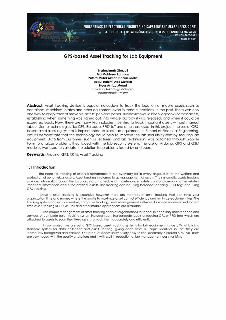
An overview of our tracking system working principle is show in below:
Figure 1: General Overview of Asset Tracking System Working Principle [4]
1.2 Objectives The objective of this project is to create a tracking device that can track the location of the lab equipment by
using GPS in real time. By completing this project, laboratory assistants can easily check the lab equipment regularly and just need to send a message to the sim number that has been installed in the GSM module to get the current location of the lab equipment.
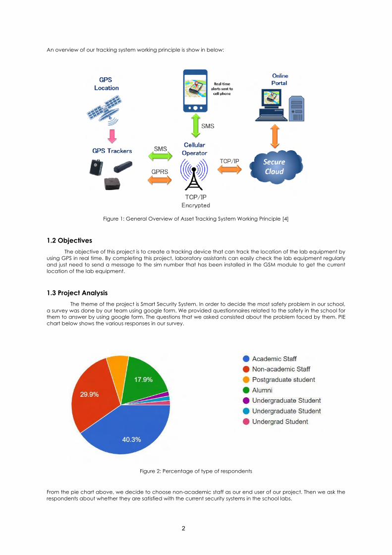
1.3 Project Analysis The theme of the project is Smart Security System. In order to decide the most safety problem in our school,
a survey was done by our team using google form. We provided questionnaires related to the safety in the school for them to answer by using google form. The questions that we asked consisted about the problem faced by them. PIE chart below shows the various responses in our survey.
Figure 2: Percentage of type of respondents
From the pie chart above, we decide to choose non-academic staff as our end user of our project. Then we ask the respondents about whether they are satisfied with the current security systems in the school labs.
3
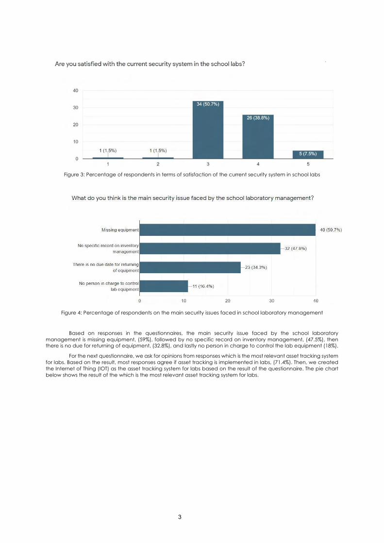
Figure 3: Percentage of respondents in terms of satisfaction of the current security system in school labs
Figure 4: Percentage of respondents on the main security issues faced in school laboratory management
Based on responses in the questionnaires, the main security issue faced by the school laboratory management is missing equipment, (59%), followed by no specific record on inventory management, (47.5%), then there is no due for returning of equipment, (32.8%), and lastly no person in charge to control the lab equipment (18%).
For the next questionnaire, we ask for opinions from responses which is the most relevant asset tracking system for labs. Based on the result, most responses agree if asset tracking is implemented in labs, (71.4%). Then, we created the Internet of Thing (IOT) as the asset tracking system for labs based on the result of the questionnaire. The pie chart below shows the result of the which is the most relevant asset tracking system for labs.
4
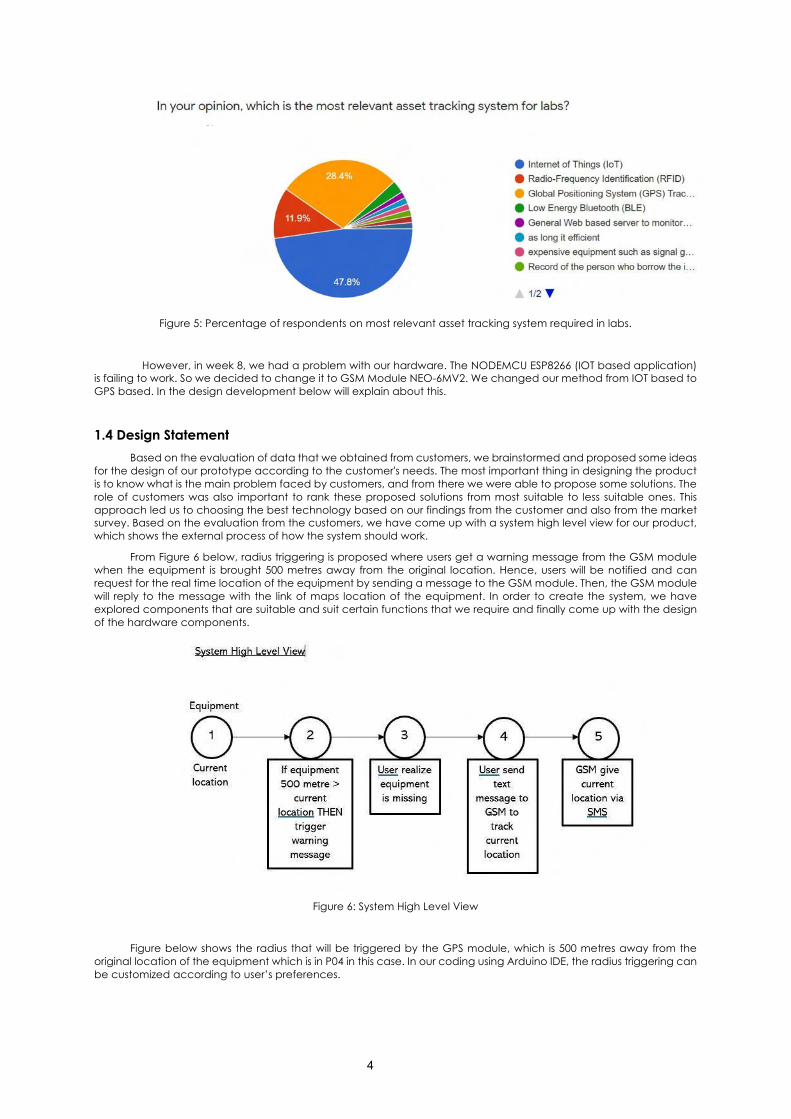
Figure 5: Percentage of respondents on most relevant asset tracking system required in labs.
However, in week 8, we had a problem with our hardware. The NODEMCU ESP8266 (IOT based application) is failing to work. So we decided to change it to GSM Module NEO-6MV2. We changed our method from IOT based to GPS based. In the design development below will explain about this.
1.4 Design Statement Based on the evaluation of data that we obtained from customers, we brainstormed and proposed some ideas
for the design of our prototype according to the customer's needs. The most important thing in designing the product is to know what is the main problem faced by customers, and from there we were able to propose some solutions. The role of customers was also important to rank these proposed solutions from most suitable to less suitable ones. This approach led us to choosing the best technology based on our findings from the customer and also from the market survey. Based on the evaluation from the customers, we have come up with a system high level view for our product, which shows the external process of how the system should work.
From Figure 6 below, radius triggering is proposed where users get a warning message from the GSM module when the equipment is brought 500 metres away from the original location. Hence, users will be notified and can request for the real time location of the equipment by sending a message to the GSM module. Then, the GSM module will reply to the message with the link of maps location of the equipment. In order to create the system, we have explored components that are suitable and suit certain functions that we require and finally come up with the design of the hardware components.
Figure 6: System High Level View
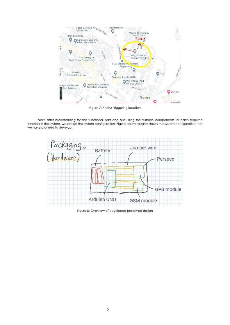
Figure below shows the radius that will be triggered by the GPS module, which is 500 metres away from the original location of the equipment which is in P04 in this case. In our coding using Arduino IDE, the radius triggering can be customized according to user’s preferences.
5
Figure 7: Radius triggering location
Next, after brainstorming for the functional part and discussing the suitable components for each required function in the system, we design the system configuration. Figure below roughly shows the system configuration that we have planned to develop.
Figure 8: Overview of developed prototype design
6
1.5 Methodology
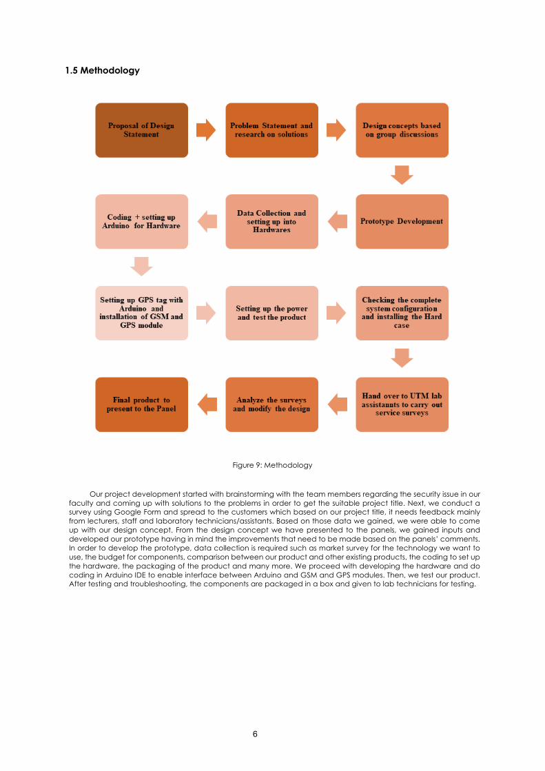
Figure 9: Methodology
Our project development started with brainstorming with the team members regarding the security issue in our faculty and coming up with solutions to the problems in order to get the suitable project title. Next, we conduct a survey using Google Form and spread to the customers which based on our project title, it needs feedback mainly from lecturers, staff and laboratory technicians/assistants. Based on those data we gained, we were able to come up with our design concept. From the design concept we have presented to the panels, we gained inputs and developed our prototype having in mind the improvements that need to be made based on the panels’ comments. In order to develop the prototype, data collection is required such as market survey for the technology we want to use, the budget for components, comparison between our product and other existing products, the coding to set up the hardware, the packaging of the product and many more. We proceed with developing the hardware and do coding in Arduino IDE to enable interface between Arduino and GSM and GPS modules. Then, we test our product. After testing and troubleshooting, the components are packaged in a box and given to lab technicians for testing.
7
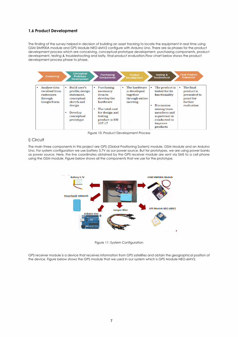
1.6 Product Development
The finding of the survey helped in decision of building an asset tracking to locate the equipment in real time using GSM SIM900A module and GPS Module NEO-6MV2 configure with Arduino Uno. There are six phases for the product development process which are conceiving, conceptual prototype development, purchasing components, product development, testing & troubleshooting and lastly, final product evaluation.Flow chart below shows the product development process phase to phase.
Figure 10: Product Development Process
i) Circuit The main three components in this project are GPS (Global Positioning System) module, GSM Module and an Arduino Uno. For system configuration we use battery 3.7V as our power source. But for prototypes, we are using power banks as power source. Here, the live coordinates obtained by the GPS receiver module are sent via SMS to a cell phone using the GSM module. Figure below shows all the components that we use for the prototype.
Figure 11: System Configuration
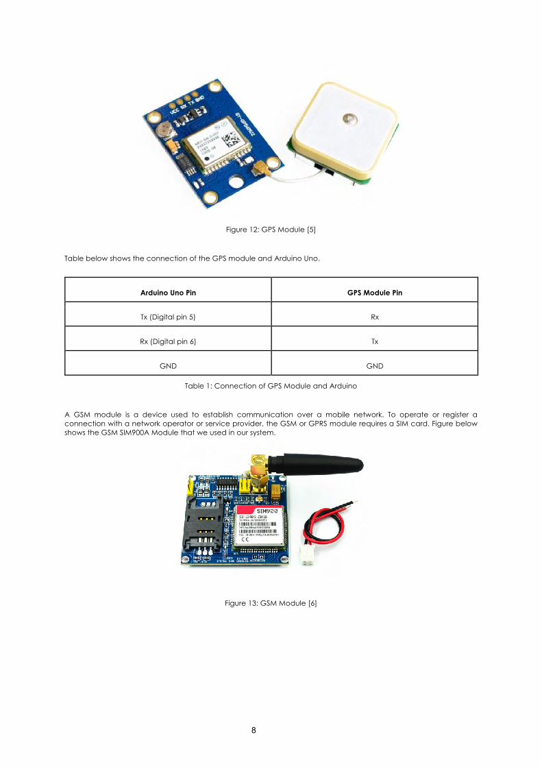
GPS receiver module is a device that receives information from GPS satellites and obtain the geographical position of the device. Figure below shows the GPS module that we used in our system which is GPS Module NEO-6MV2.
8
Figure 12: GPS Module [5]
Table below shows the connection of the GPS module and Arduino Uno.
Arduino Uno Pin GPS Module Pin
Tx (Digital pin 5) Rx
Rx (Digital pin 6) Tx
GND GND
Table 1: Connection of GPS Module and Arduino
A GSM module is a device used to establish communication over a mobile network. To operate or register a connection with a network operator or service provider, the GSM or GPRS module requires a SIM card. Figure below shows the GSM SIM900A Module that we used in our system.
Figure 13: GSM Module [6]
9
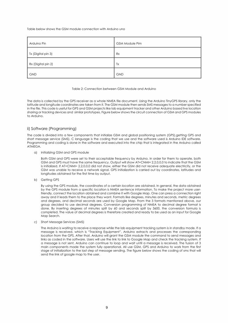
Table below shows the GSM module connection with Arduino uno
Arduino Pin GSM Module Pim
Tx (Digital pin 3) Rx
Rx (Digital pin 2) Tx
GND GND
Table 2: Connection between GSM Module and Arduino
The data is collected by the GPS receiver as a whole NMEA file document. Using the Arduino TinyGPS library, only the latitude and longitude coordinates are taken from it. The GSM module then sends SMS messages to a number specified in the file. This code is useful for GPS and GSM projects like lab equipment tracker and other Arduino based live location sharing or tracking devices and similar prototypes. Figure below shows the circuit connection of GSM and GPS modules to Arduino.
ii) Software (Programming) The code is divided into a few components that initialize GSM and global positioning system (GPS),getting GPS and short message service (SMS). C language is the coding that we use and the software used is Arduino IDE software. Programming and coding is done in the software and executed into the chip that is integrated in the Arduino called ATMEGA.
a) Initializing GSM and GPS module
Both GSM and GPS were set to their acceptable frequency by Arduino. In order for them to operate, both GSM and GPS must have the same frequency. Output will show AT+CNMI= 2,2,0,0,0 to indicate that the GSM is initialized. If AT+CNMI= 2,2,0,0,0 did not show, either the GSM did not receive adequate electricity, or the GSM was unable to receive a network signal. GPS initialization is carried out by coordinates, latitudes and longitudes obtained for the first time by output.
b) Getting GPS
By using the GPS module, the coordinates of a certain location are obtained. In general, the data obtained by the GPS module from a specific location is NMEA sentence information. To make the project more user-friendly, connect the location obtained and combine it with Google Map. One can press a connection right away and it leads them to the place they want. Formats like degrees, minutes and seconds, metric degrees and degrees, and decimal seconds are used by Google Map. From the 3 formats mentioned above, our group decided to use decimal degrees. Conversion programming of NMEA to decimal degree format is done. By inserting degrees of minutes split by 60 and seconds split by 3600, the conversion formula is completed. The value of decimal degrees is therefore created and ready to be used as an input for Google Map Search.
c) Short Message Services (SMS)
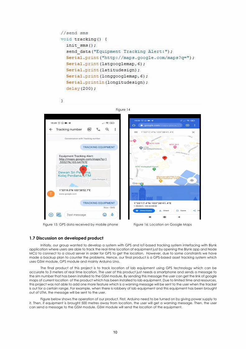
The Arduino is waiting to receive a response while the lab equipment tracking system is in standby mode. If a message is received, which is “Tracking Equipment”, Arduino extracts and processes the corresponding location from the GPS. After that, Arduino will grant the GSM module the command to send messages and links as coded in the software. Users will use the link to link to Google Map and check the tracking system. If a message is not sent, Arduino can continue to loop and wait until a message is received. The fusion of 3 main components made the system fully operational. All use GSM, GPS and Arduino to work from the first stage of initialization to the last step of message sending. The figure below shows the coding of sms that will send the link of google map to the user.
10
Figure 14
Figure 15: GPS data received by mobile phone Figure 16: Location on Google Maps
1.7 Discussion on developed product Initially, our group wanted to develop a system with GPS and IoT-based tracking system interfacing with Blynk
application where users are able to track the real-time location of equipment just by opening the Blynk app and Node MCU to connect to a cloud server in order for GPS to get the location. However, due to some constraints we have made a backup plan to counter the problems. Hence, our final product is a GPS-based asset tracking system which uses GSM module, GPS module and mainly Arduino Uno.
The final product of this project is to track location of lab equipment using GPS technology which can be accurate to 3 meters of real time location. The user of this product just needs a smartphone and sends a message to the sim number that has been installed to the GSM module. By sending this message the user can get the link of google maps of current location of the product which has been installed to lab equipment. Due to limited time and resources, this project was not able to add one more feature which is a warning message will be sent to the user when the tracker is out for a certain range. For example, when there is robbery of lab equipment and this equipment has been brought out of UTM, the message will be sent to the user.
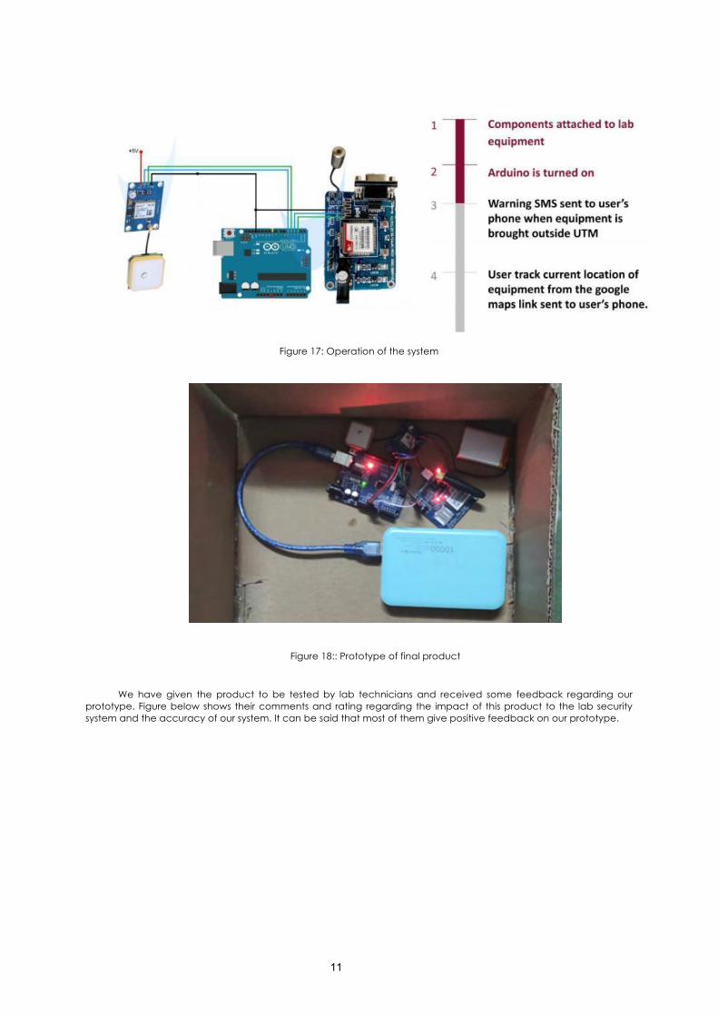
Figure below shows the operation of our product. First, Arduino need to be turned on by giving power supply to it. Then, if equipment is brought 500 metres away from location, the user will get a warning message. Then, the user can send a message to the GSM module. GSM module will send the location of the equipment.
11
Figure 17: Operation of the system
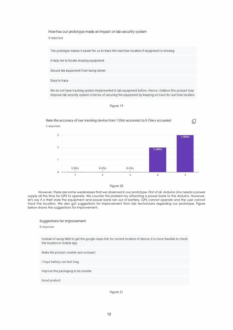
Figure 18:: Prototype of final product
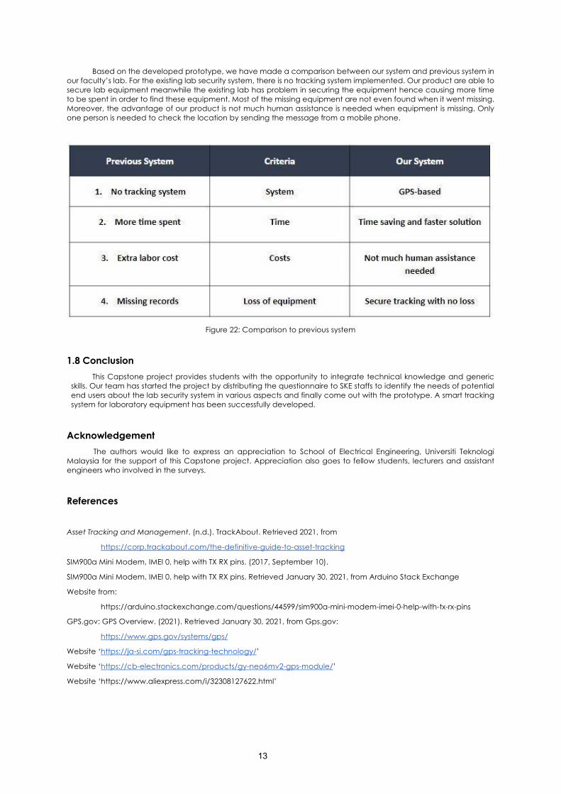
We have given the product to be tested by lab technicians and received some feedback regarding our prototype. Figure below shows their comments and rating regarding the impact of this product to the lab security system and the accuracy of our system. It can be said that most of them give positive feedback on our prototype.
12
Figure 19
Figure 20
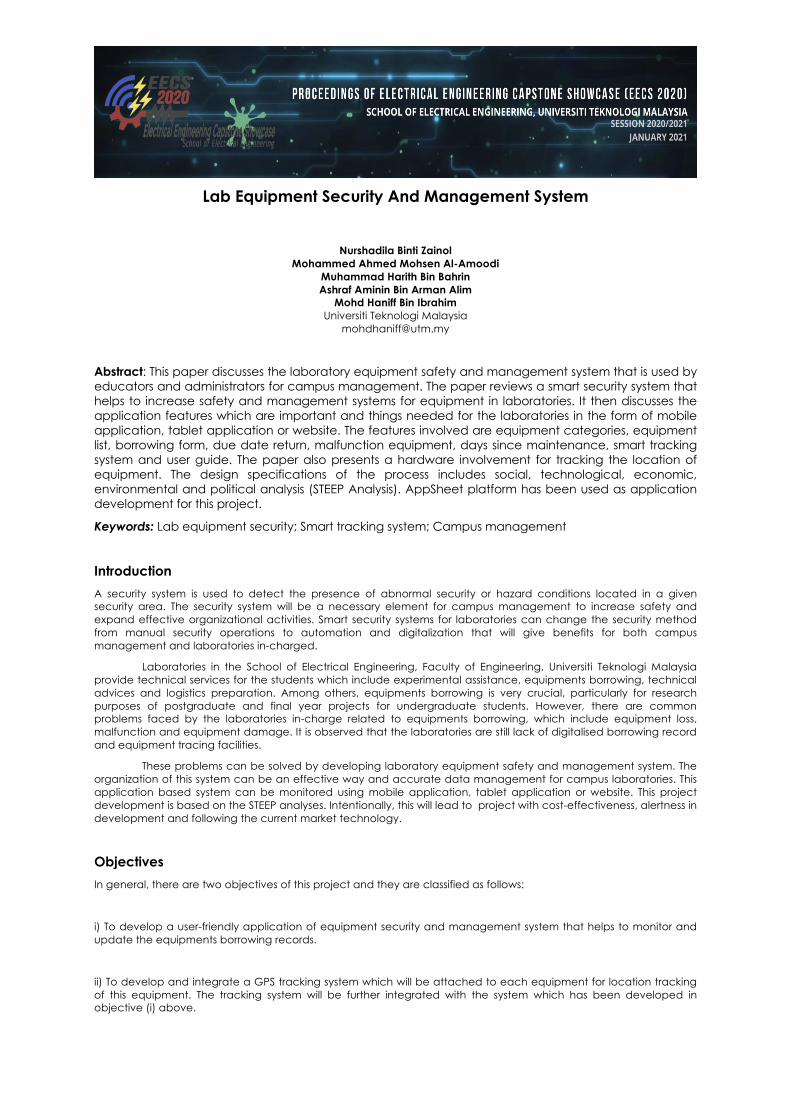
However, there are some weaknesses that we observed in our prototype. First of all, Arduino Uno needs a power supply all the time for GPS to operate. We counter this problem by attaching a power bank to the Arduino. However, let's say if a thief stole the equipment and power bank ran out of battery, GPS cannot operate and the user cannot track the location. We also got suggestions for improvement from lab technicians regarding our prototype. Figure below shows the suggestions for improvement.
Figure 21
13
Based on the developed prototype, we have made a comparison between our system and previous system in our faculty’s lab. For the existing lab security system, there is no tracking system implemented. Our product are able to secure lab equipment meanwhile the existing lab has problem in securing the equipment hence causing more time to be spent in order to find these equipment. Most of the missing equipment are not even found when it went missing. Moreover, the advantage of our product is not much human assistance is needed when equipment is missing. Only one person is needed to check the location by sending the message from a mobile phone.
Figure 22: Comparison to previous system
1.8 Conclusion This Capstone project provides students with the opportunity to integrate technical knowledge and generic
skills. Our team has started the project by distributing the questionnaire to SKE staffs to identify the needs of potential end users about the lab security system in various aspects and finally come out with the prototype. A smart tracking system for laboratory equipment has been successfully developed.
Acknowledgement The authors would like to express an appreciation to School of Electrical Engineering, Universiti Teknologi
Malaysia for the support of this Capstone project. Appreciation also goes to fellow students, lecturers and assistant engineers who involved in the surveys.
References
Asset Tracking and Management. (n.d.). TrackAbout. Retrieved 2021, from
https://corp.trackabout.com/the-definitive-guide-to-asset-tracking
SIM900a Mini Modem, IMEI 0, help with TX RX pins. (2017, September 10).
SIM900a Mini Modem, IMEI 0, help with TX RX pins. Retrieved January 30, 2021, from Arduino Stack Exchange
Website from:
https://arduino.stackexchange.com/questions/44599/sim900a-mini-modem-imei-0-help-with-tx-rx-pins
GPS.gov: GPS Overview. (2021). Retrieved January 30, 2021, from Gps.gov:
https://www.gps.gov/systems/gps/
Website ‘https://ja-si.com/gps-tracking-technology/’
Website ‘https://cb-electronics.com/products/gy-neo6mv2-gps-module/’
Website ‘https://www.aliexpress.com/i/32308127622.html’
Lab Equipment Security And Management System
Nurshadila Binti Zainol Mohammed Ahmed Mohsen Al-Amoodi
Muhammad Harith Bin Bahrin Ashraf Aminin Bin Arman Alim
Mohd Haniff Bin Ibrahim Universiti Teknologi Malaysia
Abstract: This paper discusses the laboratory equipment safety and management system that is used by educators and administrators for campus management. The paper reviews a smart security system that helps to increase safety and management systems for equipment in laboratories. It then discusses the application features which are important and things needed for the laboratories in the form of mobile application, tablet application or website. The features involved are equipment categories, equipment list, borrowing form, due date return, malfunction equipment, days since maintenance, smart tracking system and user guide. The paper also presents a hardware involvement for tracking the location of equipment. The design specifications of the process includes social, technological, economic, environmental and political analysis (STEEP Analysis). AppSheet platform has been used as application development for this project.
Keywords: Lab equipment security; Smart tracking system; Campus management
Introduction A security system is used to detect the presence of abnormal security or hazard conditions located in a given security area. The security system will be a necessary element for campus management to increase safety and expand effective organizational activities. Smart security systems for laboratories can change the security method from manual security operations to automation and digitalization that will give benefits for both campus management and laboratories in-charged.
Laboratories in the School of Electrical Engineering, Faculty of Engineering, Universiti Teknologi Malaysia provide technical services for the students which include experimental assistance, equipments borrowing, technical advices and logistics preparation. Among others, equipments borrowing is very crucial, particularly for research purposes of postgraduate and final year projects for undergraduate students. However, there are common problems faced by the laboratories in-charge related to equipments borrowing, which include equipment loss, malfunction and equipment damage. It is observed that the laboratories are still lack of digitalised borrowing record and equipment tracing facilities.
These problems can be solved by developing laboratory equipment safety and management system. The organization of this system can be an effective way and accurate data management for campus laboratories. This application based system can be monitored using mobile application, tablet application or website. This project development is based on the STEEP analyses. Intentionally, this will lead to project with cost-effectiveness, alertness in development and following the current market technology.
Objectives In general, there are two objectives of this project and they are classified as follows:
i) To develop a user-friendly application of equipment security and management system that helps to monitor and update the equipments borrowing records.
ii) To develop and integrate a GPS tracking system which will be attached to each equipment for location tracking of this equipment. The tracking system will be further integrated with the system which has been developed in objective (i) above.
15
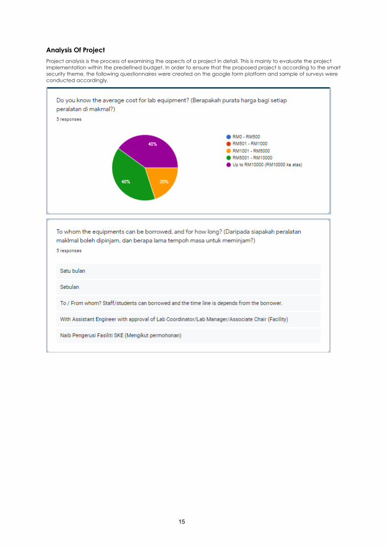
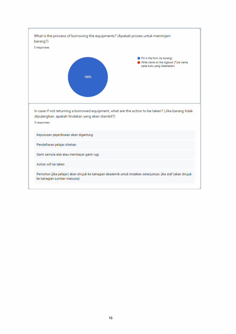
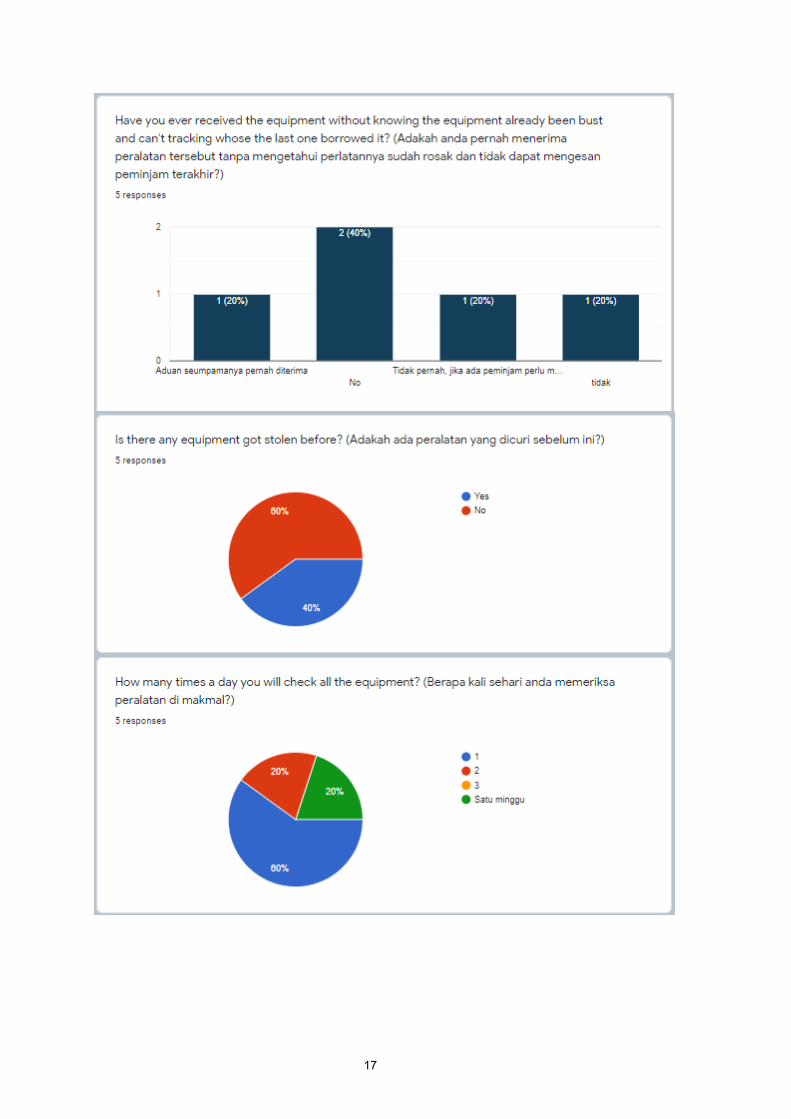
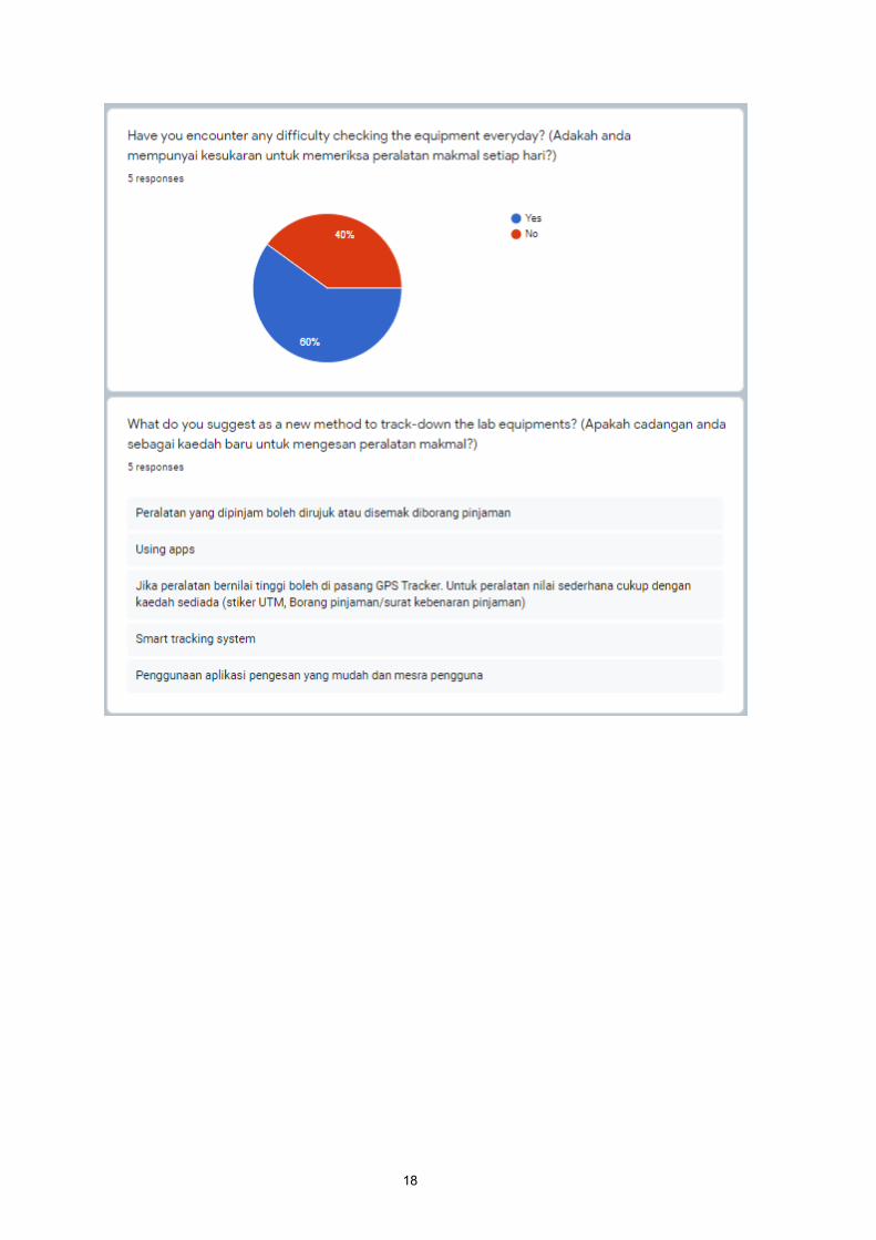
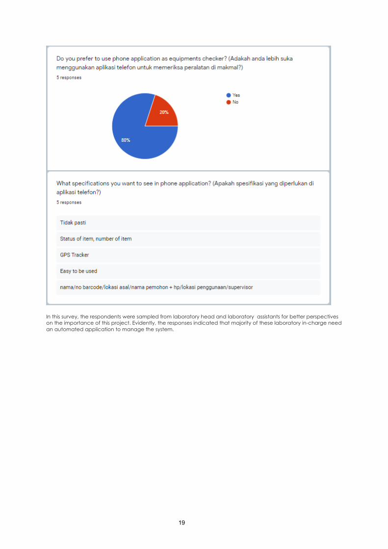
Analysis Of Project Project analysis is the process of examining the aspects of a project in detail. This is mainly to evaluate the project implementation within the predefined budget. In order to ensure that the proposed project is according to the smart security theme, the following questionnaires were created on the google form platform and sample of surveys were conducted accordingly.
16
17
18
19
In this survey, the respondents were sampled from laboratory head and laboratory assistants for better perspectives on the importance of this project. Evidently, the responses indicated that majority of these laboratory in-charge need an automated application to manage the system.
20
Design Statement Design means to create a plan or sketch of something that is going to be made later, especially a plan that details what the final thing will do and look like.
The main objectives of the design for this project is:-
1) To represent all equipment in every laboratory
2) To design an online form of borrowing the equipment
3) To know the In-charge person of borrowing items
4) To track the equipments via the GPS Tracking
5) Create a maintenance scheduling for all item
6) To know the malfunction item in the application
7) To know the status of the equipment borrowed.
8) Create a QR code for every item in the apps to differentiate the same item for each laboratory.
Basically, we create the application features based on the reflections by our respondent and we add extra features based on our discussion with group's supervisor in order to pursue the needs of the respondents.
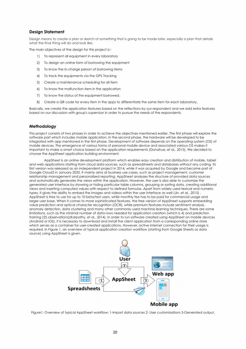
Methodology This project consists of two phases in order to achieve the objectives mentioned earlier. The first phase will explore the software part which includes mobile application. In the second phase, the hardware will be developed to be integrated with app mentioned in the first phase. Development of software depends on the operating system (OS) of mobile devices. The emergence of various forms of personal mobile device and associated various OS makes it important to make a smart choice based on the application requirements (Donahue, et al., 2015). We decided to choose the AppSheet application building environment.
AppSheet is an online development platform which enables easy creation and distribution of mobile, tablet and web applications starting from cloud data sources, such as spreadsheets and databases without any coding. Its first version was released as an independent project in 2014, while it was acquired by Google and became part of Google Cloud2 in January 2020. It mainly aims at business use cases, such as project management, customer relationship management and personalized reporting. AppSheet analyzes the structure of provided data sources and automatically generates the views within the application. However, the user is also able to customize the generated user interface by showing or hiding particular table columns, grouping or sorting data, creating additional views and inserting computed values with respect to defined formulas. Apart from widely used textual and numeric types, it gives the ability to embed the images and videos within the user interface as well (Jin, et al., 2015) . AppSheet is free to use for up to 10 beta/test users, while monthly fee has to be paid for commercial usage and larger user base. When it comes to more sophisticated features, the free version of AppSheet supports embedding value prediction and optical character recognition (OCR), while premium features include sentiment analysis, anomaly detection, data clustering and many other commonly used machine learning techniques. There are some limitations, such as the minimal number of data rows needed for application creation (which is 4) and prediction training (25 observations)(Karpathy, et al., 2014). In order to run software created using AppSheet on mobile devices (Android or iOS), it is necessary to download and install the client application from a corresponding online store which serves as a container for user-created applications. However, active internet connection for their usage is required. In Figure 1, an overview of typical application creation workflow (starting from Google Sheets as data source) using AppSheet is given.
Figure1: Overview of typical AppSheet workflow: 1-Import data sources 2- User customizations 3-Generated output.
21
AppSheet-based mobile applications have been approved as an effective solution across many industrial areas so far. In (Frome, et al., 2013), AppSheet was used for real-time online monitoring of on- shelf availability in case of fast-moving consumer goods (FMCG). On the other side, (Jang, Gu and Pole, 2016), used this app for a water management application that calculates plant water consumption within a given area. When it comes to healthcare, (Li, et al., 2011) leveraged the AppSheet for development of an electronic record keeping system at a pediatric clinic.
In this paper, AppSheet is adopted for our capstone project to help support us with mobile application development, as it enables rapid prototyping and delivery of data-driven mobile applications. As unexpected accidents (such as loss of a lab equipment) might occur suddenly, it is of utmost importance to provide support services and respond to them timely in order to reduce the possible consequences (Hendricks, et al., 2016). Moreover, another advantage of AppSheet is multiplatform support without additional efforts and modifications. Finally, cross platform mobile development frameworks such as Xamarin require solid programming skills, while AppSheet enables easy application creation by domain experts.
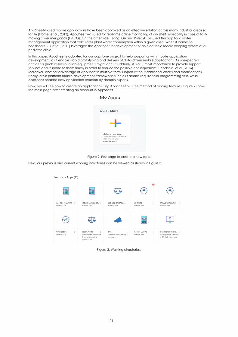
Now, we will see how to create an application using AppSheet plus the method of adding features. Figure 2 shows the main page after creating an account in AppSheet.
Figure 2: First page to create a new app.
Next, our previous and current working directories can be viewed as shown in Figure 3.
Figure 3: Working directories.
22
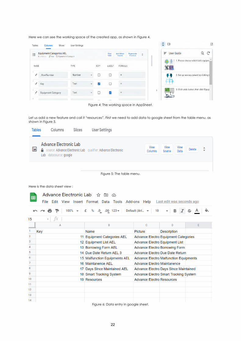
Here we can see the working space of the created app, as shown in Figure 4.
Figure 4: The working space in AppSheet.
Let us add a new feature and call it “resources”. First we need to add data to google sheet from the table menu, as shown in Figure 5.
Figure 5: The table menu.
Here is the data sheet view :
Figure 6: Data entry in google sheet.
23
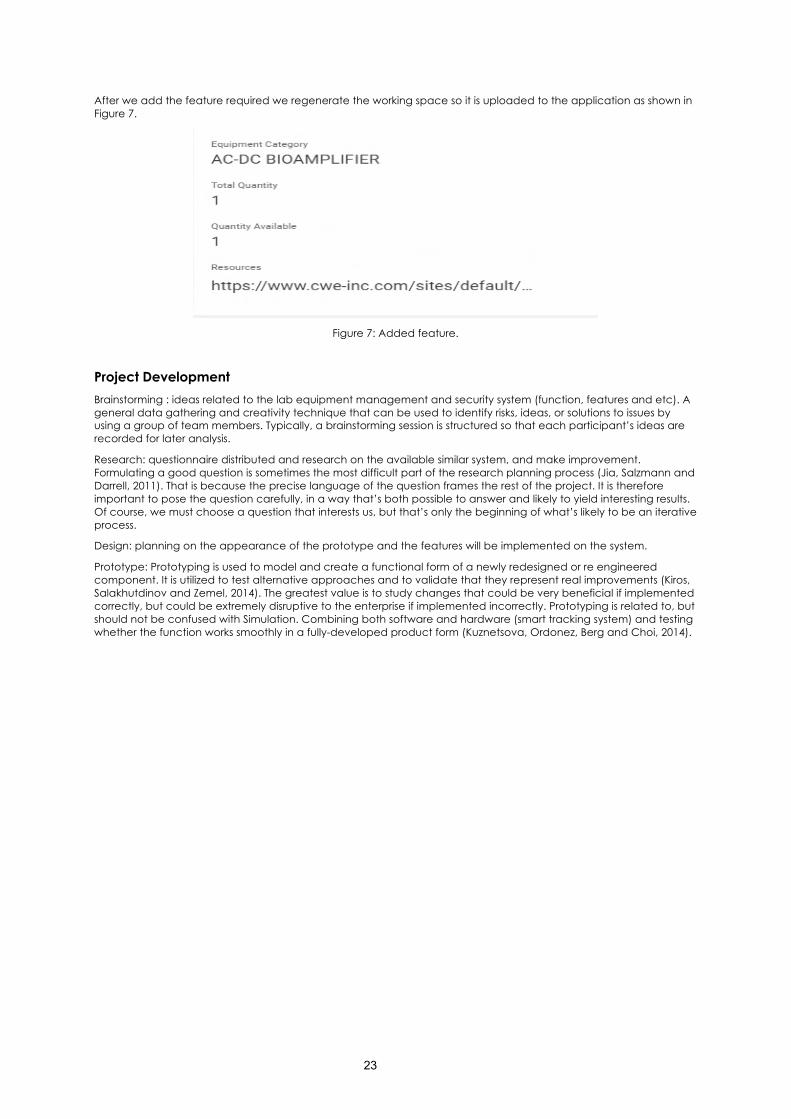
After we add the feature required we regenerate the working space so it is uploaded to the application as shown in Figure 7.
Figure 7: Added feature.
Project Development Brainstorming : ideas related to the lab equipment management and security system (function, features and etc). A general data gathering and creativity technique that can be used to identify risks, ideas, or solutions to issues by using a group of team members. Typically, a brainstorming session is structured so that each participant’s ideas are recorded for later analysis.
Research: questionnaire distributed and research on the available similar system, and make improvement. Formulating a good question is sometimes the most difficult part of the research planning process (Jia, Salzmann and Darrell, 2011). That is because the precise language of the question frames the rest of the project. It is therefore important to pose the question carefully, in a way that’s both possible to answer and likely to yield interesting results. Of course, we must choose a question that interests us, but that’s only the beginning of what’s likely to be an iterative process.
Design: planning on the appearance of the prototype and the features will be implemented on the system.
Prototype: Prototyping is used to model and create a functional form of a newly redesigned or re engineered component. It is utilized to test alternative approaches and to validate that they represent real improvements (Kiros, Salakhutdinov and Zemel, 2014). The greatest value is to study changes that could be very beneficial if implemented correctly, but could be extremely disruptive to the enterprise if implemented incorrectly. Prototyping is related to, but should not be confused with Simulation. Combining both software and hardware (smart tracking system) and testing whether the function works smoothly in a fully-developed product form (Kuznetsova, Ordonez, Berg and Choi, 2014).
24
Discussion
Features and Operations
Lab Equipment Security and Management System comes with many features that are able to track the location of specific equipment for safety purposes. Moreover, it helps the laboratory head and assistant engineer to manage the equipment more efficiently.
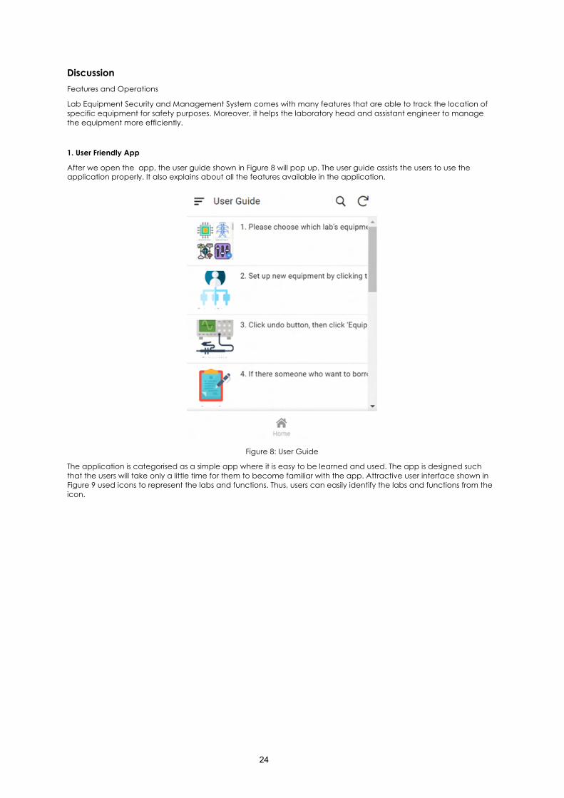
1. User Friendly App
After we open the app, the user guide shown in Figure 8 will pop up. The user guide assists the users to use the application properly. It also explains about all the features available in the application.
Figure 8: User Guide
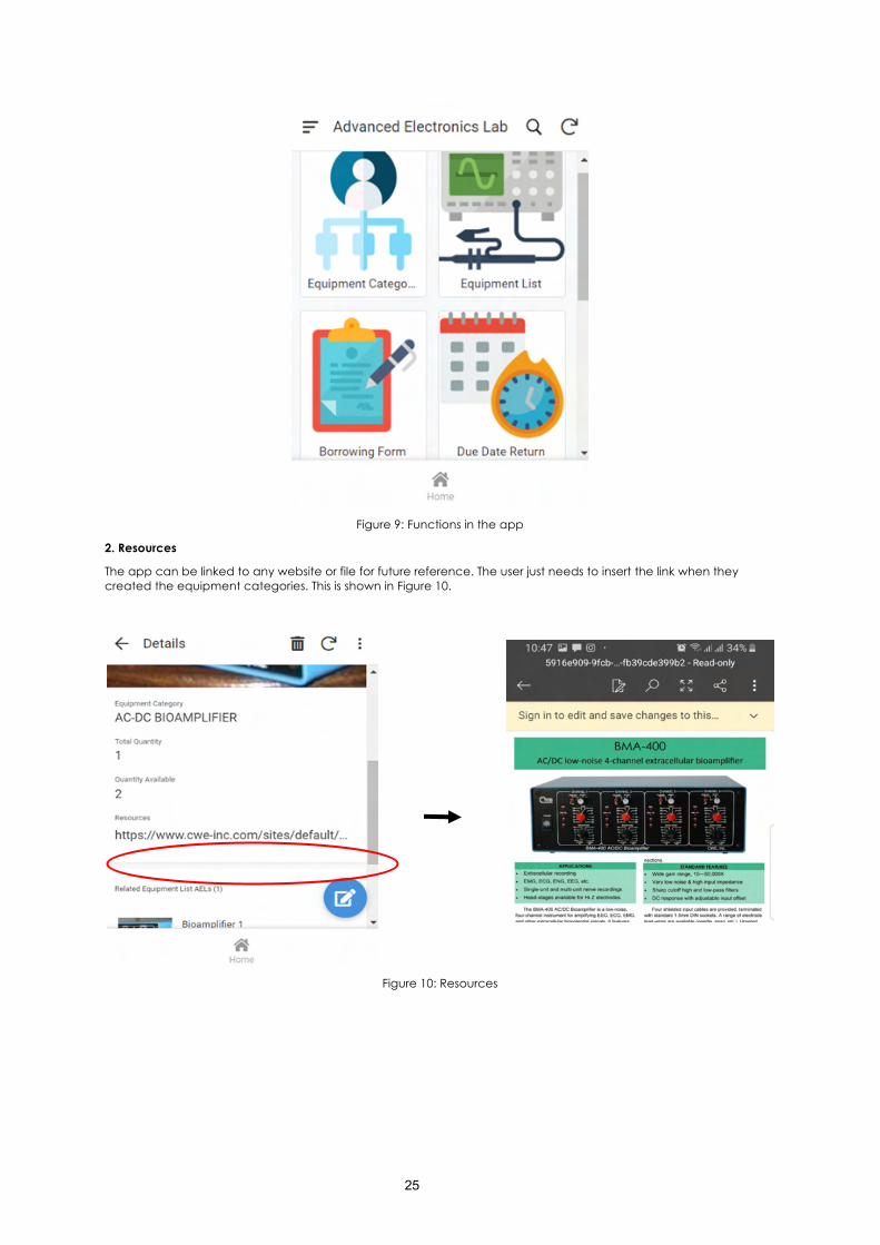
The application is categorised as a simple app where it is easy to be learned and used. The app is designed such that the users will take only a little time for them to become familiar with the app. Attractive user interface shown in Figure 9 used icons to represent the labs and functions. Thus, users can easily identify the labs and functions from the icon.
25
Figure 9: Functions in the app
2. Resources
The app can be linked to any website or file for future reference. The user just needs to insert the link when they created the equipment categories. This is shown in Figure 10.
Figure 10: Resources
26
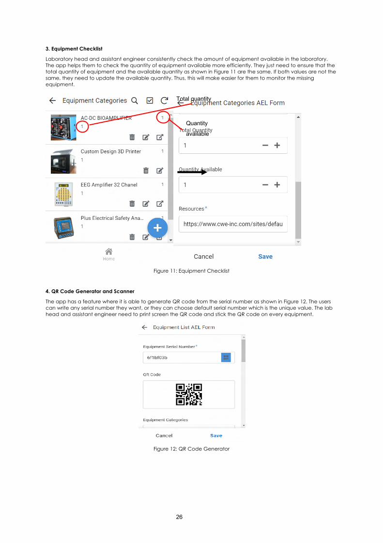
3. Equipment Checklist
Laboratory head and assistant engineer consistently check the amount of equipment available in the laboratory. The app helps them to check the quantity of equipment available more efficiently. They just need to ensure that the total quantity of equipment and the available quantity as shown in Figure 11 are the same. If both values are not the same, they need to update the available quantity. Thus, this will make easier for them to monitor the missing equipment.
Figure 11: Equipment Checklist
4. QR Code Generator and Scanner
The app has a feature where it is able to generate QR code from the serial number as shown in Figure 12. The users can write any serial number they want, or they can choose default serial number which is the unique value. The lab head and assistant engineer need to print screen the QR code and stick the QR code on every equipment.
Figure 12: QR Code Generator
Total quantity
Quantity
available
27
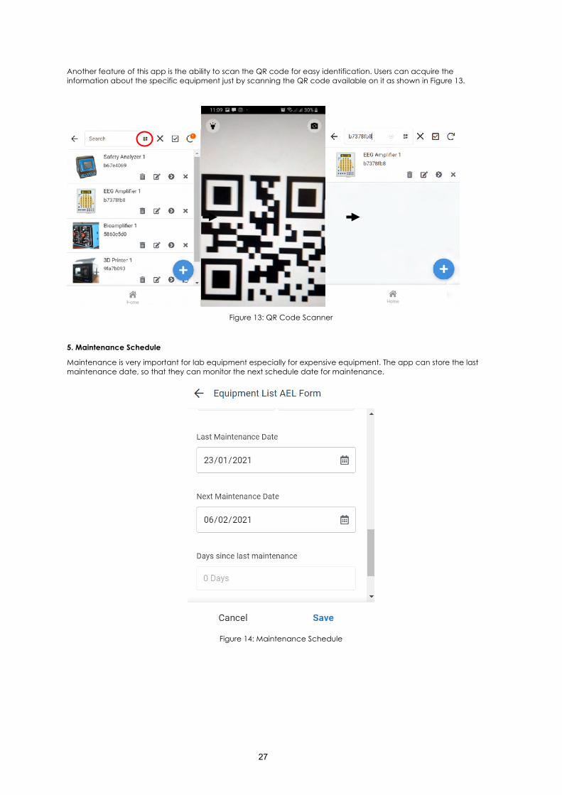
Another feature of this app is the ability to scan the QR code for easy identification. Users can acquire the information about the specific equipment just by scanning the QR code available on it as shown in Figure 13.
Figure 13: QR Code Scanner
5. Maintenance Schedule
Maintenance is very important for lab equipment especially for expensive equipment. The app can store the last maintenance date, so that they can monitor the next schedule date for maintenance.
Figure 14: Maintenance Schedule
28
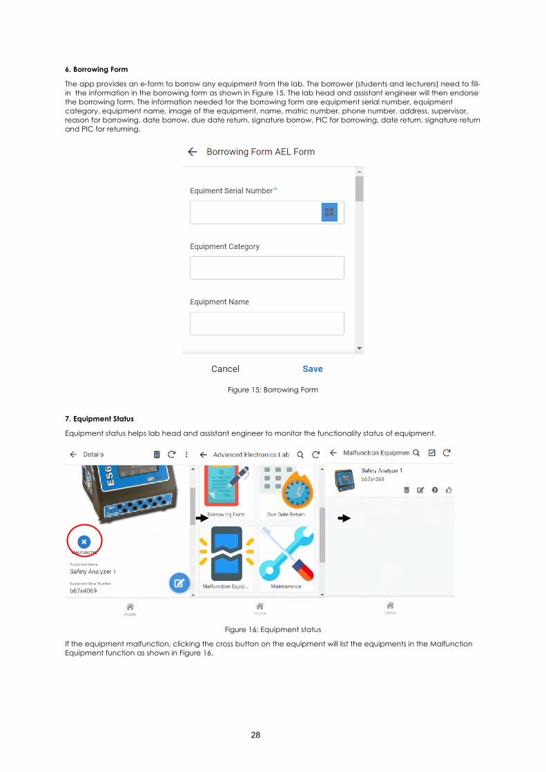
6. Borrowing Form
The app provides an e-form to borrow any equipment from the lab. The borrower (students and lecturers) need to fill-in the information in the borrowing form as shown in Figure 15. The lab head and assistant engineer will then endorse the borrowing form. The information needed for the borrowing form are equipment serial number, equipment category, equipment name, image of the equipment, name, matric number, phone number, address, supervisor, reason for borrowing, date borrow, due date return, signature borrow, PIC for borrowing, date return, signature return and PIC for returning.
Figure 15: Borrowing Form
7. Equipment Status
Equipment status helps lab head and assistant engineer to monitor the functionality status of equipment.
Figure 16: Equipment status
If the equipment malfunction, clicking the cross button on the equipment will list the equipments in the Malfunction Equipment function as shown in Figure 16.
29
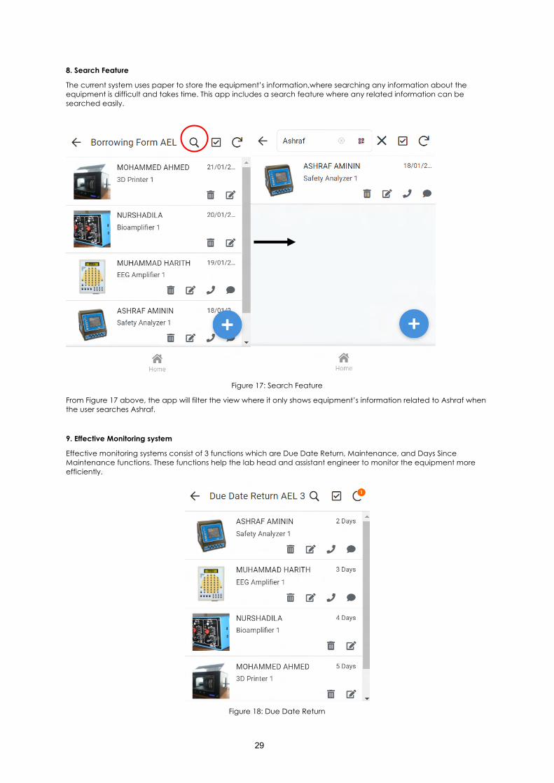
8. Search Feature
The current system uses paper to store the equipment’s information,where searching any information about the equipment is difficult and takes time. This app includes a search feature where any related information can be searched easily.
Figure 17: Search Feature
From Figure 17 above, the app will filter the view where it only shows equipment’s information related to Ashraf when the user searches Ashraf.
9. Effective Monitoring system
Effective monitoring systems consist of 3 functions which are Due Date Return, Maintenance, and Days Since Maintenance functions. These functions help the lab head and assistant engineer to monitor the equipment more efficiently.
Figure 18: Due Date Return
30
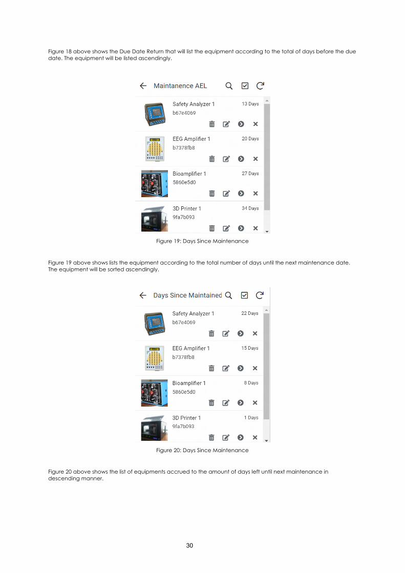
Figure 18 above shows the Due Date Return that will list the equipment according to the total of days before the due date. The equipment will be listed ascendingly.
Figure 19: Days Since Maintenance
Figure 19 above shows lists the equipment according to the total number of days until the next maintenance date. The equipment will be sorted ascendingly.
Figure 20: Days Since Maintenance
Figure 20 above shows the list of equipments accrued to the amount of days left until next maintenance in descending manner.
31
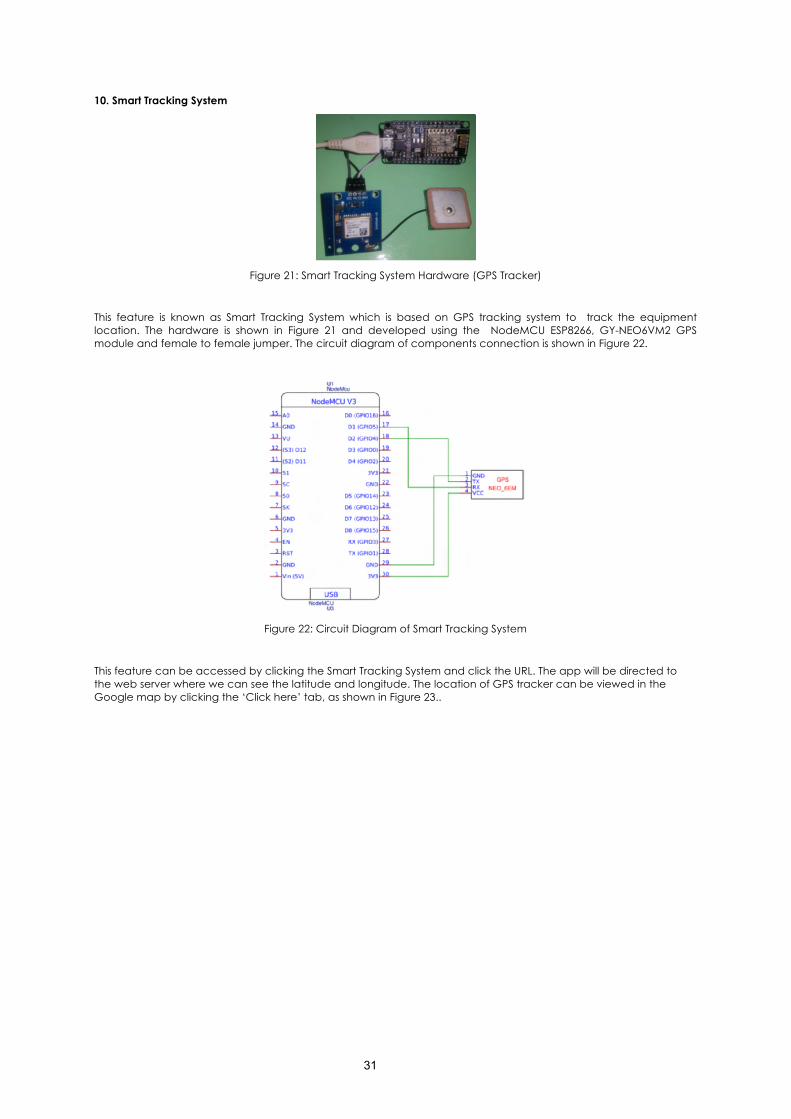
10. Smart Tracking System
Figure 21: Smart Tracking System Hardware (GPS Tracker)
This feature is known as Smart Tracking System which is based on GPS tracking system to track the equipment location. The hardware is shown in Figure 21 and developed using the NodeMCU ESP8266, GY-NEO6VM2 GPS module and female to female jumper. The circuit diagram of components connection is shown in Figure 22.
Figure 22: Circuit Diagram of Smart Tracking System
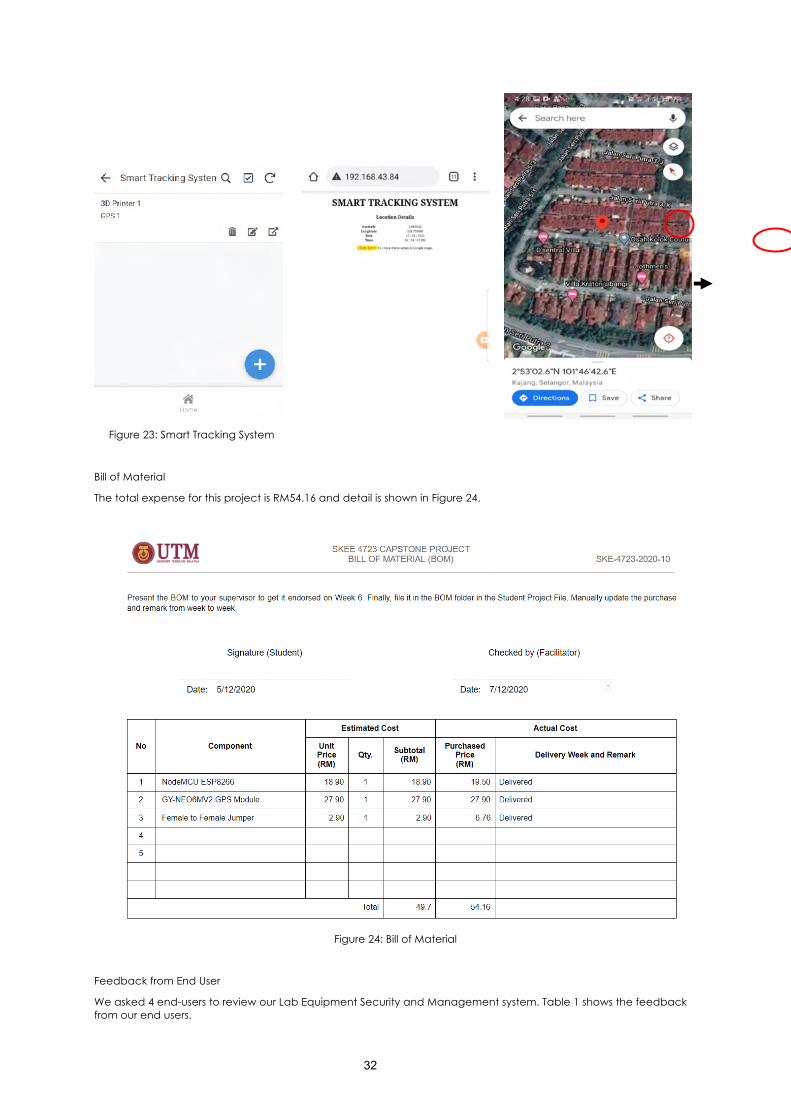
This feature can be accessed by clicking the Smart Tracking System and click the URL. The app will be directed to the web server where we can see the latitude and longitude. The location of GPS tracker can be viewed in the Google map by clicking the ‘Click here’ tab, as shown in Figure 23..
32
Figure 23: Smart Tracking System
Bill of Material
The total expense for this project is RM54.16 and detail is shown in Figure 24.
Figure 24: Bill of Material
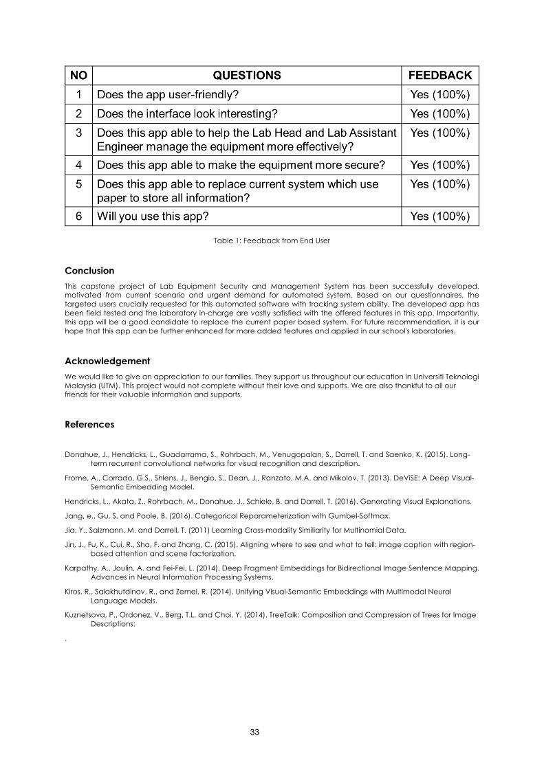
Feedback from End User
We asked 4 end-users to review our Lab Equipment Security and Management system. Table 1 shows the feedback from our end users.
33
Table 1: Feedback from End User
Conclusion This capstone project of Lab Equipment Security and Management System has been successfully developed, motivated from current scenario and urgent demand for automated system. Based on our questionnaires, the targeted users crucially requested for this automated software with tracking system ability. The developed app has been field tested and the laboratory in-charge are vastly satisfied with the offered features in this app. Importantly, this app will be a good candidate to replace the current paper based system. For future recommendation, it is our hope that this app can be further enhanced for more added features and applied in our school's laboratories.
Acknowledgement We would like to give an appreciation to our families. They support us throughout our education in Universiti Teknologi Malaysia (UTM). This project would not complete without their love and supports. We are also thankful to all our friends for their valuable information and supports.
References
Donahue, J., Hendricks, L., Guadarrama, S., Rohrbach, M., Venugopalan, S., Darrell, T. and Saenko, K. (2015). Long-term recurrent convolutional networks for visual recognition and description.
Frome, A., Corrado, G.S., Shlens, J., Bengio, S., Dean, J., Ranzato, M.A. and Mikolov, T. (2013). DeViSE: A Deep Visual-Semantic Embedding Model.
Hendricks, L., Akata, Z., Rohrbach, M., Donahue, J., Schiele, B. and Darrell, T. (2016). Generating Visual Explanations.
Jang, e., Gu, S. and Poole, B. (2016). Categorical Reparameterization with Gumbel-Softmax.
Jia, Y., Salzmann, M. and Darrell, T. (2011) Learning Cross-modality Similiarity for Multinomial Data.
Jin, J., Fu, K., Cui, R., Sha, F. and Zhang, C. (2015). Aligning where to see and what to tell: image caption with region-based attention and scene factorization.
Karpathy, A., Joulin, A. and Fei-Fei, L. (2014). Deep Fragment Embeddings for Bidirectional Image Sentence Mapping. Advances in Neural Information Processing Systems.
Kiros, R., Salakhutdinov, R., and Zemel, R. (2014). Unifying Visual-Semantic Embeddings with Multimodal Neural Language Models.
Kuznetsova, P., Ordonez, V., Berg, T.L. and Choi, Y. (2014). TreeTalk: Composition and Compression of Trees for Image Descriptions:
.
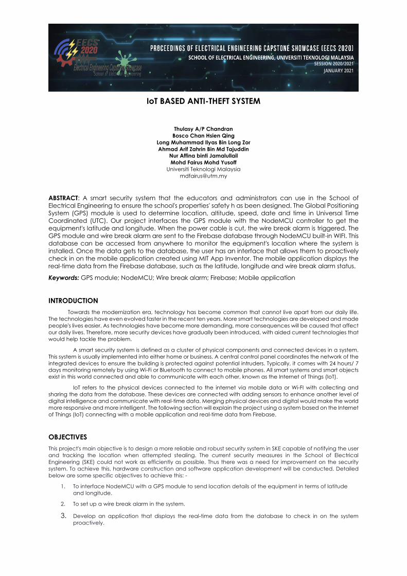
IoT BASED ANTI-THEFT SYSTEM
Thulasy A/P Chandran Bosco Chan Hsien Qing
Long Muhammad Ilyas Bin Long Zor Ahmad Arif Zahrin Bin Md Tajuddin
Nur Affina binti Jamalullail Mohd Fairus Mohd Yusoff
Universiti Teknologi Malaysia [email protected]
ABSTRACT: A smart security system that the educators and administrators can use in the School of Electrical Engineering to ensure the school's properties' safety h as been designed. The Global Positioning System (GPS) module is used to determine location, altitude, speed, date and time in Universal Time Coordinated (UTC). Our project interfaces the GPS module with the NodeMCU controller to get the equipment's latitude and longitude. When the power cable is cut, the wire break alarm is triggered. The GPS module and wire break alarm are sent to the Firebase database through NodeMCU built-in WIFI. This database can be accessed from anywhere to monitor the equipment's location where the system is installed. Once the data gets to the database, the user has an interface that allows them to proactively check in on the mobile application created using MIT App Inventor. The mobile application displays the real-time data from the Firebase database, such as the latitude, longitude and wire break alarm status.
Keywords: GPS module; NodeMCU; Wire break alarm; Firebase; Mobile application
INTRODUCTION Towards the modernization era, technology has become common that cannot live apart from our daily life.
The technologies have even evolved faster in the recent ten years. More smart technologies are developed and made people's lives easier. As technologies have become more demanding, more consequences will be caused that affect our daily lives. Therefore, more security devices have gradually been introduced, with aided current technologies that would help tackle the problem.
A smart security system is defined as a cluster of physical components and connected devices in a system. This system is usually implemented into either home or business. A central control panel coordinates the network of the integrated devices to ensure the building is protected against potential intruders. Typically, it comes with 24 hours/ 7 days monitoring remotely by using Wi-Fi or Bluetooth to connect to mobile phones. All smart systems and smart objects exist in this world connected and able to communicate with each other, known as the Internet of Things (IoT).
IoT refers to the physical devices connected to the internet via mobile data or Wi-FI with collecting and sharing the data from the database. These devices are connected with adding sensors to enhance another level of digital intelligence and communicate with real-time data. Merging physical devices and digital would make the world more responsive and more intelligent. The following section will explain the project using a system based on the Internet of Things (IoT) connecting with a mobile application and real-time data from Firebase.
OBJECTIVES This project's main objective is to design a more reliable and robust security system in SKE capable of notifying the user and tracking the location when attempted stealing. The current security measures in the School of Electrical Engineering (SKE) could not work as efficiently as possible. Thus there was a need for improvement on the security system. To achieve this, hardware construction and software application development will be conducted. Detailed below are some specific objectives to achieve this: -
1. To interface NodeMCU with a GPS module to send location details of the equipment in terms of latitude and longitude.
2. To set up a wire break alarm in the system.
3. Develop an application that displays the real-time data from the database to check in on the system proactively.
35
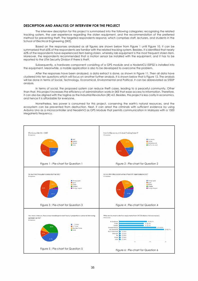
DESCRIPTION AND ANALYSIS OF INTERVIEW FOR THE PROJECT The interview description for this project is summarised into the following categories: recognizing the related
tracking system, the user experience regarding the stolen equipment, and the recommendation of the preferred method for preventing theft. The targeted respondents respond, which comprises staff, lecturers, and students in the School of Electrical Engineering (SKE).
Based on the responses analyzed as all figures are shown below from Figure 1 until Figure 10, it can be summarised that 65% of the respondents are familiar with the related tracking system. Besides, it is identified that nearly 62% of the respondents have experienced item being stolen, whereby lab equipment is the most frequent stolen item. Moreover, the respondents recommended that a motion sensor be installed with the equipment, and it has to be reported to the UTM Security Division if there is theft.
Subsequently, a hardware component consisting of a GPS module and a NodeMCU ESP32 is installed into the equipment. Meanwhile, a mobile application is also to be developed to overcome the problem.
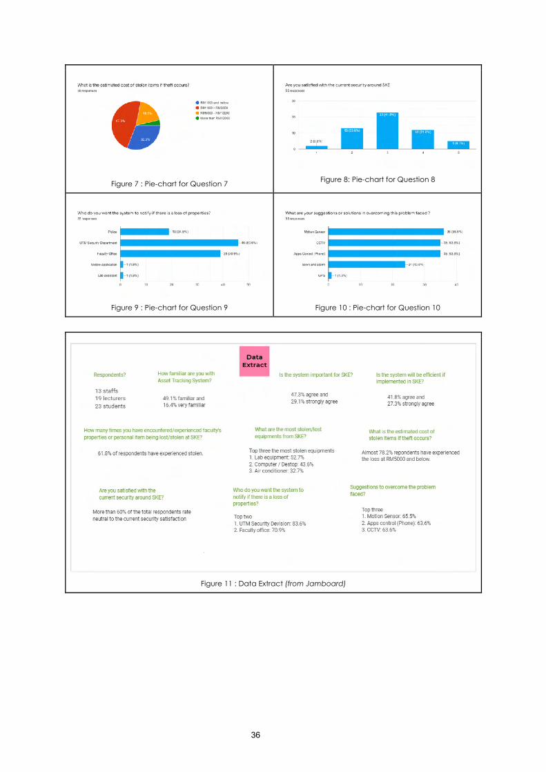
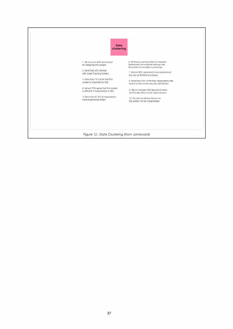
After the responses have been analyzed, a data extract is done, as shown in Figure 11. Then all data have clustered into ten questions which will focus on another further analysis. It is shown below that is Figure 12. The analysis will be done in terms of Social, Technology, Economical, Environmental and Political. It can be abbreviated as STEEP analysis.
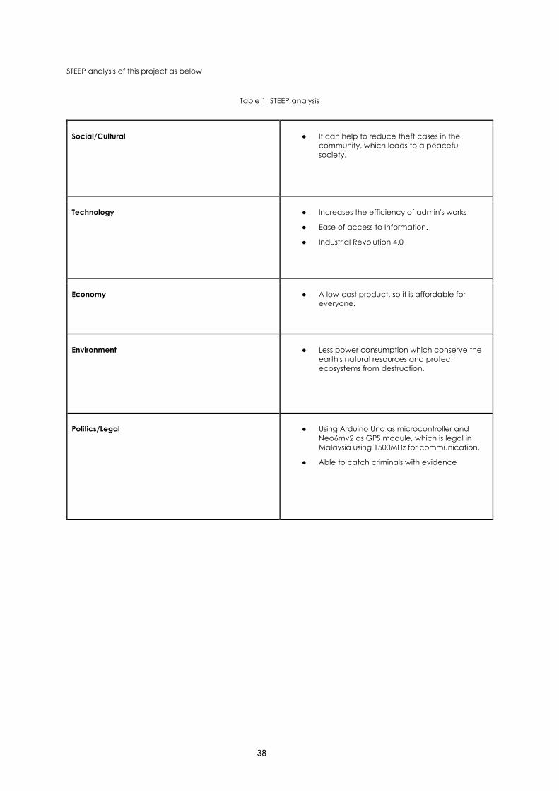
In terms of social, the proposed system can reduce theft cases, leading to a peaceful community. Other than that, this project increases the efficiency of administration works in SKE that ease access to Information. Therefore, it can also be aligned with the tagline as the Industrial Revolution (IR) 4.0. Besides, this project is less costly in economics, and hence it is affordable for everyone.
Nonetheless, less power is consumed for this project, conserving the earth's natural resources, and the ecosystem can be prevented from destruction. Next, it can arrest the criminals with sufficient evidence by using Arduino Uno as a microcontroller and Neo6MV2 as GPS Module that permits communication in Malaysia with a 1500 MegaHertz frequency.
Figure 1 : Pie-chart for Question 1
Figure 2 : Pie-chart for Question 2
Figure 3 : Pie-chart for Question 3
Figure 4 : Pie-chart for Question 4
Figure 5 : Pie-chart for Question 5
Figure 6 : Pie-chart for Question 6
36
Figure 7 : Pie-chart for Question 7
Figure 8: Pie-chart for Question 8
Figure 9 : Pie-chart for Question 9
Figure 10 : Pie-chart for Question 10
Figure 11 : Data Extract (from Jamboard)
37
Figure 12 : Data Clustering (from Jamboard)
38
STEEP analysis of this project as below
Table 1 STEEP analysis
Social/Cultural ● It can help to reduce theft cases in the community, which leads to a peaceful society.
Technology ● Increases the efficiency of admin's works
● Ease of access to Information.
● Industrial Revolution 4.0
Economy ● A low-cost product, so it is affordable for everyone.
Environment ● Less power consumption which conserve the earth's natural resources and protect ecosystems from destruction.
Politics/Legal ● Using Arduino Uno as microcontroller and Neo6mv2 as GPS module, which is legal in Malaysia using 1500MHz for communication.
● Able to catch criminals with evidence
39
DESIGN STATEMENT
Design a more reliable and robust security system that can notify when someone breaks into the school to satisfy his needs. It consists of a prototype that can secure school lab equipment from being stolen by a thief. Significantly, all the items such as air conditioners, projector, computer and printers are costly.
METHODOLOGY
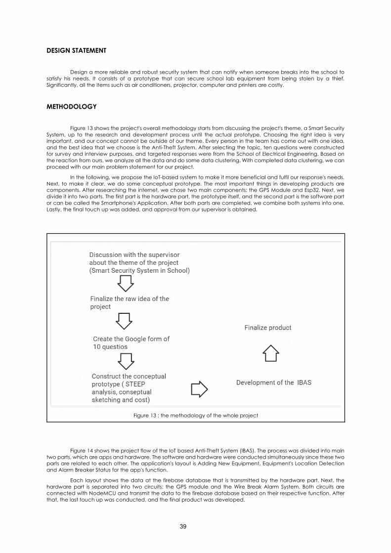
Figure 13 shows the project's overall methodology starts from discussing the project's theme, a Smart Security System, up to the research and development process until the actual prototype. Choosing the right idea is very important, and our concept cannot be outside of our theme. Every person in the team has come out with one idea, and the best idea that we choose is the Anti-Theft System. After selecting the topic, ten questions were constructed for survey and interview purposes, and targeted responses were from the School of Electrical Engineering. Based on the reaction from ours, we analyze all the data and do some data clustering. With completed data clustering, we can proceed with our main problem statement for our project.
In the following, we propose the IoT-based system to make it more beneficial and fulfil our response's needs. Next, to make it clear, we do some conceptual prototype. The most important things in developing products are components. After researching the internet, we chose two main components: the GPS Module and Esp32. Next, we divide it into two parts. The first part is the hardware part, the prototype itself, and the second part is the software part or can be called the Smartphone's Application. After both parts are completed, we combine both systems into one. Lastly, the final touch up was added, and approval from our supervisor is obtained.
Figure 13 : the methodology of the whole project
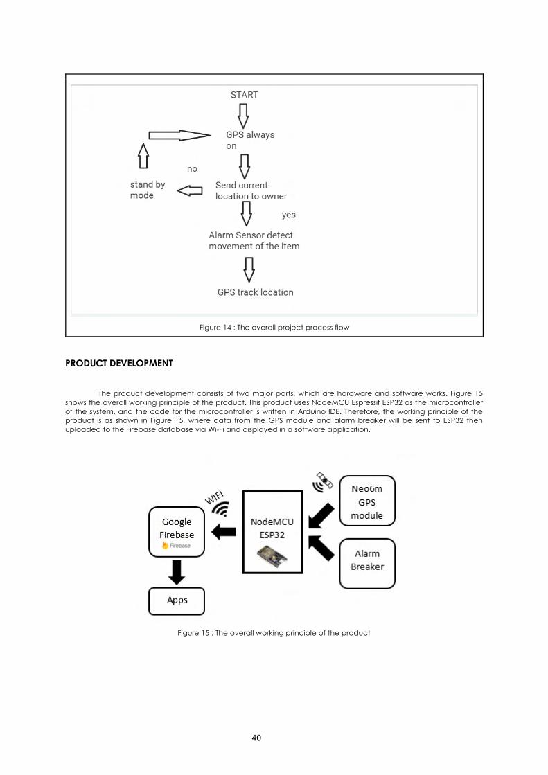
Figure 14 shows the project flow of the IoT based Anti-Theft System (IBAS). The process was divided into main two parts, which are apps and hardware. The software and hardware were conducted simultaneously since these two parts are related to each other. The application's layout is Adding New Equipment, Equipment's Location Detection and Alarm Breaker Status for the app's function.
Each layout shows the data at the firebase database that is transmitted by the hardware part. Next, the hardware part is separated into two circuits: the GPS module and the Wire Break Alarm System. Both circuits are connected with NodeMCU and transmit the data to the firebase database based on their respective function. After that, the last touch up was conducted, and the final product was developed.
40
Figure 14 : The overall project process flow
PRODUCT DEVELOPMENT
The product development consists of two major parts, which are hardware and software works. Figure 15 shows the overall working principle of the product. This product uses NodeMCU Espressif ESP32 as the microcontroller of the system, and the code for the microcontroller is written in Arduino IDE. Therefore, the working principle of the product is as shown in Figure 15, where data from the GPS module and alarm breaker will be sent to ESP32 then uploaded to the Firebase database via Wi-Fi and displayed in a software application.
Figure 15 : The overall working principle of the product
41
HARDWARE DEVELOPMENT The hardware development of this prototype is divided into two parts: hardware for the alarm breaker, while
the second part is hardware for the GPS module.
NodeMCU ESP2
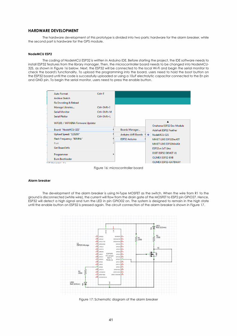
The coding of NodeMCU ESP32 is written in Arduino IDE. Before starting the project, the IDE software needs to install ESP32 features from the library manager. Then, the microcontroller board needs to be changed into NodeMCU-32S, as shown in Figure 16 below. Next, the ESP32 will be connected to the local Wi-Fi and begin the serial monitor to check the board's functionality. To upload the programming into the board, users need to hold the boot button on the ESP32 board until the code is successfully uploaded or using a 10uF electrolytic capacitor connected to the En pin and GND pin. To begin the serial monitor, users need to press the enable button.
Figure 16: microcontroller board
Alarm breaker
The development of the alarm breaker is using N-Type MOSFET as the switch. When the wire from R1 to the ground is disconnected (white wire), the current will flow from the drain gate of the MOSFET to ESP2 pin GPIO27. Hence, ESP32 will detect a high signal and turn the LED in pin GPIO02 on. The system is designed to remain in the high state until the enable button on ESP32 is pressed again. The circuit connection of the alarm breaker is shown in Figure 17.
Figure 17: Schematic diagram of the alarm breaker
42
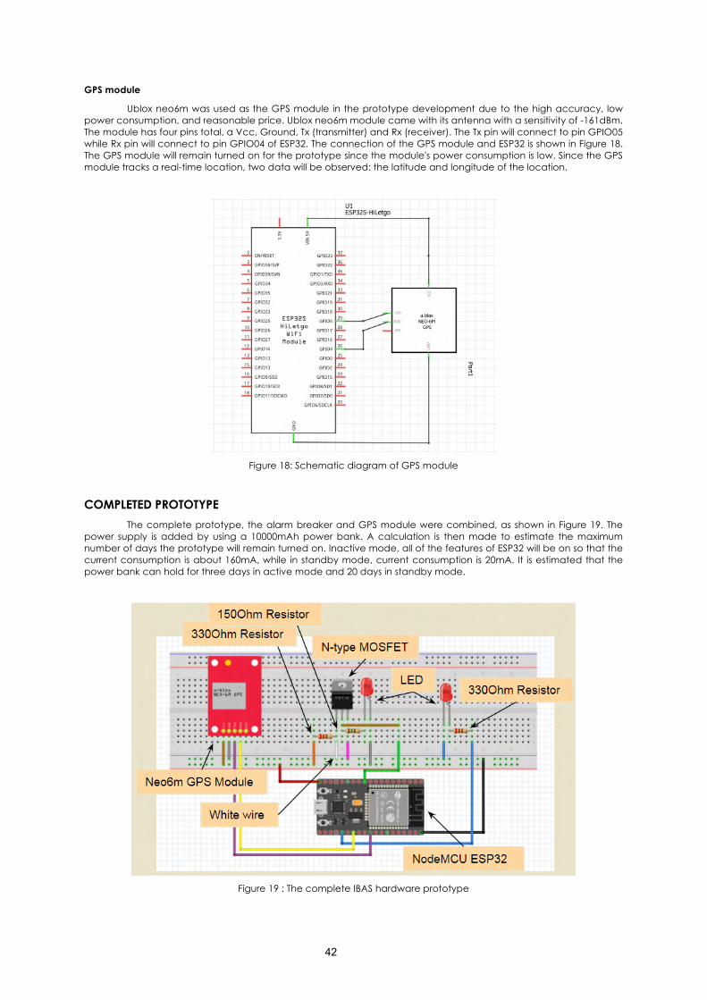
GPS module
Ublox neo6m was used as the GPS module in the prototype development due to the high accuracy, low power consumption, and reasonable price. Ublox neo6m module came with its antenna with a sensitivity of -161dBm. The module has four pins total, a Vcc, Ground, Tx (transmitter) and Rx (receiver). The Tx pin will connect to pin GPIO05 while Rx pin will connect to pin GPIO04 of ESP32. The connection of the GPS module and ESP32 is shown in Figure 18. The GPS module will remain turned on for the prototype since the module's power consumption is low. Since the GPS module tracks a real-time location, two data will be observed: the latitude and longitude of the location.
Figure 18: Schematic diagram of GPS module
COMPLETED PROTOTYPE The complete prototype, the alarm breaker and GPS module were combined, as shown in Figure 19. The
power supply is added by using a 10000mAh power bank. A calculation is then made to estimate the maximum number of days the prototype will remain turned on. Inactive mode, all of the features of ESP32 will be on so that the current consumption is about 160mA, while in standby mode, current consumption is 20mA. It is estimated that the power bank can hold for three days in active mode and 20 days in standby mode.
Figure 19 : The complete IBAS hardware prototype
43
SOFTWARE DEVELOPMENT Software development was divided into two parts: creating a database and the second part is the
development of software application.
Firebase database creation
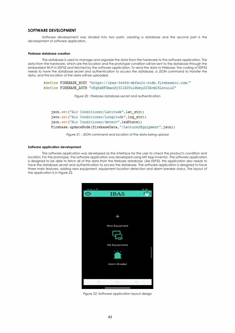
The database is used to manage and organize the data from the hardware to the software application. The data from the hardware, which are the location and the prototype condition will be sent to the database through the embedded Wi-Fi in ESP32 and fetched by the software application. To send the data to Firebase, the coding of ESP32 needs to have the database secret and authentication to access the database, a JSON command to transfer the data, and the location of the data will be uploaded.
Figure 20 : Firebase database secret and authentication
Figure 21 : JSON command and location of the data being upload
Software application development
The software application was developed as the interface for the user to check the product's condition and location. For the prototype, the software application was developed using MIT App Inventor. The software application is designed to be able to fetch all of the data from the firebase database. Like ESP32, this application also needs to have the database secret and authentication to access the database. The software application is designed to have three main features: adding new equipment, equipment location detection and alarm breaker status. The layout of the application is in Figure 22.
Figure 22: Software application layout design
44
DISCUSSION ON DEVELOPED PRODUCT
When the device is in standby mode
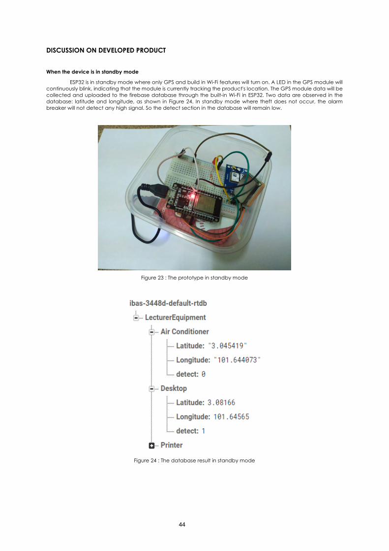
ESP32 is in standby mode where only GPS and build in Wi-Fi features will turn on. A LED in the GPS module will continuously blink, indicating that the module is currently tracking the product's location. The GPS module data will be collected and uploaded to the firebase database through the built-in Wi-Fi in ESP32. Two data are observed in the database: latitude and longitude, as shown in Figure 24. In standby mode where theft does not occur, the alarm breaker will not detect any high signal. So the detect section in the database will remain low.
Figure 23 : The prototype in standby mode
Figure 24 : The database result in standby mode
45
When the device is in the active mode
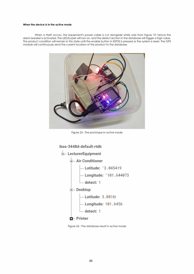
When a theft occurs, the equipment's power cable is cut alongside white wire from Figure 19; hence the alarm breaker is activated. The LED/buzzer will turn on, and the detect section in the database will trigger a high value. The product condition will remain in this state until the enable button in ESP32 is pressed or the system is reset. The GPS module will continuously send the current location of the product to the database.
Figure 25 : The prototype in active mode
Figure 26 : The database result in active mode
46
Software application result
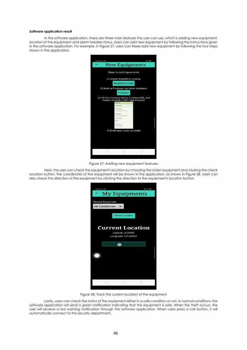
In the software application, there are three main features the user can use, which is adding new equipment, location of the equipment and alarm breaker status. Users can add new equipment by following the instructions given in the software application. For example, in Figure 27, users can freely add new equipment by following the four steps shown in the application.
Figure 27: Adding new equipment features
Next, the user can check the equipment's location by choosing the stolen equipment and clicking the check location button. The coordinates of the equipment will be shown in the application, as shown in Figure 28. Users can also check the direction of the equipment by clicking the direction to the equipment's location button.
Figure 28: Track the current location of the equipment
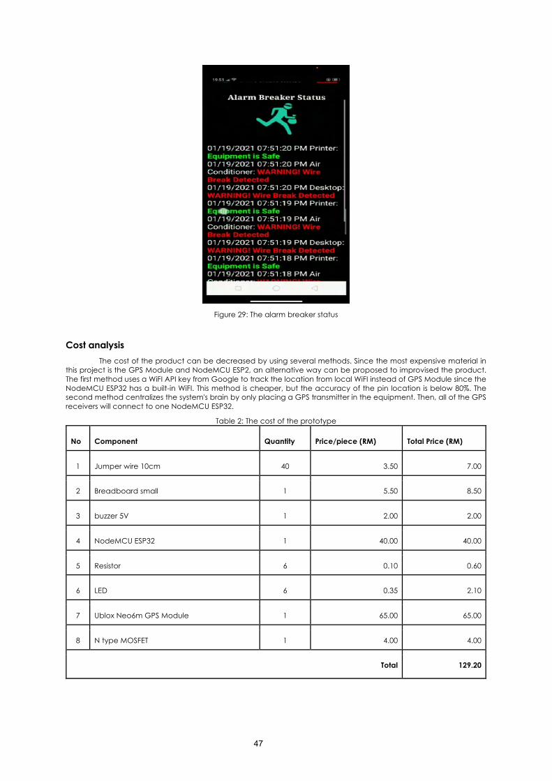
Lastly, users can check the status of the equipment either in a safe condition or not. In normal conditions, the software application will send a green notification indicating that the equipment is safe. When the theft occurs, the user will receive a red warning notification through the software application. When users press a call button, it will automatically connect to the security department.
47
Figure 29: The alarm breaker status
Cost analysis The cost of the product can be decreased by using several methods. Since the most expensive material in
this project is the GPS Module and NodeMCU ESP2, an alternative way can be proposed to improvised the product. The first method uses a WiFI API key from Google to track the location from local WiFI instead of GPS Module since the NodeMCU ESP32 has a built-in WiFI. This method is cheaper, but the accuracy of the pin location is below 80%. The second method centralizes the system's brain by only placing a GPS transmitter in the equipment. Then, all of the GPS receivers will connect to one NodeMCU ESP32.
Table 2: The cost of the prototype
No Component Quantity Price/piece (RM) Total Price (RM)
1 Jumper wire 10cm 40 3.50 7.00
2 Breadboard small 1 5.50 8.50
3 buzzer 5V 1 2.00 2.00
4 NodeMCU ESP32 1 40.00 40.00
5 Resistor 6 0.10 0.60
6 LED 6 0.35 2.10
7 Ublox Neo6m GPS Module 1 65.00 65.00
8 N type MOSFET 1 4.00 4.00
Total 129.20
48
CONCLUSION
To conclude, a smart security system that the educators and administrators can use in the School of Electrical Engineering to ensure the safety of the school's properties has been successfully designed. From tracking the equipment located in latitude and longitude using the GPS module and monitoring the equipment alarm break status using the IBAS application, this smart security system helps increase safety within the campus compound. Overall, the campus communities will see a shift in security methods towards automation and digitalization. Further improvements that may be implemented are to automate calls or messages through IBAS mobile application, install cameras in the security system as a form of secondary CCTV, and PIR sensor to monitor human movement and alarm triggered when removed from the original place.
ACKNOWLEDGEMENT
The project is supported by the School of Electrical Engineering, Universiti Teknologi Teknologi Malaysia. The School of Electrical Engineering has offered this capstone laboratory program to graduate, which can prepare the students with the working environment in the industry for the future. Furthermore, the authors would like to thank the team facilitator, Dr Mohd Fairus Bin Mohd Yusoff, who supervised and oversaw the conduct of the project. Lastly, very thankful to the group members Thulasy A/P Chandran, Bosco Chan Hsien Qing, Long Muhammad Ilyas Bin Long Zor and Ahmad Arif Zahrin Bin Md Tajuddin to complete this project.
49
REFERENCES
[1] Murmu, P. P., Paul, H., Roopa, J. J., & Timothy, A. J. (2019). A Novel modernistic techniques in women security system using ESP32 and Arduino Uno. 2019 2nd International Conference on Signal Processing and Communication (ICSPC). https://doi.org/10.1109/icspc46172.2019.8976745
[2] SafeWise Team. (2020, October 15). What is a Security System and How Does it Work? Retrieved February 9, 2021, from SafeWise website: https://www.safewise.com/home-security-faq/how-do-security-systems-work/
[3] [SOLVED] Failed to connect to ESP32: Timed out waiting for packet header | Random Nerd Tutorials. (2019, February 12). Retrieved February 9, 2021, from Random Nerd Tutorials website: https://randomnerdtutorials.com/solved-failed-to-connect-to-esp32-timed-out-waiting-for-packet-header/
[4] Ranger, S. (2020, February 3). What is the IoT? Everything you need to know about the Internet of Things right now. Retrieved February 9, 2021, from ZDNet website: https://www.zdnet.com/article/what-is-the-internet-of-things-everything-you-need-to-know-about-the-iot-right-now/
[5] Kumar, S. (2018, July 9). GPS Interfacing with NodeMCU: Getting Location Data. Retrieved February 9, 2021, from Circuit Digest website: https://circuitdigest.com/microcontroller-projects/interfacing-gps-with-nodemcu-esp12
[6] Santos, R. (2017, August 29). Decoding and Encoding JSON Arduino | Random Nerd Tutorials. Retrieved February 9, 2021, from Random Nerd Tutorials website: https://randomnerdtutorials.com/decoding-and-encoding-json-with-arduino-or-esp8266/
[7] Welcome to the MIT App Inventor Community. (2020). MIT App Inventor Community. Retrieved February 8, 2021, from MIT App Inventor Community website: https://community.appinventor.mit.edu/
[8] Romin Irani. (2016, September 9). Tutorial : MIT App Inventor + Firebase - Romin Irani's Blog. Retrieved February 8, 2021, from Medium website: https://rominirani.com/tutorial-mit-app-inventor-firebase-4be95051c325?gi=c29ed51443e4
Smart Security Door
Andi Almer Andromeda Rayhan. Tan Zheng Hong
Muhammad Alif bin Mohd Khalil Muhammad Aidil Azroy bin Azman
Siti Zaleha Abdul Hamid Universiti Teknologi Malaysia
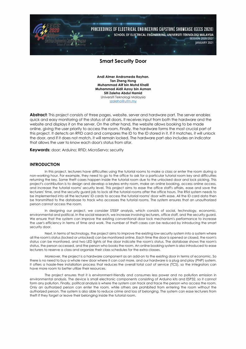
Abstract: This project consists of three pages, website, server and hardware part. The server enables quick and easy monitoring of the status of all doors. It receives input from both the hardware and the website and displays it on the server. On the other hand, the website allows booking to be made online, giving the user priority to access the room. Finally, the hardware forms the most crucial part of this project. It detects an RFID card and compares the ID to the ID stored in it. If it matches, it will unlock the door, and if it does not match, it will remain locked. The hardware part also includes an indicator that allows the user to know each door's status from afar.
Keywords: door; Arduino; RFID; MicroServo; security
INTRODUCTION In this project, lecturers have difficulties using the tutorial rooms to make a class or enter the room during a
non-working hour. For example, they need to go to the office to ask for a particular tutorial room key and difficulties returning the key. Some theft cases happen inside the tutorial room due to the unlocked door and lock picking. This project's contribution is to design and develop a keyless entry room, make an online booking, access online access, and increase the tutorial rooms' security level. This project aims to ease the office staff's affairs, ease and save the lecturers' time, and the security guard job to lock all the tutorial rooms after the office hours. The Rfid system needs to be implemented into all the lecturers' ID cards to access the tutorial rooms' door with ease. All the ID card data then be transmitted to the database to track who accesses the tutorial rooms. The system ensures that an unauthorized person cannot access the room.
In designing our project, we consider STEEP analysis, which consists of social, technology, economic, environmental and political. In the social research, we increase involving lecturers, office staff, and the security guard. We ensure that the system can improve the existing conventional door lock mechanism's performance to increase the user's efficiency in terms of time and work. The number of theft cases can be reduced by introducing the smart security door.
Next, in terms of technology, the project aims to improve the existing low-security system into a system where all the room's status (locked or unlocked) can be monitored online. Each time the door is opened or closed, the room's status can be monitored, and two LED lights at the door indicate the room's status. The database shows the room's status, the person accessed, and the person who books the room. An online booking system is also introduced to ease lecturers to reserve a class and organize their class schedules for the extra classes.
Moreover, the project is a hardware component as an add-on to the existing door in terms of economic. So there is no need to buy a whole new door where it can cost more, and our hardware is a plug and play (PNP) system. It offers a hassle-free installation process that reduces the overall total cost of service (TCS), so the integrators can have more room to better utilize their resources.
The project ensures that it is environment-friendly and consumes less power and no pollution emission in environmental analysis. The device is small electronic components consisting of Arduino kits and ESP32, so it cannot form any pollution. Finally, political analysis is where the system can track and trace the person who access the room. Only an authorized person can enter the room, while others are prohibited from entering the room without the authorized person. The system is also able to reduce crime and loss of belonging. The system can ease lecturers from theft if they forget or leave their belonging inside the tutorial room.
51
CONTENT
1. INNOVATIVE OBJECTIVES 1.1 To allow easy monitoring of all status of classroom. All status of classroom needs to be able to be monitored from afar. An indicator needs to be added to avoid the need to keep track of the status of each classroom manually.
1.2 To allow booking to be made online at all time. Classroom booking should be allowed and whoever made a booking earlier needs to be given priority to access the classroom.
1.3 To allow easy access to the classroom at all time. All users should be allowed to access the classroom in a hassle free way. There will no longer be a need to locate the person in charge.
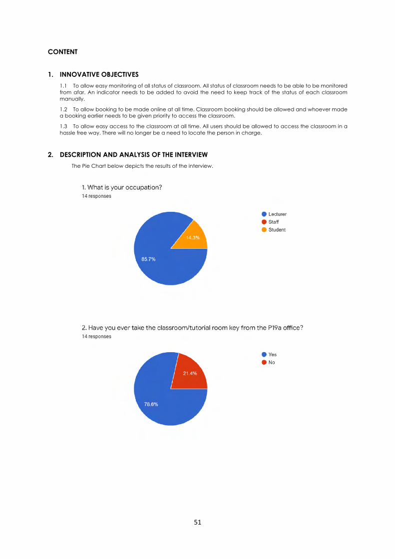
2. DESCRIPTION AND ANALYSIS OF THE INTERVIEW The Pie Chart below depicts the results of the interview.
52
53
54
55
56
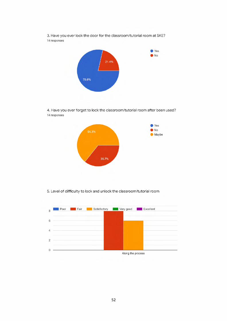
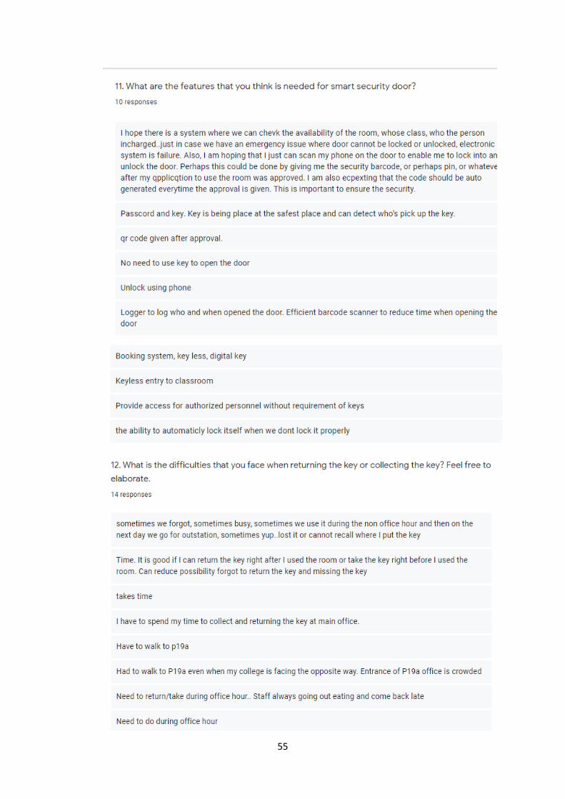
3. Data Analysis We interviewed some of the lecturers to have a better understanding of the users' needs before kickstarting the project. There are altogether 14 respondents that we have interviewed. 85.7% of our respondents are lecturers, and 78.6% of our respondents have experience taking tutorial room keys from the P19 office. However, most of them, which amounts to 78.6%, have never locked the door.
Besides, 64.3% of our respondents have at least once forgotten to lock the classroom door after a lecture. Although most of them think that the current method of accessing the classroom is satisfactorily easy, most of them would like to see improvement in booking the classroom for a lecture at night. This is because it is usually challenging to locate the person in charge to obtain the tutorial room's key. It is even more challenging when you need immediate access to the classroom.
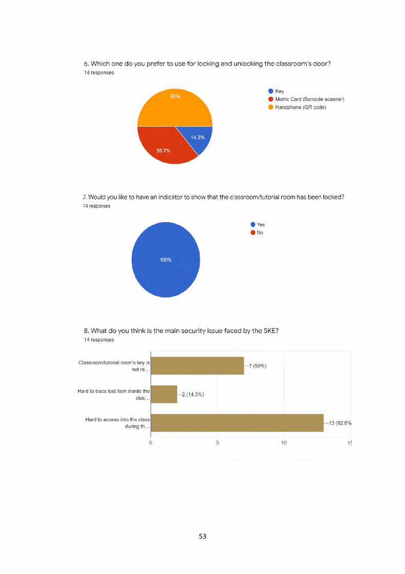
As described by our respondents, many factors contribute to the inconvenience they face daily. As there is currently no systematic method to keep track of who took the keys, sometimes the key is lost, and the faculty will be forced to replace the lock. This again adds to the cost of keeping the faculty safe. It is even more frustrating when you have managed the person in charge after a long search to find out that somebody else has already borrowed the key.
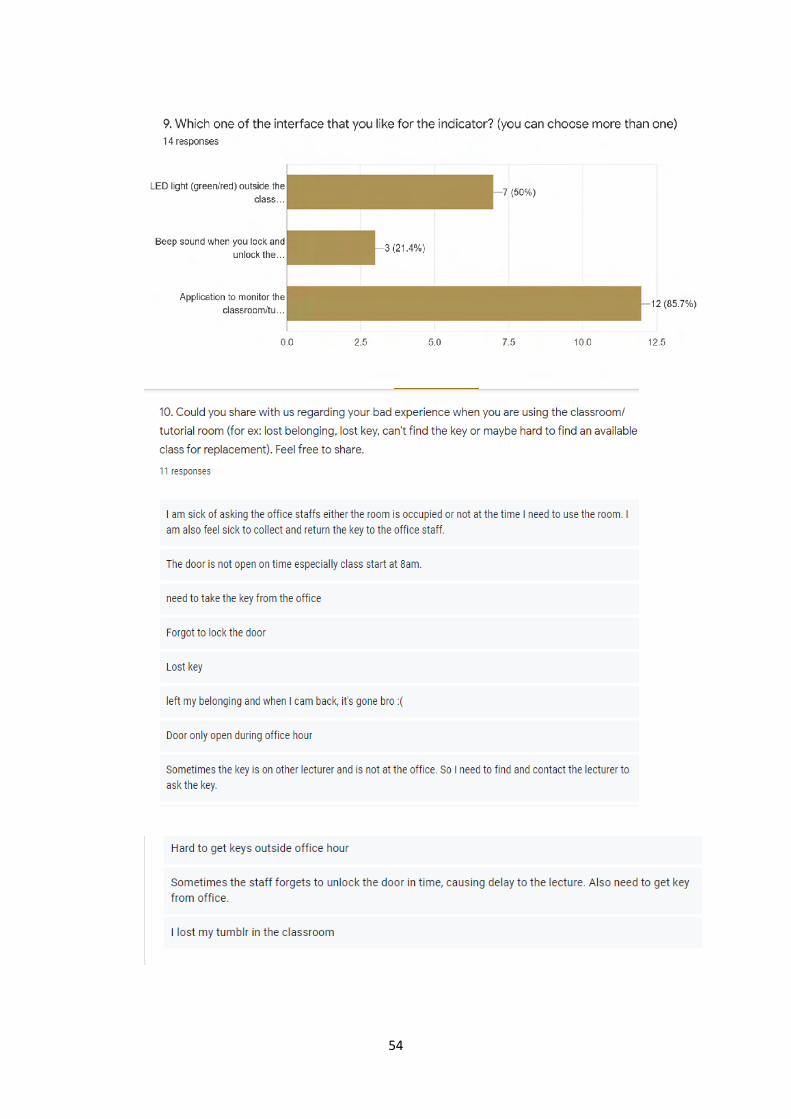
Finally, one of the things that all respondents could agree on was that it would be helpful to have an indicator to indicate the status of each classroom so that there is no need to travel to the classroom to find out that it is already occupied. This will also help our security guard as they now could tell the status of each room at one glance, and there is no longer a need to walk up a building that is 5-storeys high to make sure that the classroom is locked.
4. DESIGN STATEMENT When you want to use a class outside the office hour, it's quite hard to do that in UTM, especially to get the
key and access the office when closed, since UTM still uses a conventional key. So, we try to develop a solution that makes the lecture/student easier when using a class for a replacement class or outside the office hour. By using the Smart door system, the lecturers can easily book the room using a web platform till one hour before they want to use the class, just by choosing what class they want to use, what time, and just press book, then the class can be used in the time that they register.
5. METHODOLOGY
5.1. PROJECT FLOW
In this project, we try our best to overcome the problems that have been arisen. Several issues can be found in the SKE community. This project is focusing on solving security problems.
At the beginning of the project, we make a google to be answered by the SKE community. This google form aims to determine the problem that the SKE community faced. First, the early phase began to discuss and do research on problem-solving. After finding out how to solve the problem, designing our project is the second phase. Then, the hardware and software development and the output be analyzed so that our project can satisfy the problem statement.
57
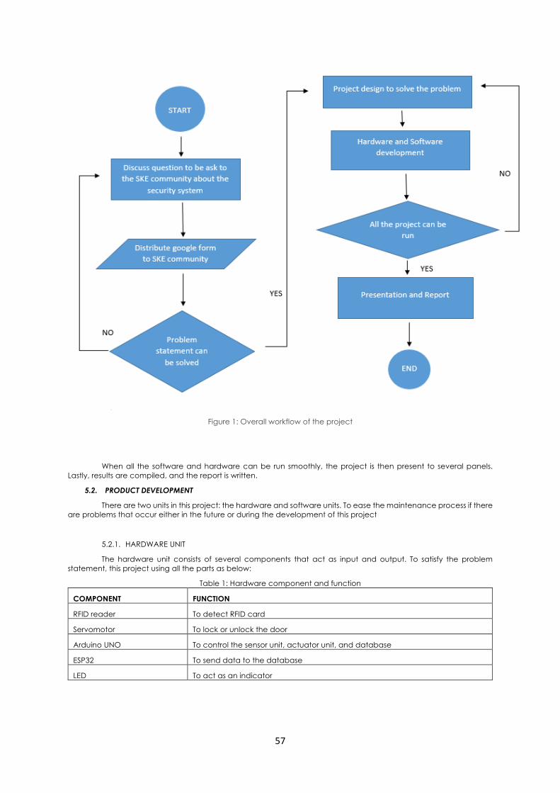
Figure 1: Overall workflow of the project
When all the software and hardware can be run smoothly, the project is then present to several panels. Lastly, results are compiled, and the report is written.
5.2. PRODUCT DEVELOPMENT
There are two units in this project: the hardware and software units. To ease the maintenance process if there are problems that occur either in the future or during the development of this project
5.2.1. HARDWARE UNIT
The hardware unit consists of several components that act as input and output. To satisfy the problem statement, this project using all the parts as below:
Table 1: Hardware component and function
COMPONENT FUNCTION
RFID reader To detect RFID card
Servomotor To lock or unlock the door
Arduino UNO To control the sensor unit, actuator unit, and database
ESP32 To send data to the database
LED To act as an indicator
58
5.2.2. SOFTWARE UNIT
The software unit is consists of Labview and Skeeda, which act as the database, interface, and booking site. The function of the software that is used is:
Table 2: Software and its function
SOFTWARE FUNCTION
LABVIEW To collect data and allow data to be display
SKEEDA For booking site
5.3. SYSTEM DESIGN
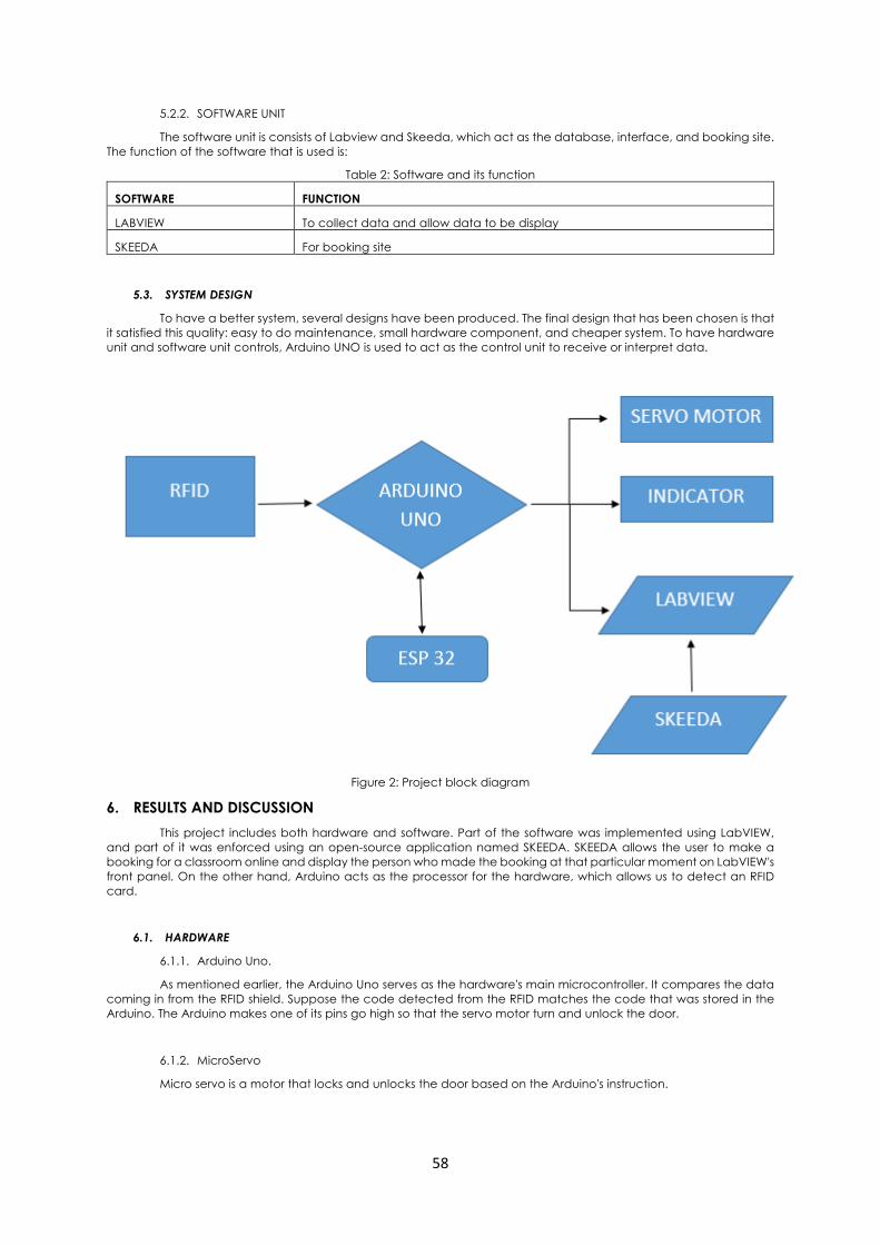
To have a better system, several designs have been produced. The final design that has been chosen is that it satisfied this quality: easy to do maintenance, small hardware component, and cheaper system. To have hardware unit and software unit controls, Arduino UNO is used to act as the control unit to receive or interpret data.
Figure 2: Project block diagram
6. RESULTS AND DISCUSSION This project includes both hardware and software. Part of the software was implemented using LabVIEW,
and part of it was enforced using an open-source application named SKEEDA. SKEEDA allows the user to make a booking for a classroom online and display the person who made the booking at that particular moment on LabVIEW's front panel. On the other hand, Arduino acts as the processor for the hardware, which allows us to detect an RFID card.
6.1. HARDWARE
6.1.1. Arduino Uno.
As mentioned earlier, the Arduino Uno serves as the hardware's main microcontroller. It compares the data coming in from the RFID shield. Suppose the code detected from the RFID matches the code that was stored in the Arduino. The Arduino makes one of its pins go high so that the servo motor turn and unlock the door.
6.1.2. MicroServo
Micro servo is a motor that locks and unlocks the door based on the Arduino's instruction.
59
6.1.3. RC55 RFID
RC55 RFID scans the RFID card and returns the unique code from each RFID to the Arduino so that the Arduino can compare this code to the one stored in Arduino.
6.2. SOFTWARE
6.2.1. LabVIEW
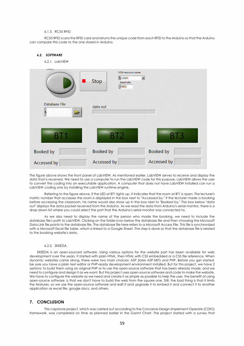
The figure above shows the front panel of LabVIEW. As mentioned earlier, LabVIEW serves to receive and display the data that is received. We need to use a computer to run the LabVIEW code for this purpose. LabVIEW allows the user to convert the coding into an executable application. A computer that does not have LabVIEW installed can run a LabVIEW coding only by installing the LabVIEW runtime engine.
Referring to the figure above, if the LED at BT1 lights up, it indicates that the room at BT1 is open. The lecturer's matric number that accesses the room is displayed in the box next to "Accessed by." If the lecturer made a booking before accessing the classroom, his name would also show up in the box next to "Booked by." The box below "data out" displays the data packet received from the Arduino. As we read the data from Arduino's serial monitor, there is a drop-down list where you could select the port that the Arduino's serial monitor was connected to.
As we also need to display the name of the person who made the booking, we need to include the database file's path to LabVIEW. Clicking on the folder icon below the database file and then choosing the Microsoft Data Link file points to the database file. The database file here refers to a Microsoft Access File. This file is synchronized with a Microsoft Excel file table, which is linked to a Google Sheet. The step is done so that the database file is related to the booking website's data.
6.2.2. SKEEDA.
SKEEDA is an open-sourced software. Using various options for the website part has been available for web development over the years. It started with plain HTML, then HTML with CSS embedded or a CSS file reference. When dynamic websites came along, there were two main choices: ASP (later ASP.NET) and PHP. Before you get started, be sure you have a plain text editor or PHP-ready development environment installed. But for this project, we have 2 options: to build them using an original PHP or to use the open-source software that has been already made, and we need to configure and design it as we want. But this project uses open-source software and code to make the website. We have to configure the website as we need and create it as simple as possible to help the user, the benefit of using open-source software, is that we don't have to build the web from the square one. Still, the bad thing is that it limits the features, so we use the open-source software and edit it and upgrade it to embed it and connect it to another application as excel file, google docs, and others.
7. CONCLUSION This capstone project, which was carried out according to the Conceive-Design-Implement-Operate (CDIO)
framework, was completed on time as planned earlier in the Gannt Chart. The project started with a survey that
Figure SEQ Figure \* ARABIC 3: LabVIEW interface
60
uncovers the lecturer's problem in the School of Electrical Engineering (SKE), Universiti Teknologi Malaysia (UTM). Smart Security Door was implemented successfully, and it functioned according to the design. Each classroom's status can be monitored on the server, and booking can also be made online.
Besides, STEEP Analysis was carried out, and it showed that Smart Security Door would have a substantial impact on society, technology, and the environment.
8. ACKNOWLEDGEMENT
The authors would like to thank all who contributed toward making this research successful. The authors wish to express their gratitude to Ministry of Higher Education (MOHE), Research Management Center (RMC) for the sponsorship, and Telecommunication Software & System (TeSS) Research Group, Universiti Teknologi Malaysia for the financial support and advice for this project. (Vot number Q.J130000.2651.17J70).
9. REFERENCE
Arduino project hub.Retrieved from https://create.arduino.cc/projecthub/projects/tags/lock
Arduino String Tutorial. Retrieved from https://www.arduino.cc/en/Tutorial/BuiltInExamples/#strings
Security Access using MFRC522 RFID Reader with Arduino Retrieved from: https://randomnerdtutorials.com/security-access-using-mfrc522-rfid-reader-with-arduino/
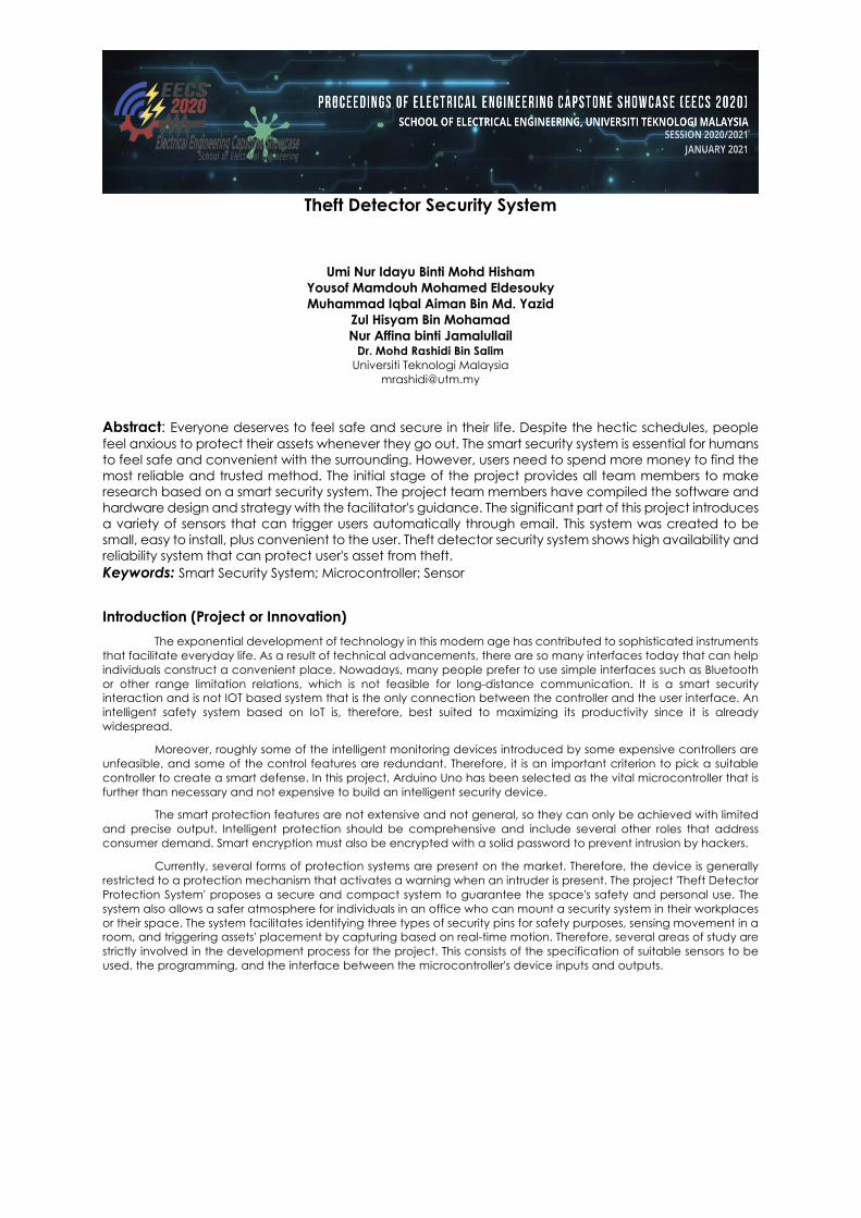
Theft Detector Security System
Umi Nur Idayu Binti Mohd Hisham Yousof Mamdouh Mohamed Eldesouky
Muhammad Iqbal Aiman Bin Md. Yazid
Zul Hisyam Bin Mohamad Nur Affina binti Jamalullail
Dr. Mohd Rashidi Bin Salim Universiti Teknologi Malaysia
Abstract: Everyone deserves to feel safe and secure in their life. Despite the hectic schedules, people feel anxious to protect their assets whenever they go out. The smart security system is essential for humans to feel safe and convenient with the surrounding. However, users need to spend more money to find the most reliable and trusted method. The initial stage of the project provides all team members to make research based on a smart security system. The project team members have compiled the software and hardware design and strategy with the facilitator's guidance. The significant part of this project introduces a variety of sensors that can trigger users automatically through email. This system was created to be small, easy to install, plus convenient to the user. Theft detector security system shows high availability and reliability system that can protect user's asset from theft. Keywords: Smart Security System; Microcontroller; Sensor
Introduction (Project or Innovation)
The exponential development of technology in this modern age has contributed to sophisticated instruments that facilitate everyday life. As a result of technical advancements, there are so many interfaces today that can help individuals construct a convenient place. Nowadays, many people prefer to use simple interfaces such as Bluetooth or other range limitation relations, which is not feasible for long-distance communication. It is a smart security interaction and is not IOT based system that is the only connection between the controller and the user interface. An intelligent safety system based on IoT is, therefore, best suited to maximizing its productivity since it is already widespread.
Moreover, roughly some of the intelligent monitoring devices introduced by some expensive controllers are unfeasible, and some of the control features are redundant. Therefore, it is an important criterion to pick a suitable controller to create a smart defense. In this project, Arduino Uno has been selected as the vital microcontroller that is further than necessary and not expensive to build an intelligent security device.
The smart protection features are not extensive and not general, so they can only be achieved with limited and precise output. Intelligent protection should be comprehensive and include several other roles that address consumer demand. Smart encryption must also be encrypted with a solid password to prevent intrusion by hackers.
Currently, several forms of protection systems are present on the market. Therefore, the device is generally restricted to a protection mechanism that activates a warning when an intruder is present. The project 'Theft Detector Protection System' proposes a secure and compact system to guarantee the space's safety and personal use. The system also allows a safer atmosphere for individuals in an office who can mount a security system in their workplaces or their space. The system facilitates identifying three types of security pins for safety purposes, sensing movement in a room, and triggering assets' placement by capturing based on real-time motion. Therefore, several areas of study are strictly involved in the development process for the project. This consists of the specification of suitable sensors to be used, the programming, and the interface between the microcontroller's device inputs and outputs.
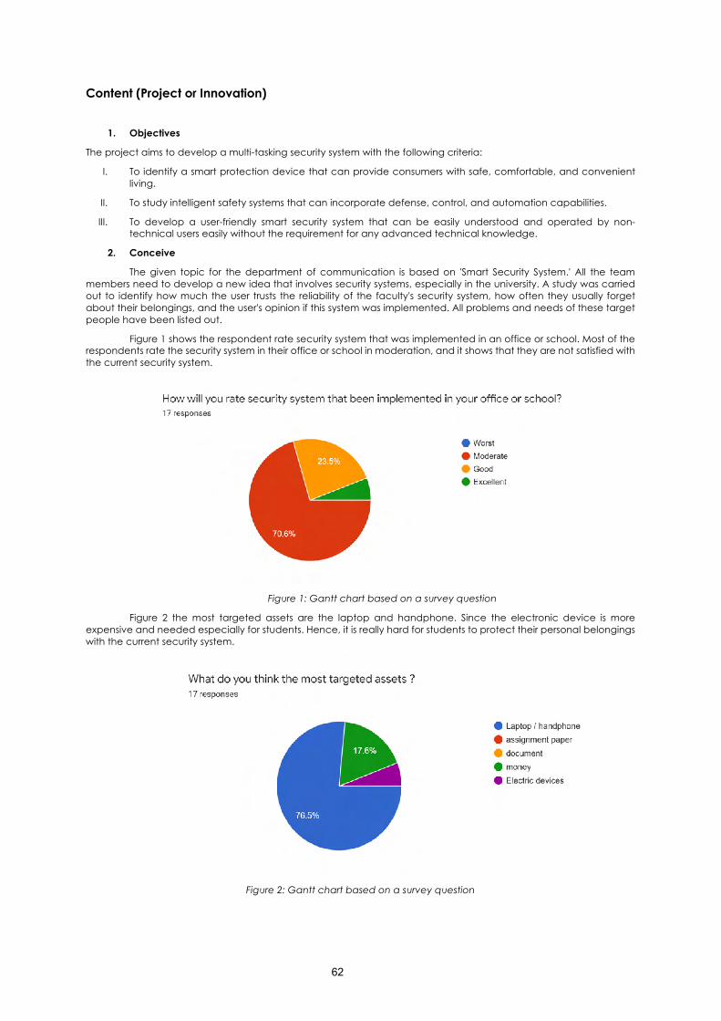
62
Content (Project or Innovation)
1. Objectives
The project aims to develop a multi-tasking security system with the following criteria:
I. To identify a smart protection device that can provide consumers with safe, comfortable, and convenient living.
II. To study intelligent safety systems that can incorporate defense, control, and automation capabilities.
III. To develop a user-friendly smart security system that can be easily understood and operated by non-technical users easily without the requirement for any advanced technical knowledge.
2. Conceive
The given topic for the department of communication is based on 'Smart Security System.' All the team members need to develop a new idea that involves security systems, especially in the university. A study was carried out to identify how much the user trusts the reliability of the faculty's security system, how often they usually forget about their belongings, and the user's opinion if this system was implemented. All problems and needs of these target people have been listed out.
Figure 1 shows the respondent rate security system that was implemented in an office or school. Most of the respondents rate the security system in their office or school in moderation, and it shows that they are not satisfied with the current security system.
Figure 1: Gantt chart based on a survey question
Figure 2 the most targeted assets are the laptop and handphone. Since the electronic device is more expensive and needed especially for students. Hence, it is really hard for students to protect their personal belongings with the current security system.
Figure 2: Gantt chart based on a survey question
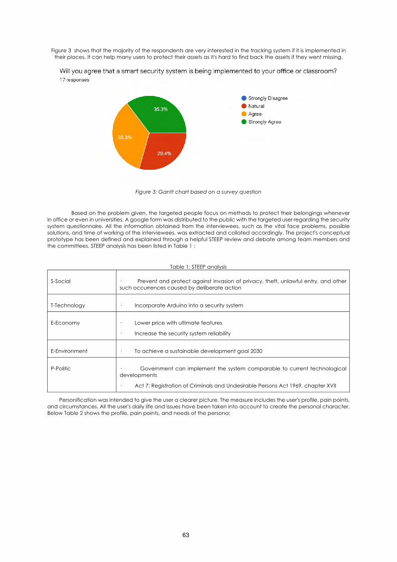
63
Figure 3 shows that the majority of the respondents are very interested in the tracking system if it is implemented in their places. It can help many users to protect their assets as it's hard to find back the assets if they went missing.
Figure 3: Gantt chart based on a survey question
Based on the problem given, the targeted people focus on methods to protect their belongings whenever in office or even in universities. A google form was distributed to the public with the targeted user regarding the security system questionnaire. All the information obtained from the interviewees, such as the vital face problems, possible solutions, and time of working of the interviewees, was extracted and collated accordingly. The project's conceptual prototype has been defined and explained through a helpful STEEP review and debate among team members and the committees. STEEP analysis has been listed in Table 1 :
Table 1: STEEP analysis
S-Social · Prevent and protect against invasion of privacy, theft, unlawful entry, and other such occurrences caused by deliberate action
T-Technology · Incorporate Arduino into a security system
E-Economy · Lower price with ultimate features
· Increase the security system reliability
E-Environment · To achieve a sustainable development goal 2030
P-Politic · Government can implement the system comparable to current technological developments
· Act 7: Registration of Criminals and Undesirable Persons Act 1969, chapter XVII
Personification was intended to give the user a clearer picture. The measure includes the user's profile, pain points, and circumstances. All the user's daily life and issues have been taken into account to create the personal character. Below Table 2 shows the profile, pain points, and needs of the persona:
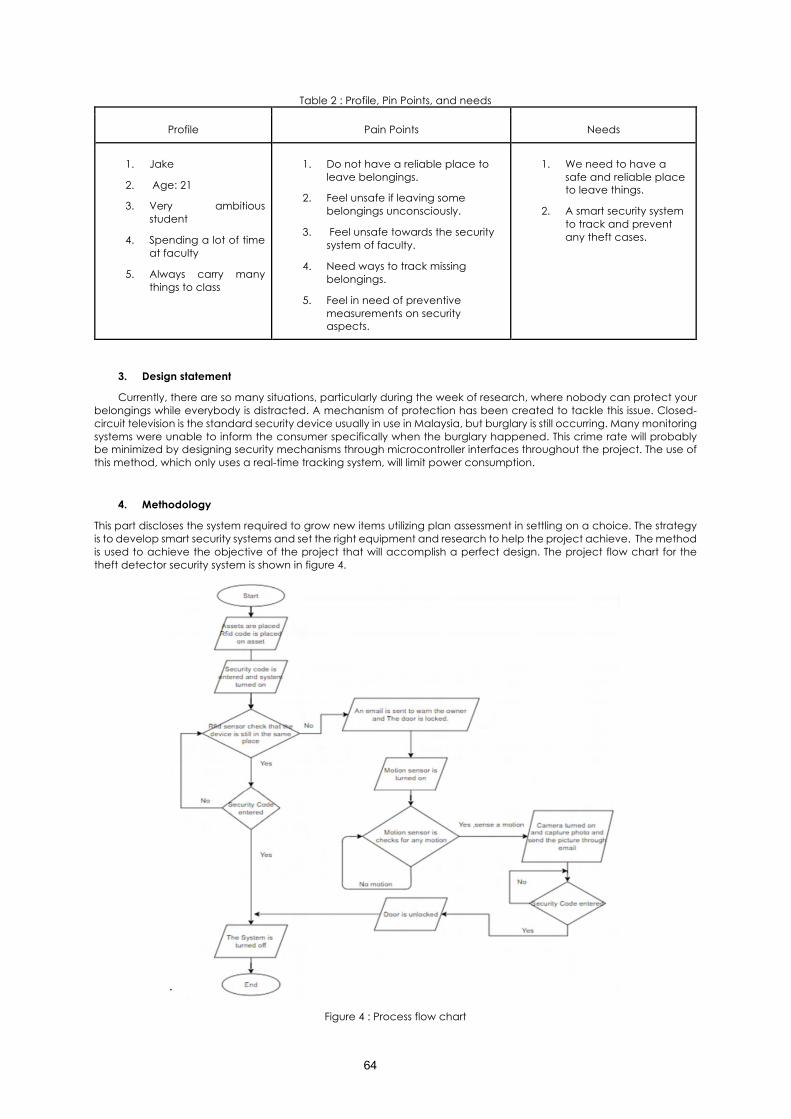
64
Table 2 : Profile, Pin Points, and needs
Profile Pain Points Needs
1. Jake
2. Age: 21
3. Very ambitious student
4. Spending a lot of time at faculty
5. Always carry many things to class
1. Do not have a reliable place to leave belongings.
2. Feel unsafe if leaving some belongings unconsciously.
3. Feel unsafe towards the security system of faculty.
4. Need ways to track missing belongings.
5. Feel in need of preventive measurements on security aspects.
1. We need to have a safe and reliable place to leave things.
2. A smart security system to track and prevent any theft cases.
3. Design statement
Currently, there are so many situations, particularly during the week of research, where nobody can protect your belongings while everybody is distracted. A mechanism of protection has been created to tackle this issue. Closed-circuit television is the standard security device usually in use in Malaysia, but burglary is still occurring. Many monitoring systems were unable to inform the consumer specifically when the burglary happened. This crime rate will probably be minimized by designing security mechanisms through microcontroller interfaces throughout the project. The use of this method, which only uses a real-time tracking system, will limit power consumption.
4. Methodology
This part discloses the system required to grow new items utilizing plan assessment in settling on a choice. The strategy is to develop smart security systems and set the right equipment and research to help the project achieve. The method is used to achieve the objective of the project that will accomplish a perfect design. The project flow chart for the theft detector security system is shown in figure 4.
Figure 4 : Process flow chart
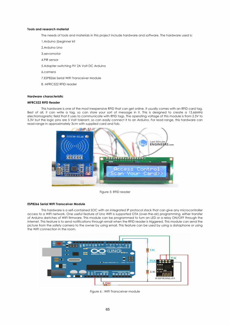
65
Tools and research material
The needs of tools and materials in this project include hardware and software. The hardware used is:
1.Arduino (beginner kit
2.Arduino Uno
3.servomotor
4.PIR sensor
5.Adapter switching 9V 2A Volt DC Arduino
6.camera
7.ESP8266 Serial WIFI Transceiver Module
8. MFRC522 RFID reader
Hardware characteristic
MFRC522 RIFD Reader
This hardware is one of the most inexpensive RFID that can get online. It usually comes with an RFID card tag. Best of all, it can write a tag, so can store your sort of message in it. This is designed to create a 13.66MHz electromagnetic field that it uses to communicate with RFID tags. The operating voltage of this module is from 2.5V to 3.3V but the logic pins are 5 Volt tolerant, so can easily connect it to an Arduino. For read range, this hardware can read range in approximately 3cm with supplied card and fob.
Figure 5: RFID reader
ESP8266 Serial WIFI Transceiver Module
This hardware is a self-contained SOC with an integrated IP protocol stack that can give any microcontroller access to a WIFI network. One useful feature of Uno WIFI is supported OTA (over-the-air) programming, either transfer of Arduino sketches of WIFI firmware. This module can be programmed to turn an LED or a relay ON/OFF through the internet. This feature is to send notifications through email when the RFID reader is triggered. This module can send the picture from the safety camera to the owner by using email. This feature can be used by using a dataphone or using the WIFI connection in the room.
Figure 6 : WIFI Transceiver module
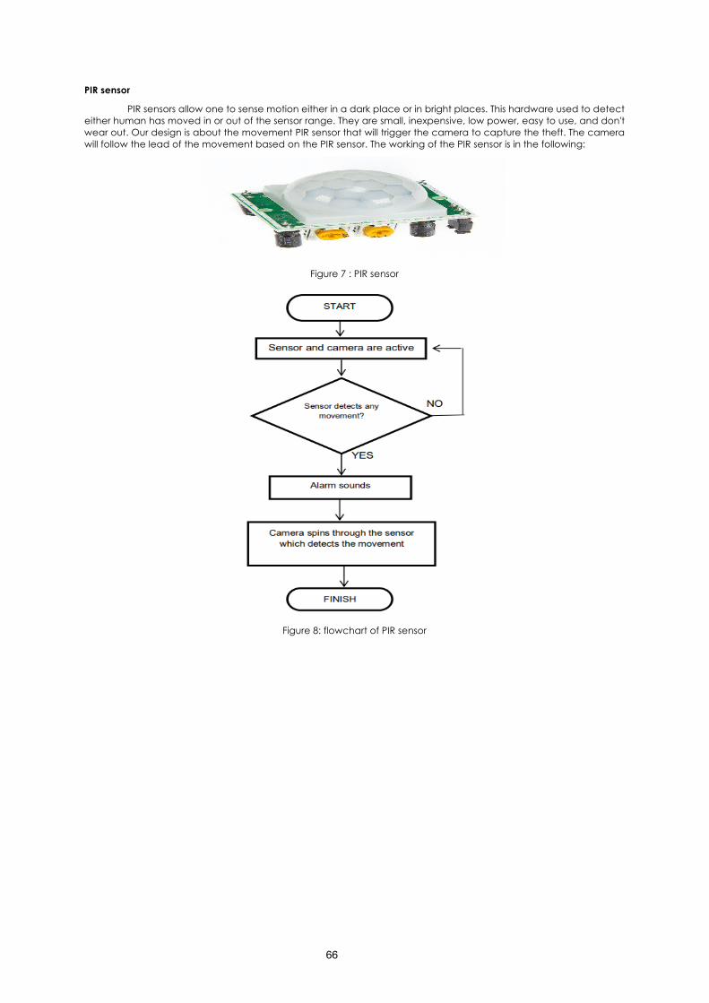
66
PIR sensor
PIR sensors allow one to sense motion either in a dark place or in bright places. This hardware used to detect either human has moved in or out of the sensor range. They are small, inexpensive, low power, easy to use, and don't wear out. Our design is about the movement PIR sensor that will trigger the camera to capture the theft. The camera will follow the lead of the movement based on the PIR sensor. The working of the PIR sensor is in the following:
Figure 7 : PIR sensor
Figure 8: flowchart of PIR sensor
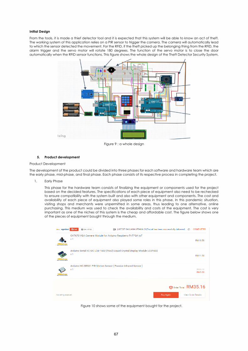
67
Initial Design
From the tools, it is made a thief detector tool and it is expected that this system will be able to know an act of theft. The working system of this application relies on a PIR sensor to trigger the camera. The camera will automatically lead to which the sensor detected the movement. For the RFID, if the theft picked up the belonging thing from the RFID, the alarm trigger and the servo motor will rotate 180 degrees. The function of the servo motor is to close the door automatically when the RFID sensor functions. This figure shows the whole design of the Theft Detector Security System.
Figure 9 : a whole design
5. Product development
Product Development
The development of the product could be divided into three phases for each software and hardware team which are the early phase, mid-phase, and final phase. Each phase consists of its respective process in completing the project.
1. Early Phase
This phase for the hardware team consists of finalizing the equipment or components used for the project based on the decided features. The specifications of each piece of equipment also need to be rechecked to ensure compatibility with the system built and also with other equipment and components. The cost and availability of each piece of equipment also played some roles in this phase. In this pandemic situation, visiting shops and merchants were unpermitted in some areas, thus leading to one alternative, online purchasing. This medium was used to check the availability and costs of the equipment. The cost is very important as one of the niches of this system is the cheap and affordable cost. The figure below shows one of the pieces of equipment bought through the medium.
Figure 10 shows some of the equipment bought for the project.
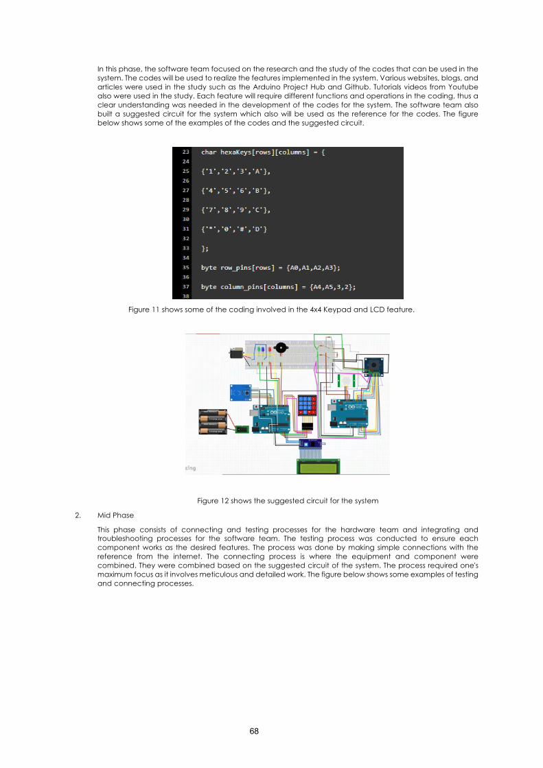
68
In this phase, the software team focused on the research and the study of the codes that can be used in the system. The codes will be used to realize the features implemented in the system. Various websites, blogs, and articles were used in the study such as the Arduino Project Hub and Github. Tutorials videos from Youtube also were used in the study. Each feature will require different functions and operations in the coding, thus a clear understanding was needed in the development of the codes for the system. The software team also built a suggested circuit for the system which also will be used as the reference for the codes. The figure below shows some of the examples of the codes and the suggested circuit.
Figure 11 shows some of the coding involved in the 4x4 Keypad and LCD feature.
Figure 12 shows the suggested circuit for the system
2. Mid Phase
This phase consists of connecting and testing processes for the hardware team and integrating and troubleshooting processes for the software team. The testing process was conducted to ensure each component works as the desired features. The process was done by making simple connections with the reference from the internet. The connecting process is where the equipment and component were combined. They were combined based on the suggested circuit of the system. The process required one's maximum focus as it involves meticulous and detailed work. The figure below shows some examples of testing and connecting processes.
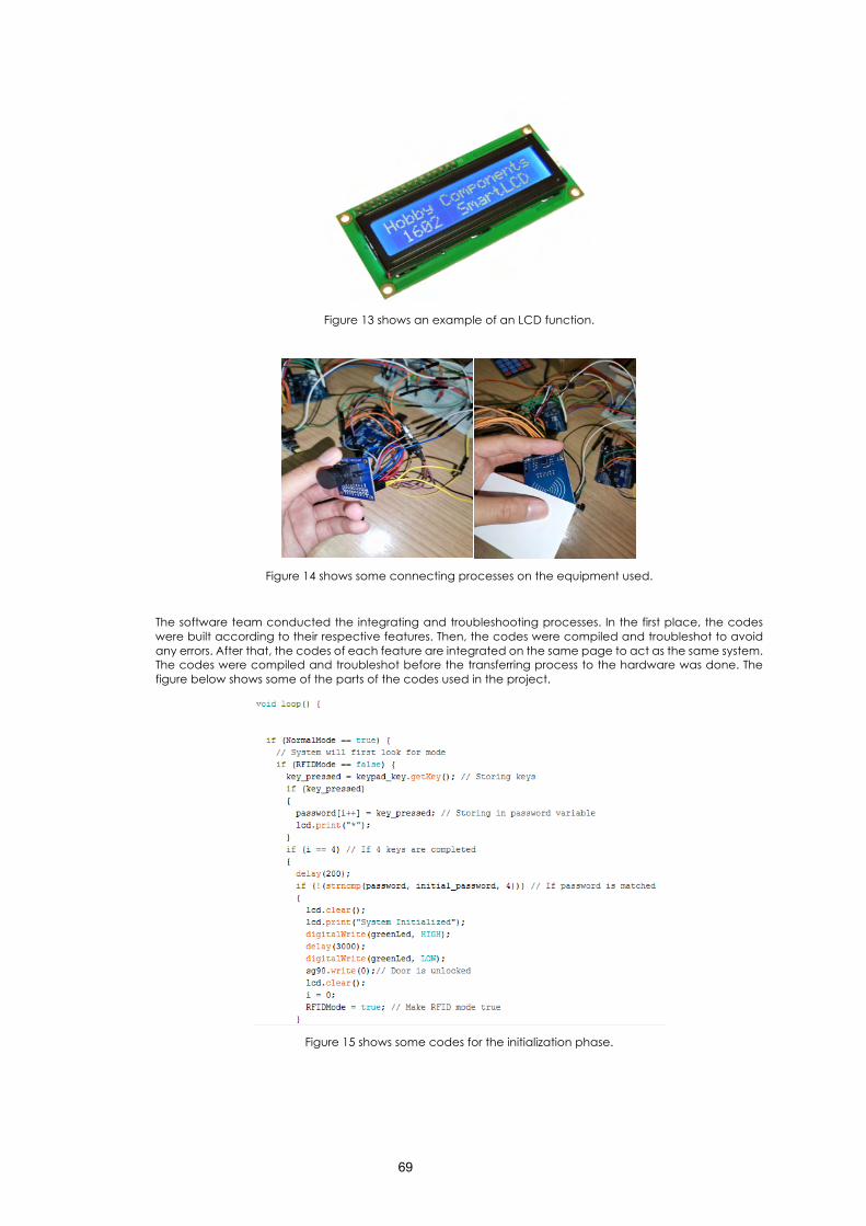
69
Figure 13 shows an example of an LCD function.
Figure 14 shows some connecting processes on the equipment used.
The software team conducted the integrating and troubleshooting processes. In the first place, the codes were built according to their respective features. Then, the codes were compiled and troubleshot to avoid any errors. After that, the codes of each feature are integrated on the same page to act as the same system. The codes were compiled and troubleshot before the transferring process to the hardware was done. The figure below shows some of the parts of the codes used in the project.
Figure 15 shows some codes for the initialization phase.
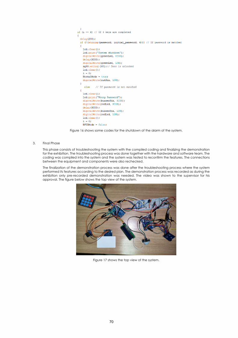
70
Figure 16 shows some codes for the shutdown of the alarm of the system.
3. Final Phase
This phase consists of troubleshooting the system with the compiled coding and finalizing the demonstration for the exhibition. The troubleshooting process was done together with the hardware and software team. The coding was compiled into the system and the system was tested to reconfirm the features. The connections between the equipment and components were also rechecked.
The finalization of the demonstration process was done after the troubleshooting process where the system performed its features according to the desired plan. The demonstration process was recorded as during the exhibition only pre-recorded demonstration was needed. The video was shown to the supervisor for his approval. The figure below shows the top view of the system.
Figure 17 shows the top view of the system.
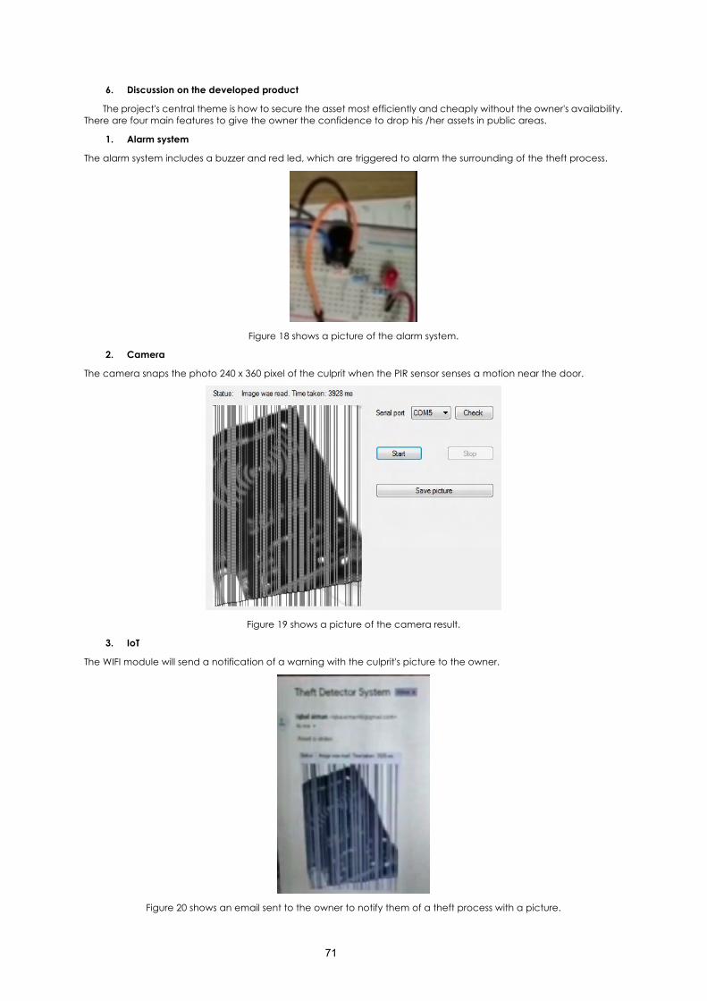
71
6. Discussion on the developed product
The project's central theme is how to secure the asset most efficiently and cheaply without the owner's availability. There are four main features to give the owner the confidence to drop his /her assets in public areas.
1. Alarm system
The alarm system includes a buzzer and red led, which are triggered to alarm the surrounding of the theft process.
Figure 18 shows a picture of the alarm system.
2. Camera
The camera snaps the photo 240 x 360 pixel of the culprit when the PIR sensor senses a motion near the door.
Figure 19 shows a picture of the camera result.
3. IoT
The WIFI module will send a notification of a warning with the culprit's picture to the owner.
Figure 20 shows an email sent to the owner to notify them of a theft process with a picture.
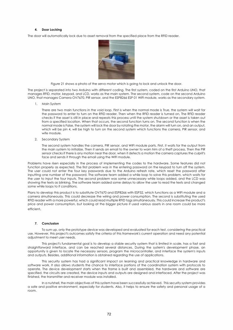
72
4. Door Locking
The door will automatically lock due to asset removal from the specified place from the RFID reader.
Figure 21 shows a photo of the servo motor which is going to lock and unlock the door.
The project is separated into two Arduino with different coding. The first system, coded on the first Arduino UNO, that manages RFID, motor, keypad, and LCD, works as the main system. The second system, code on the second Arduino UNO, that manages Camera OV7670, PIR sensor, and the ESP8266 ESP 01 WIFI module, works as the secondary system.
1. Main System
There are two main functions in the void loop. First is when the normal mode is True, the system will wait for the password to enter to turn on the RFID reader. Then when the RFID reader is turned on, The RFID reader checks if the asset is still in place and repeats this process until the system shutdown or the asset is taken out from a specified location. When that occurs, the second function turns on. The second function is when the normal mode is False, the system will lock the door by rotating the motor, the alarm will turn on, and an output, which will be pin 4, will be high to turn on the second system which functions the camera, PIR sensor, and wife module.
2. Secondary System
The second system handles the camera, PIR sensor, and WIFI module parts. First, it waits for the output from the main system to initialize. Then it sends an email to the owner to warn him of a theft process. Then the PIR sensor checks if there is any motion near the door, when it detects a motion the camera captures the culprit's face and sends it through the email using the WIFI module.
Problems have risen especially in the process of implementing the codes to the hardware. Some features did not function properly as expected. The first problem was in the entering password on the keypad to turn off the system. The user could not enter the four key passwords due to the Arduino refresh rate, which reset the password after inputting one number of the password. The software team added a while loop to solve this problem, which waits for the user to input the four inputs. The second problem was some unnecessary while loops added, and the LCD was showing the texts as blinking. The software team added some delays to allow the user to read the texts and changed some while loops to if conditions.
Plans to develop this product is to substitute OV7670 and ESP8266 with ESP32, which functions as a WIFI module and a camera simultaneously. This could decrease the wiring and power consumption. The second is substituting the used RFID reader with a more powerful, which could read multiple RFID tags simultaneously. This could increase the product's price and power consumption, but looking at the bigger picture if used various assets in one room could be more efficient.
7. Conclusion
To sum up, only the prototype device was developed and evaluated for each test, considering the practical use. However, this project's outcomes satisfy the criteria of this framework's current operation and need any potential adjustment to meet user needs.
This project's fundamental goal is to develop a stable security system that is limited in scale, has a fast and straightforward interface, and can be reached several distances. During the system's development phase, an opportunity is given to locate the necessary sensors, program the microcontroller, and interface the system's inputs and outputs. Besides, additional information is obtained regarding the use of applications.
This security system has had a significant impact on learning and practical knowledge in hardware and software work. It also allows students the chance to interface portions of the coordination system with protocols to operate. The device development starts when the frame is built and assembled, the hardware and software are specified, the circuits are created, the device inputs and outputs are designed and interfaced. After the project was finished, the transmitter and receiver module was installed.
In a nutshell, the main objectives of this system have been successfully achieved. This security system provides a safe and positive environment, especially for students. Also, it helps to ensure the safety and personal usage of a room.
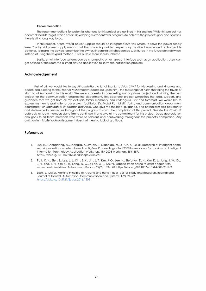
73
Recommendation
The recommendations for potential changes to this project are outlined in this section. While this project has accomplished its target, which entails developing microcontroller programs to achieve the project's goal and priorities, there is still a long way to go.
In this project, future hybrid power supplies should be integrated into this system to solve the power supply issue. The hybrid power supply means that the power is provided respectively by direct source and rechargeable batteries. To make the device remember the owner, fingerprint switches can be substituted in the future control switch. Instead of using the keypad method, it will build a more secure scheme.
Lastly, email interface systems can be changed to other types of interface such as an application. Users can get notified of the room via a smart device application to solve the notification problem.
Acknowledgement
First of all, we would like to say Alhamdulillah, a lot of thanks to Allah S.W.T for His blessing and kindness and
peace and blessing to the Prophet Muhammad (peace be upon him), the messenger of Allah that bring the favors of Islam to all humankind in this world. We were successful in completing our capstone project and winning the best project for the communication engineering department. This capstone project symbolizes the idea, support, and guidance that we get from all my lecturers, family members, and colleagues. First and foremost, we would like to express my hearty gratitude to our project facilitator, Dr. Mohd Rashidi Bin Salim, and communication department coordinator, Dr. Rashidah @ Siti Saedah Binti Arsat, who give me the idea, guidance, and enthusiasm also persistently and determinedly assisted us throughout the progress towards the completion of this project. Despite the Covid-19 outbreak, all team members stand firm to continue still and give all the commitment for this project. Deep appreciation also goes to all team members who were so tolerant and hardworking throughout this project's completion. Any omission in this brief acknowledgment does not mean a lack of gratitude.
References
1. Jun, H., Chengdong, W., Zhongjia, Y., Jiyuan, T., Qiaoqiao, W., & Yun, Z. (2008). Research of intelligent home
security surveillance system based on ZigBee. Proceedings - 2nd 2008 International Symposium on Intelligent Information Technology Application Workshop, IITA 2008 Workshop, 554–557. https://doi.org/10.1109/IITA.Workshops.2008.223
2. Park, K. H., Bien, Z., Lee, J. J., Kim, B. K., Lim, J. T., Kim, J. O., Lee, H., Stefanov, D. H., Kim, D. J., Jung, J. W., Do, J. H., Seo, K. H., Kim, C. H., Song, W. G., & Lee, W. J. (2007). Robotic smart house to assist people with movement disabilities. Autonomous Robots, 22(2), 183–198. https://doi.org/10.1007/s10514-006-9012-9
3. Louis, L. (2016). Working Principle of Arduino and Using it as a Tool for Study and Research. International Journal of Control, Automation, Communication and Systems, 1(2), 21–29. https://doi.org/10.5121/ijcacs.2016.1203