UNIVERSITI TEKNIKAL MALAYSIA MELAKA - eprints.utem.edu.myeprints.utem.edu.my/19799/1/Effect Of...
24
UNIVERSITI TEKNIKAL MALAYSIA MELAKA EFFECT OF CHILLED AIR COOLANT ON SURFACE ROUGHNESS AND TOOL WEAR WHEN MACHINING 2205 DUPLEX STAINLESS STEEL This report submitted in accordance with requirement of the Universiti Teknikal Malaysia Melaka (UTeM) for the Bachelor Degree of Manufacturing Engineering (Manufacturing Process) (Hons.) by UMIRA SYAFIKA BINTI HASHIM B051210032 910330-10-5052 FACULTY OF MANUFACTURING ENGINEERING 2016
Transcript of UNIVERSITI TEKNIKAL MALAYSIA MELAKA - eprints.utem.edu.myeprints.utem.edu.my/19799/1/Effect Of...
UNIVERSITI TEKNIKAL MALAYSIA MELAKA
EFFECT OF CHILLED AIR COOLANT ON SURFACE
ROUGHNESS AND TOOL WEAR WHEN MACHINING 2205
DUPLEX STAINLESS STEEL
This report submitted in accordance with requirement of the Universiti Teknikal
Malaysia Melaka (UTeM) for the Bachelor Degree of Manufacturing Engineering
(Manufacturing Process) (Hons.)
by
UMIRA SYAFIKA BINTI HASHIM
B051210032
910330-10-5052
FACULTY OF MANUFACTURING ENGINEERING
2016
UNIVERSITI TEKNIKAL MALAYSIA MELAKA
BORANG PENGESAHAN STATUS LAPORAN PROJEK SARJANA MUDA
TAJUK: Effect of Chilled Air Coolant on Surface Roughness and Tool Wear When
Machining 2205 Duplex Stainless Steel
SESI PENGAJIAN: 2015/16 Semester 2
Saya UMIRA SYAFIKA BINTI HASHIM
mengaku membenarkan Laporan PSM ini disimpan di Perpustakaan Universiti Teknikal
Malaysia Melaka (UTeM) dengan syarat-syarat kegunaan seperti berikut:
1. Laporan PSM adalah hak milik Universiti Teknikal Malaysia Melaka dan penulis. 2. Perpustakaan Universiti Teknikal Malaysia Melaka dibenarkan membuat salinan untuk
tujuan pengajian sahaja dengan izin penulis. 3. Perpustakaan dibenarkan membuat salinan laporan PSM ini sebagai bahan pertukaran
antara institusi pengajian tinggi.
4. **Sila tandakan (√)
SULIT
TERHAD
/ TIDAK TERHAD
(Mengandungi maklumat yang berdarjah keselamatan atau
kepentingan Malaysiasebagaimana yang termaktub dalam
AKTA RAHSIA RASMI 1972)
(Mengandungi maklumat TERHAD yang telah ditentukan oleh
organisasi/badan di mana penyelidikan dijalankan)
Alamat Tetap:
Lot 6065 Jalan Nazir,
Kampung Sg. Ramal Dalam,
43000, Kajang, Selangor.
Tarikh: 21 JUN 2016
Disahkan oleh:
Cop Rasmi:
Tarikh: 21 JUN 2016
** Jika Laporan PSM ini SULIT atau TERHAD, sila lampirkan surat daripada pihak berkuasa/organisasi
berkenaan dengan menyatakan sekali sebab dan tempoh laporan PSM ini perlu dikelaskan sebagai
SULIT atau TERHAD.
DECLARATION
I hereby, declared this report entitled “Effect of Chilled Air Coolant on Surface
Roughness and Tool Wear When Machining 2205 Duplex Stainless Steel” is the
results of my own research except as cited in references.
Signature :
Author’s Name : Umira Syafika Binti Hashim
Date : 21 JUN 2016
APPROVAL
This report is submitted to the Faculty of Manufacturing Engineering of UTeM
as a partial fulfillment of the requirements for the degree of Bachelor of
Manufacturing Engineering (Manufacturing Process) (Hons.). The member of
the supervisory is as follow:
………………………………
(Dr. Liew Pay Jun)
i
Cecair pemotong adalah penting untuk meningkatkan kemudahan sesuatu alatan
kerja untuk dimesin. Walau bagaimanapun, cecair pemotong konvensional adalah
tidak ekonomik dan berbahaya kepada alam sekitar dan kesihatan. Oleh itu, kaedah
penyejuk bukan konvensional dikaji untuk mengatasi masalah ini. Dalam kajian ini,
kesan penyejuk udara sejuk pada kekasaran permukaan dan kehausan alat apabila
pemesinan 2205 dupleks keluli tahan karat disiasat. Udara termampat disejukkan
dengan menggunakan tiub vorteks. Udara sejuk dan udara panas yang dihasilkan
melalui tiub vorteks daripada sumber udara termampat. Kajian ini juga melibatkan
perbandingan antara prestasi pemesinan antara penyejuk banjir konvensional dan
penyejuk udara sejuk. Ujian telah dijalankan pada mesin perubahan konvensional
dengan TiAlN bersalut alat karbida dan parameter yang berterusan terpilih adalah
kadar suapan, kedalaman pemotongan, dan kelajuan pemotongan. Kekasaran
permukaan dan kehausan alat diukur bagi setiap kali eksperimen dijalankan. Jangka
hayat mata alat dan kemasan permukaan bahan kerja telah dianalisis dalam setiap
keadaan pemotongan. Keputusan eksperimen menunjukkan bahawa penyejuk udara
sejuk memberikan kemasan permukaan yang lebih baik daripada penyejuk banjir
konvensional. Walau bagaimanapun, jangka hayat alat adalah lebih baik apabila
menggunakan penyejuk banjir konvensional berbanding penyejuk udara sejuk. Bagi
kedua-dua kaedah penyejuk, hasilnya menunjukkan penurunan corak untuk
kekasaran permukaan dan kehausan mata alat apabila suhu pendingin udara sejuk
menurun.
ABSTRAK
ii
Cutting fluid is important to enhance machinability. However, conventional cutting
fluid is uneconomical and hazardous to environment and health. Thus, non
conventional coolant method is studied in order to overcome these problems. In this
study, the effect of chilled air coolant on surface roughness and tool wear when
machining 2205 duplex stainless steel is investigated. The compressed air is chilled
by using vortex tube. Cold air and hot air is produced by means of vortex tube from
the source of compressed air. This study also investigated the comparison of
machining performance between conventional flood coolant and chilled air coolant.
The tests were conducted on a conventional turning machine with TiAlN coated
carbide tools and the constant parameters selected were feed rate, cutting depth, and
cutting speed. Surface roughness and tool wear were measured after each run and the
results were analysed. The experiment results showed that chilled air coolant gave
better surface finish compared to conventional flood coolant. However, tool life was
better when using conventional flood coolant compared to chilled air coolant. For
both coolant method, the result showed decreasing trend for surface roughness and
tool wear values when the temperature of chilled air coolant decreased.
ABSTRACT

iii
To my beloved family
DEDICATION
iv
I would like express my deep gratitude to Associate Professor Dr Md Nizam Bin
Abd Rahman for his valuable and constructive suggestion during the planning and
development of this research throughout Projek Sarjna Muda 1. Also, I would like to
express my great appreciation to Dr Liew Pay Jun, who has supported me throughout
Projek Sarjana Muda 2 with her guidance, motivation and knowledge.
Special thanks to Dr Shahir Kasim, Encik Fairuz Dimin, Dr Raja Izamshah Raja
Abdullah and Dr Mohd Hadzley Abu Bakar for their help, guidance and knowledge
which are very useful to me in doing my research.
I would also like to extend my thanks to engineer assistance for helping me handling
the laboratory equipments. And thank you for teaching me how to use the machine
and other equipments.
Lastly, I would like to thank my family and friends for their endless support
throughout completing this research.
DEDICATION
v
TABLE OF CONTENT
Abstrak i
Abstract ii
Dedication iii
Acknowledgement iv
Table of Content v
List of Tables vii
List of Figures ix
List of Equations xi
List of Abbreviations xii
CHAPTER 1: INTRODUCTION
1.1 Introduction 1
1.2 Problem Statement 3
1.3 Objectives 3
1.4 Scope 3
CHAPTER 2: LITERATURE REVIEW
2.1 Turning Process 5
2.2 Machining Parameters 6
2.2.1 Cutting Speed 6
2.2.3 Depth of Cut 7
2.2.4 Studies on Machining Parameter 7
vi
2.3 Workpiece Material 9
2.3.1 Stainless Steel 9
2.4 Cutting Tools 12
2.4.1 Coated Tungsten Carbide 13
2.5 Tool and Work Holding 13
2.5.1 Work Holding 13
2.5.2 Tool holding 14
2.6 Surface Roughness 14
2.7 Tool Wear 16
2.7.1 Flank Wear 16
2.8 Cutting Temperature 19
2.9 Cutting Fluid 20
2.9.1 Types of Cutting Fluid 20
2.9.2 Cooling Method in Machining 21
2.9.4 Studies on Cutting Fluid 25
CHAPTER 3: METHODOLOGY
3.1 Process Flow 31
3.2 Experimental Procedure 33
3.3 Experimental Matrix 33
3.4 Execution of the Experiment 34
3.4.1 Turning Process 34
3.4.2 Cutting Tool 36
3.4.3 Workpiece 37
3.4.4 Coolant 38
3.5 Data Collection 40
3.5.1 Surface Roughness 41
vii
3.5.2 Tool Wear 43
CHAPTER 4: RESULT AND DISCUSSION
4.1 Surface Roughness 44
4.2 Tool Wear 48
CHAPTER 5: CONCLUSION 53
5.1 Conclusion 53
5.2 Recommendation 54
5.3 Sustainability Element 54
REFERENCE 55
viii
LIST OF TABLES
2.1 Machining guideline for face turning duplex stainless steels 8
2.2 Recommended wear land size for different tool material and operations 18
2.3 Summary of studies on cutting fluid 26
3.1 Data collection for surface roughness 33
3.2 Data collection for tool wear 34
3.3 Specifications of Variable Speed Centre Lathe 35
3.4 Constant Parameters 36
3.5 Properties of TiAlN coating 36
3.6 Chemical composition of 2205 duplex stainless steel 37
3.7 Mechanical Properties at Room Temperature, ASTM A 240 37
3.8 Specification of Mitutoyo Profilometer SJ-301 42
ix
LIST OF FIGURES
2.1 Turning operation 6
2.2 Two-phase microstructure of austenite and ferrite grain in duplex
stainless steel 12
2.3 Coordinates used for surface roughness measurement 16
2.4 Standard terminology of surface finish 16
2.5 Traverse direction and stylus movement of surface roughness tester 17
2.6 Types of tool wear 17
2.7 Characterization of flank wear land and rake face wear crater according
to ISO standard 3685l 19
2.8 The variation of the flank wear rate with cutting time 20
2.9 Distribution of heat amongst the chip, workpiece and too 21
2.10 Vortex tube 24
2.11 The structure of the flow inside a counter flow vortex tube 24
2.12 Principal of multi-circulation inside vortex tube 25
3.1 Process flow 32
3.2 Variable speed centre lathe machine 35
3.3 TiAlN coated carbide tool 36
3.4 Flood coolant 38
3.5 Set up for chilled air coolant 39
x
3.6 Air compressor filter regulator 40
3.7 Measure the temperature using thermocouple thermometer 40
3.8 Mitutoyo Profilometer SJ-301 41
3.9 Setup of profilometer during surface roughness measurement 42
3.10 Scanning electron microscope 43
3.11 Maximum Flank Wear, VBmax 43
4.1 Surface roughness under all cutting conditions 45
4.2 Flank wear for all cutting conditions 49
4.3 Flank wear after machining with (a) chilled air coolant at 16°C, 51
(b) chilled air coolant at 14°C, (c) chilled air coolant at 12°C, and (d)
conventional coolant.
xi
LIST OF EQUATIONS
2.1 Formula of Cutting Speed (m/min) 7
2.2 Formula of Feed Rate (mm/min) 7
2.3 Formula of Depth of Cut (mm) 7
2.4 Arithmetic Mean Value (Ra) 16
3.1 Formula of Spindle Speed (rpm) 41
xii
LIST OF ABBREVIATIONS, SYMBOLS, AND
NOMENCLATURES
A. C. Alternate Current
ANOVA Analysis of Variance
ASTM America Standard Testing Material
BUE Built Up Edge
CNC Computer Numerical Control
CVD Chemical Vapor Deposition
D Diameter
DSS Duplex Stainless Steel
f Feed
ISO International Standard Organization
LN Liquid Nitrogen
MQL Minimum Quantity Lubricant
OHNS Oil Hardened Non Shrinkable
PVD Physical Vapor Deposition
Ra Roughness Average
RPM Revolution Per Minute
SEM Scanning Electronic Microscope
TiAlN Titanium Aluminium Nitride

xiii
TiC Titanium Carbide
TiCN Titanium Carbonitride
TiN Titanium Nitride
VBmax Maximum Flank Wear
Vc Cutting Speed
1
This chapter covers the introduction, problem statement, objectives, and scopes
of this project. The chapter overview is also included in this chapter.
1.1 Introduction
Duplex stainless steels (DSS) are chromium- nickel-molybdenum alloys that consist
of balanced amount of austenite and ferrite mixture. By comparing to austenitic
stainless steel alloy, the resistance to chloride stress corrosion cracking and the
mechanical properties of DSS alloys are much higher. DSSs are widely being used in
many industrial sectors like chemical and petrochemical, offshore, pharmaceutical
industry and marine industry.
Machining is a process in which the unwanted raw material is removed by using
sharp cutting tool in order to attain a desired geometry. There are several types of
machining processes such as turning, drilling and milling. Turning is a process where
the cutting tool is fed to a rotating workpiece to generate an external and internal
surface concentric with the axis of rotation. The machine tool used for turning is
called lathe. When the metal is cut, energy is dissipated in overcoming friction
between the tool and workpiece and in deformation of the chip. This energy is
converted to heat, this cause high temperature in the deformation zone as well as the
tool and workpiece. Therefore a cutting fluid or coolant is needed to reduce the
temperature (Stephenson & Agapiou, 2006).
INTRODUCTION
CHAPTER 1
2
Cutting fluid performance in the machining operation is important to enhance the
effectiveness of the machining process. The main purpose of cutting fluid is for
cooling and lubrication but it also helps in improving surface finish, increasing life
span of the cutting tool, and increasing the dimensional accuracy of the workpiece.
Other than that, cutting fluid is used to flush away the chips from the cutting zone,
increase the corrosion resistance of the workpiece and machine, and prevent
formation of build up edge (Johnson et al., 2014).
The general type of cutting fluid consist of water-soluble fluid, neat cutting oil and
gaseous. Water soluble fluids are preferable for operations where cutting speeds are
very high and pressures on the tool are relatively low. Neat cutting oils are straight
mineral oils, or mineral oils with additives which are suitable when the cutting
pressures between chip and cutting tool were very high. Lubrication is important to
reduce the cutting pressure at the cutting zone. At high cutting speed the cutting
fluids are unable to penetrate into the chip–tool interface. Gaseous lubricants are
preferable when the cutting fluid penetration problem is considered but the high cost
of gases made them uneconomical for production applications (Yildiz & Nalbant,
2008).
The use of cutting fluid is not only uneconomical for production application, but it
also harmful to environment as well as the health of the worker. These disadvantages
have made many companies seriously searching for an alternative to replace the
conventional flood coolant method. Therefore the study on chilled air coolant was
done to find the solution to this problem. Most of the works on low temperature
machining are in the cryogenic machining. Even though this is process is promising,
it is cost prohibited in most machining situations. The proposed research will utilize
passive cooling method using vortex tube to chill the compressed air. Since the
source of energy for this application coming from regular compressed air, the cost
associate with it is much lower than that of cryogenic cooling method (Rinaldy et al.,
2016).
3
1.2 Problem Statement
Coolant is important as it helps in increasing tool life and improves surface
roughness. However conventional flood coolant is uneconomical and it brings harm
to the environment and the human health. There were researches that have been done
on low temperature machining study such as cryogenic coolant but to implement this
type of coolant is quite expensive. Therefore, a research on chilled air liquid coolant
will be done to see its effect on the surface roughness and tool wear.
1.3 Objectives
The objectives of this project are:
To investigate the effect of chilled air coolant on surface roughness and tool
wear when machining 2205 duplex stainless steel.
To compare the machining performance between chilled air coolant and
conventional flooded coolant method.
1.4 Scope
This study is carried out using a vegetable oil coolant that is widely used in
machining. The process that is used is turning process, using the TiAlN coated
tungsten carbide grade. The workpiece material is 2205 duplex stainless steel. The
coolant methods that are used are chilled air coolant and flood coolant. The input
variables which are cutting speed, feed rate and depth of cut are set as the constant
parameter. The effect of chilled air coolant on the surface roughness and tool wear
when machining 2205 duplex stainless steel is studied and analysed in detail.
4
1.5 Chapter Overview
Chapter 1 covers the introduction of this investigation. It contains the general
information about the investigation, problem statement, objectives, and scope of the
project.
Chapter 2 covers the literature review for this pro. It contains the literature review for
turning, cutting fluid in turning, studies on cutting fluid and chilled coolant.
Chapter 3 contains the methodology of this project. It contains flow chart, literature
review, execution of the experiment, data collection and data analysis.
Chapter 4 contains the result and discussion for this project. The data from the
experiment is collected and analysed.
Chapter 5 covers the conclusion of this investigation. This chapter also covers the
recommendation for future work and sustainability of this investigation.
5
This chapter contains the literature review of the project which is related to the
objectives and scope of the project. This chapter also tells about the literature review
that will be used in this entire investigation.
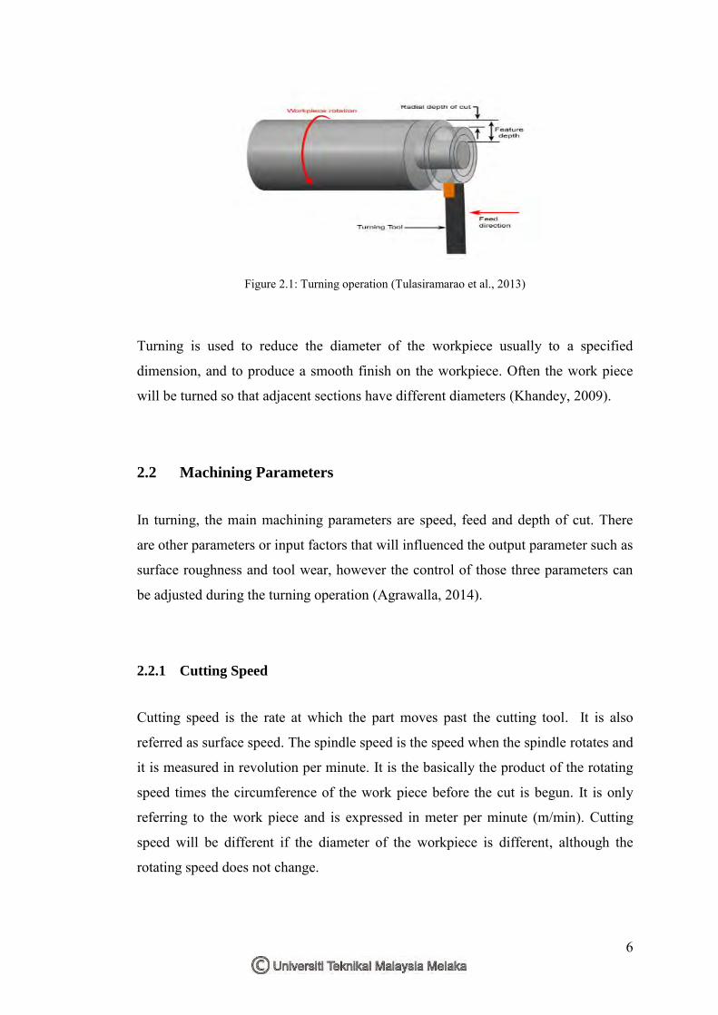
2.1 Turning Process
Turning is one of the most basic machining operations. Turning is a very important
machining process in which a single point cutting tool removes unwanted material
from the surface of a rotating cylindrical work piece. The basic principle of turning
operation is shown in Figure 2.1. The cutting tool is fed linearly in a direction
parallel to the axis of rotation (Ozcelik et al., 2011). It can produce an internal or
external surface concentrically with the axis of rotation. The workpiece is clamped
on a rotating spindle using a chuck, collet, face plate, or between pointed conical
centers. The cutting tool is held on a turret on a translating carriage or in the
tailstock. The carriage moves along the bedways which is parallel to the part axis (Z-
axis) (Stephenson et al., 2006). It can be adjusted axially on the bedways to
accommodate workpieces of various lengths. The feed motion is usually parallel to
the axis of the workpiece.
LITERATURE REVIEW
CHAPTER 2
6
Figure 2.1: Turning operation (Tulasiramarao et al., 2013)
Turning is used to reduce the diameter of the workpiece usually to a specified
dimension, and to produce a smooth finish on the workpiece. Often the work piece
will be turned so that adjacent sections have different diameters (Khandey, 2009).
2.2 Machining Parameters
In turning, the main machining parameters are speed, feed and depth of cut. There
are other parameters or input factors that will influenced the output parameter such as
surface roughness and tool wear, however the control of those three parameters can
be adjusted during the turning operation (Agrawalla, 2014).
2.2.1 Cutting Speed
Cutting speed is the rate at which the part moves past the cutting tool. It is also
referred as surface speed. The spindle speed is the speed when the spindle rotates and
it is measured in revolution per minute. It is the basically the product of the rotating
speed times the circumference of the work piece before the cut is begun. It is only
referring to the work piece and is expressed in meter per minute (m/min). Cutting
speed will be different if the diameter of the workpiece is different, although the
rotating speed does not change.
7
Vc = 𝜋𝐷𝑁
1000 [2.1]
Vc is the cutting speed in turning, D is the initial diameter of the work piece in mm,
and N is the spindle speed in RPM (Agrawalla, 2014).
2.2.2 Feed Rate
Feed rate is the rate of the cutting tool moves through the material that is being cut.
The feed rate units depend on the motion of the tool and workpiece. When the
workpiece rotates, the units are almost distance per spindle revolution. It is usually
expressed in mm per revolution, or mm/rev.
Fm = f.N mm.min-1 [2.2]
Fm represents the feed in mm per minute, f is the feed in mm/rev and N is the spindle
speed in RPM (Khandey, 2009).
2.2.3 Depth of Cut
Depth of cut referred to the thickness of the material that is removed from the
workpiece. The diameter after machining is reduced by twice of the depth of cut due
to the removal of the material from both sides.
dcut = 𝐷−𝑑
2 mm [2.3]
D and d represent initial and final diameter (in mm) of the job respectively (Agrawalla, 2014).
2.2.4 Studies on Machining Parameter
Johnson et al. (2014) studied the optimization of the cutting parameters and fluid
application parameters while turning of Oil Hardened Non shrinkable steel (OHNS)
with minimal cutting fluid application using Taguchi technique. Three different
![PENYATA RASMI PARLIMEN · Menangguhkan Bacaan Kall Yang Kedua dan Ketiga [Ruangan 3509] USUL MENANGGUHKAN MESYUARAT DIBAWAH PERATURAN MESYUARAT 18: Tragedi Pembunuhan Beramal-ramal](https://static.fdokumen.site/doc/165x107/5e560f470cf396091f64f37a/penyata-rasmi-menangguhkan-bacaan-kall-yang-kedua-dan-ketiga-ruangan-3509-usul.jpg)