


Bahasa
Halaman
Undang-undang

1
Modeling large deformation and failure of Expanded Polystyrene Crushable
Foam using LS-DYNA
Qasim H. Shah, A. Topa
Department of Mechanical Engineering Faculty of Engineering, International Islamic
University Malaysia, Jalan Gombak 53100, Kuala Lumpur, MALAYSIA.
Abstract
In the initial phase of the research work quasi-static compression tests were conducted on the
expanded polystyrene (EPS) crushable foam for material characterisation at low strain rates
(8.3x10⁻³~8.3x10⁻² s-1) to obtain the stress strain curves. The resulting stress strain curves
compared well with the ones found in the literature. Numerical analysis of compression tests
were carried out to validate them against experimental results. Additionally gravity-driven
drop tests were carried out using a long rod projectile with semi-spherical end that penetrated
into the EPS foam block. Long rod projectile drop tests were simulated in LS-DYNA by
using suggested parameter enhancements that were able to compute the material damage and
failure response precisely. The material parameters adjustment for a successful modelling has
been reported.
Keywords:
EPS crushable foam, Large deformation, Long rod projectile, Failure modelling, LS-DYNA.
1. Introduction
Crushable foams are suitable solution in the field of shock mitigation and impact absorption
applications because of their incombustibility, cost, complex compression behaviour and high
energy absorption capabilities [1]. In safety applications, accurate predictions of behaviour of
shock absorber materials are extremely important because the experimental work is a
resource hungry process.
___________
Corresponding Author: Tel.:+ 60 (0) 3 6196 4472; fax: +60 (0) 3 6196 4455
E-mail address: [email protected]
2
Throughout the past years, the range of applications of crushable foams has become wider
and larger as engineers and designers keep altering the microstructure of the foam materials
in order to achieve the desired mechanical properties and behaviour that meets the
requirements regarding their applications. Crushable foams are mainly used in cushioning,
impact mitigation, energy absorption, and comfort applications [2].
One way to increase the car body stiffness and crash–worthiness is the utilization of local
reinforcements with synthesized polyurethane foam. The crushable foams have several
advantages over other reinforcement materials because of their high energy absorbing
capabilities, coupled with their low cost and weight [3].
Another important application of the crushable foams is the aircraft runway arrestor systems.
The aircraft might overrun the available runway area during takeoff or landing. Crushable
foam arrestor bed systems mitigate the overrun which prevents accidents involving aircraft
damage and loss of life [4].
In automotive safety, the crushable foams are used in the new Steel And Foam Energy
Reducing (SAFER) barriers. In many NASCAR racetracks, simple crushable polystyrene
insulation foam blocks are placed between the outer steel tube, and the inner concrete wall.
This SAFER barrier is very low in cost and weight and easy to fabricate [5,6].
Another application for the crushable foams is in oil well casing. Heat is generated due to the
normal drilling and production applications. As temperature rises, the trapped fluids tend to
expand and potentially can create a very high pressure. The most e ffective mitigation solution
for this pressure build–up is the application of crushable foam wrap. This will allow the fluid
trapped within the casing annulus to expand. The crushable foam wrap is predetermined to
collapse before any potential dangerous pressure may exist [7].
Extensive experimental work has been conducted to determine the mechanical properties of
expanded polystyrene foams. Difficulties arise in modelling these types of materials because
they are stain rate dependant. Previous studies show that the rate dependant behaviour is
linear with the logarithm of the strain rate [2]. Moreover, the mechanical properties of
polymeric foams depend on their density [8,9]. Therefore, developing the material model
depends on the density of the foams and their applications.
The complexity of the mechanical behaviour of the crushable foams is a consequence of its
cellular structure. Compression is the most common mode of deformation for crushable
3
foams as they are weak in tension and shear. However, tension and shear deformation can
occur due to concentrated compressive loads or the geometry of crushable foams [2].
In pure compression, there are three regions in the stress–strain relationship: linear
compression, stress plateau, and non- linear compression. Poisson‟s ratio is negligible in pure
compression. In pure tension, the material behaves linearly in low deformation. However,
nonlinear behaviour is observed at large deformations [10,11].
In previous work, material models for EPS foams were developed. These models were
proved to be successful in the cases of uniform compression loading and low velocity
localized damage [5,6,12,13]. However, during high velocity localized compression, the
material undergoes a combined mode of compression and tension. Brittle rupture and crack
initiation are experimentally observed in the material [14,15]. Therefore, these material
models need to be improved to include the brittle failure behaviour.
2. Experimental Work
2.1 Quasi-static Compression Test
The quasi-static compression tests were conducted on cubic specimens of EPS crushable
foam with the side length of 100 mm. The average density of the specimen was measured as
12.75 kg/m3. The specimen was compressed until 80% of its initial length. The compression
test was carried out at three different compression rates: 50 mm/min, 250 mm/min, and 500
mm/min and the strain rates for these three compression rates were calculated as 0.00833/s,
0.04167/s, and 0.0833/s, respectively.
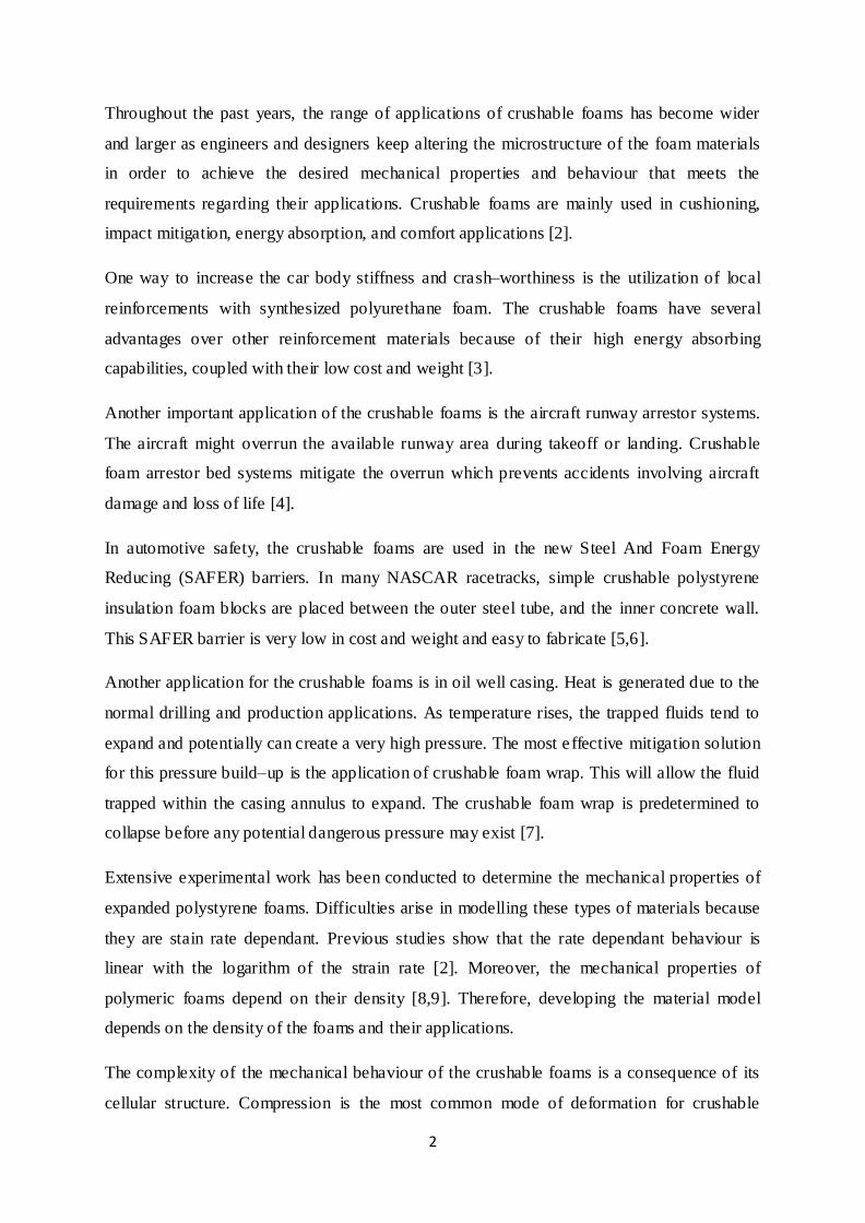
Upon examining the specimen during the compression test, no lateral elongation was
observed as seen in Fig. 1. This proves that EPS crushable foams have zero Poisson‟s ratio.
The volume of the material is not conserved during compression. Instead, the dens ity
increases while the material is compressed. Poisson‟s ratio plays an important role in stress
strain diagrams. The initial and final cross section areas of the EPS crushable foams in
compression remain constant. Thus, the engineering and true stress strain diagrams are
identical.
4
Fig. 1. Quasi static compression test of EPS crushable foam.
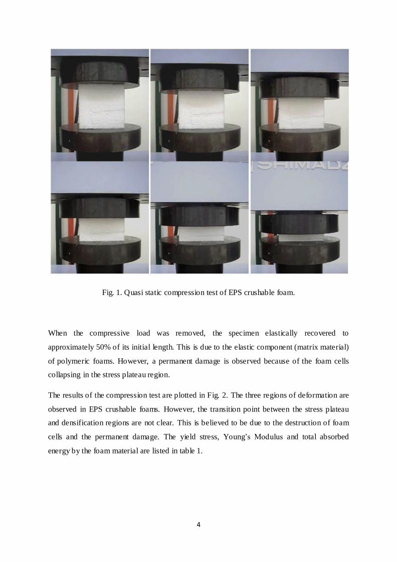
When the compressive load was removed, the specimen elastically recovered to
approximately 50% of its initial length. This is due to the elastic component (matrix material)
of polymeric foams. However, a permanent damage is observed because of the foam cells
collapsing in the stress plateau region.
The results of the compression test are plotted in Fig. 2. The three regions of deformation are
observed in EPS crushable foams. However, the transition point between the stress plateau
and densification regions are not clear. This is believed to be due to the destruction of foam
cells and the permanent damage. The yield stress, Young‟s Modulus and total absorbed
energy by the foam material are listed in table 1.
5
Fig. 2. Rate dependency of EPS crushable foam.
Table 1. Effects of strain rate on yield stress, Young‟s Modulus and absorbed energy.
Strain rate (s-1) Yield stress (MPa) Young‟s Modulus (MPa) Absorbed energy (J)
0.00833 0.020 0.8 104.89
0.04167 0.035 1.4 118.95
0.08333 0.055 2.2 135.06
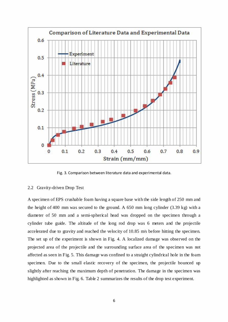
To validate the results of the experiment, the stress strain curve at a strain rate of 0.0833 s-1
was compared to the stress strain curves found in the literature [2]. As observed in Fig. 3,
there is a slight difference in the two curves. This is because of the small difference in the
strain rate and the density of the material. The specimen in the literature had slightly higher
density and the strain rate was a little larger.
6
Fig. 3. Comparison between literature data and experimental data.
2.2 Gravity-driven Drop Test
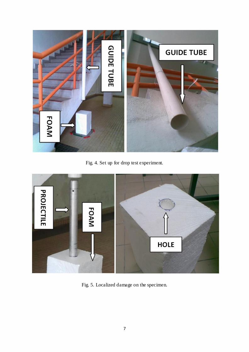
A specimen of EPS crushable foam having a square base with the side length of 250 mm and
the height of 400 mm was secured to the ground. A 650 mm long cylinder (3.39 kg) with a
diameter of 50 mm and a semi-spherical head was dropped on the specimen through a
cylinder tube guide. The altitude of the long rod drop was 6 meters and the projectile
accelerated due to gravity and reached the velocity of 10.85 m/s before hitting the specimen.
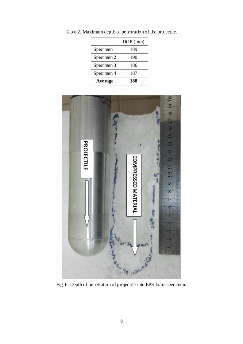
The set up of the experiment is shown in Fig. 4. A localized damage was observed on the
projected area of the projectile and the surrounding surface area of the specimen was not
affected as seen in Fig. 5. This damage was confined to a straight cylindrical hole in the foam
specimen. Due to the small elastic recovery of the specimen, the projectile bounced up
slightly after reaching the maximum depth of penetration. The damage in the specimen was
highlighted as shown in Fig. 6. Table 2 summarizes the results of the drop test experiment.
7
Fig. 4. Set up for drop test experiment.
Fig. 5. Localized damage on the specimen.
8
Table 2. Maximum depth of penetration of the projectile.
DOP (mm)
Specimen 1 189
Specimen 2 190
Specimen 3 186
Specimen 4 187
Average 188
Fig. 6. Depth of penetration of projectile into EPS foam specimen.
9
3. Numerical Simulation
3.1 Compression Test Simulation
The simulation of the quasi static compression test was successfully performed using LS-
Dyna. LS-Dyna provides many material models for different types of foams [16]. However,
based on previous work by Ozturk and Anlas [12], the best candidate for modeling EPS
crushable foam is MAT_CRUSHABLE_FOAM. This material model required the input of
five parameters: density of material, modulus of elasticity, Poisson‟s ratio, stress strain curve,
tensile stress cutoff, and damping coefficient. The first four parameters were found
experimentally. However, tensile cutoff and viscous damping coefficient were obtained from
the literature [12]. The parameters for the material model are listed in Table 3. The model
was finely meshed to obtain accurate results. The lower nodes of the model were fixed while
the upper nodes were given a prescribed motion at 500 mm/min. The results of the simulation
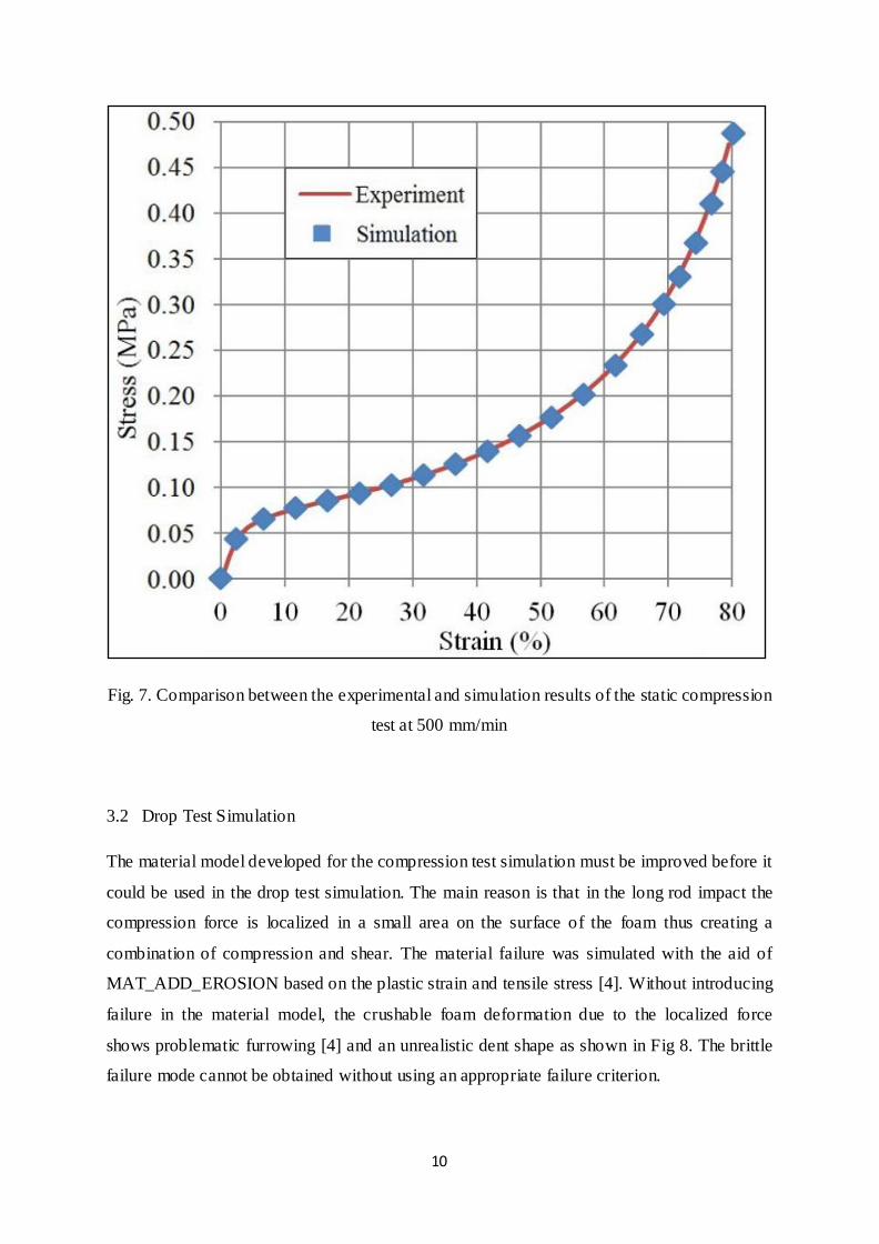
are listed in Fig. 7. A comparison between the simulation and the experimental results show
very small difference and thus verifies the material model developed for compression.
Table 3. Input card for *MAT_CRUSHABLE_FOAM
Parameter Description Value Units
MID Material ID Number
RO Density 12.5 Kg/m3
E Young‟s Modulus 0.0022 GPa
PR Poisson‟s ratio 0
LCID Load curve ID for nominal stress vs. strain
TSC Tensile stress cutoff 0.1x(10)-3 GPa
DAMP Rate sensitivity via damping coefficient 0.5
10
Fig. 7. Comparison between the experimental and simulation results of the static compression
test at 500 mm/min
3.2 Drop Test Simulation
The material model developed for the compression test simulation must be improved before it
could be used in the drop test simulation. The main reason is that in the long rod impact the
compression force is localized in a small area on the surface of the foam thus creating a
combination of compression and shear. The material failure was simulated with the aid of
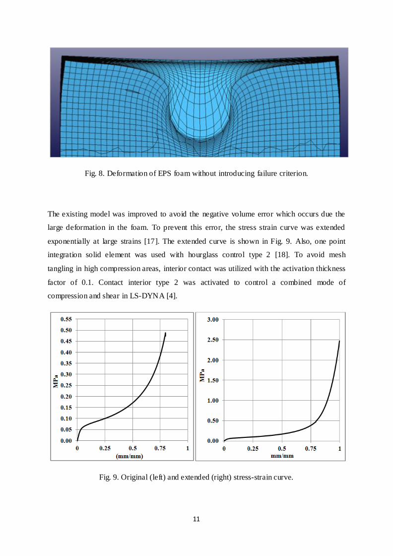
MAT_ADD_EROSION based on the plastic strain and tensile stress [4]. Without introducing
failure in the material model, the crushable foam deformation due to the localized force
shows problematic furrowing [4] and an unrealistic dent shape as shown in Fig 8. The brittle
failure mode cannot be obtained without using an appropriate failure criterion.
11
Fig. 8. Deformation of EPS foam without introducing failure criterion.
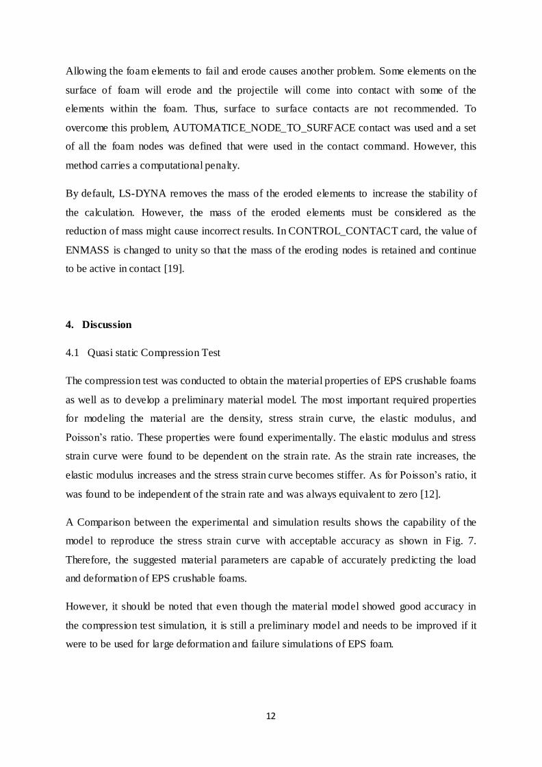
The existing model was improved to avoid the negative volume error which occurs due the
large deformation in the foam. To prevent this error, the stress strain curve was extended
exponentially at large strains [17]. The extended curve is shown in Fig. 9. Also, one point
integration solid element was used with hourglass control type 2 [18]. To avoid mesh
tangling in high compression areas, interior contact was utilized with the activation thickness
factor of 0.1. Contact interior type 2 was activated to control a combined mode of
compression and shear in LS-DYNA [4].
Fig. 9. Original (left) and extended (right) stress-strain curve.
12
Allowing the foam elements to fail and erode causes another problem. Some elements on the
surface of foam will erode and the projectile will come into contact with some of the
elements within the foam. Thus, surface to surface contacts are not recommended. To
overcome this problem, AUTOMATICE_NODE_TO_SURFACE contact was used and a set
of all the foam nodes was defined that were used in the contact command. However, this
method carries a computational penalty.
By default, LS-DYNA removes the mass of the eroded elements to increase the stability of
the calculation. However, the mass of the eroded elements must be considered as the
reduction of mass might cause incorrect results. In CONTROL_CONTACT card, the value of
ENMASS is changed to unity so that the mass of the eroding nodes is retained and continue
to be active in contact [19].
4. Discussion
4.1 Quasi static Compression Test
The compression test was conducted to obtain the material properties of EPS crushable foams
as well as to develop a preliminary material model. The most important required properties
for modeling the material are the density, stress strain curve, the elastic modulus, and
Poisson‟s ratio. These properties were found experimentally. The elastic modulus and stress
strain curve were found to be dependent on the strain rate. As the strain rate increases, the
elastic modulus increases and the stress strain curve becomes stiffer. As for Poisson‟s ratio, it
was found to be independent of the strain rate and was always equivalent to zero [12].
A Comparison between the experimental and simulation results shows the capability of the
model to reproduce the stress strain curve with acceptable accuracy as shown in Fig. 7.
Therefore, the suggested material parameters are capable of accurately predicting the load
and deformation of EPS crushable foams.
However, it should be noted that even though the material model showed good accuracy in
the compression test simulation, it is still a preliminary model and needs to be improved if it
were to be used for large deformation and failure simulations of EPS foam.
13
Failure due to shear or tension must be introduced in the material model. Although crushable
foams are not used under tension or shear loading, localized impact or the geometry of the
crushable foam might result in a combined mode of shear, tension and compression [2].
4.2 Drop Test
The drop test experiment serves as an additional verification of the suggested material
parameters. The first problem encountered in the simulation was the negative volume
problem due to instability. The existing model can withstand compression until only around
80 percent of its original length. This is because the stress strain curve used in the model was
obtained from the compression test in which the compression limit was 80 percent. However,
in the drop test experiment, due to the high kinetic energy of the projectile, the crushable
foam elements might be compressed more than 80 percent of their original length. It may
occur that the strain in the simulation exceeds the last point of the stress-strain curve. If this
happens, LS-DYNA extends the curve linearly with last slope of the curve. This might lead to
relatively small stress values and the negative volume problem might occur.
The negative volume error problem was prevented by adopting two approaches. First, the
stress strain curve was exponentially extended at large strains as shown if Fig. 9. This can be
a very effective approach. Another important parameter which greatly helps in preventing the
negative volume error is by introducing the „contact interior‟ in LS-DYNA. This type of
contact was especially designed to be used for simulating soft materials. The contact interior
type 2 was activated, which was designed to control combined modes of compression and
shear.
In the experiment, the brittle failure was observed in the material due to shear loads. To
simulate this mode of failure, ADD_EROSION was utilized which allows the introduction of
failure criteria in the material model as MAT_CRUSHABLE_FOAM does not allow material
erosion. The failure criteria defined was the maximum tensile stress and maximum plastic
strain. The values of these criteria were found by visual investigation and comparison
between experiment and the simulation. The points at which the material starts to crack and
fail in the experiment were identified, and the respective failure criteria values were
introduced into simulation by trial and error method.
Comparing the projectile depth of penetration in the experiment and simulation validates the
developed material parameters. As shown in Fig. 10, the depth of penetration profile obtained
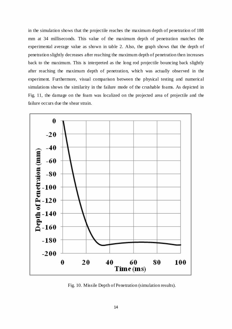
14
in the simulation shows that the projectile reaches the maximum depth of penetration of 188
mm at 34 milliseconds. This value of the maximum depth of penetration matches the
experimental average value as shown in table 2. Also, the graph shows that the depth of
penetration slightly decreases after reaching the maximum depth of penetration then increases
back to the maximum. This is interpreted as the long rod projectile bouncing back slightly
after reaching the maximum depth of penetration, which was actually observed in the
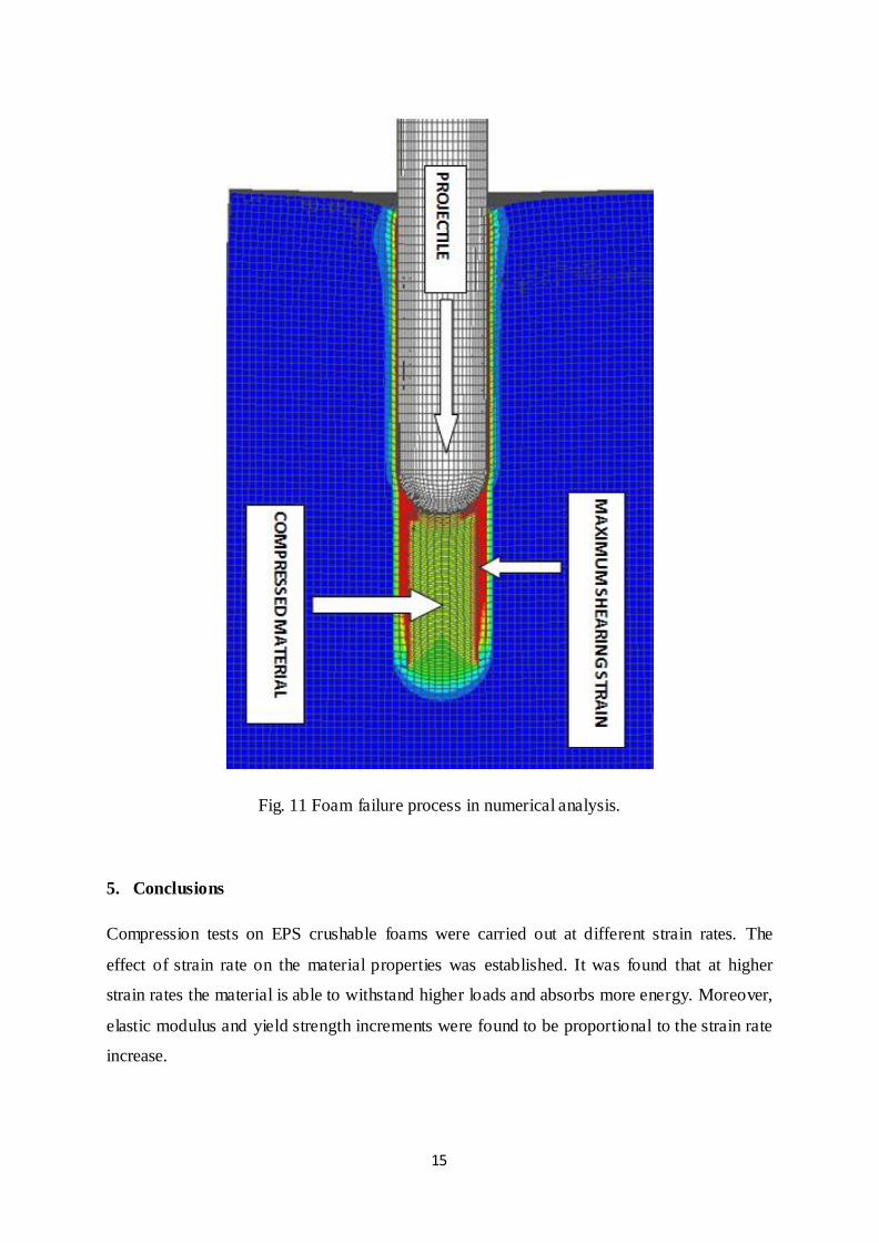
experiment. Furthermore, visual comparison between the physical testing and numerical
simulations shows the similarity in the failure mode of the crushable foams. As depicted in
Fig. 11, the damage on the foam was localized on the projected area of projectile and the
failure occurs due the shear strain.
Fig. 10. Missile Depth of Penetration (simulation results).
15
Fig. 11 Foam failure process in numerical analysis.
5. Conclusions
Compression tests on EPS crushable foams were carried out at different strain rates. The
effect of strain rate on the material properties was established. It was found that at higher
strain rates the material is able to withstand higher loads and absorbs more energy. Moreover,
elastic modulus and yield strength increments were found to be proportional to the strain rate
increase.
16
Compression test simulations were successfully performed and the results were validated by
the experimental work. The material model was capable to reproduce the stress strain curve
with acceptable accuracy.
Drop tests using long rod projectile impact against EPS crushable foam were conducted. The
depth of penetration was recorded and the average value was calculated. The failure mode
and the deformation in the specimen were investigated. Numerical simulations were
performed using the enhanced material parameters along with an appropriate failure criterion
that were able to reproduce the failure modes observed during the experiments. Maximum
depth of penetration obtained in LS-DYNA simulations agreed closely with experimental
work.
6. References
[1] C. Gontier, A. Bouchoua, C. Vinot, A mechanical model for the computation of phenolic foams in compression, International Journal of Mechanical Sciences 43 (2001) 2371–2384.
[2] B. Croop, H. Lobo, Selecting Material Models for the Simulation of Foams in LS-
DYNA, 7th European LS-DYNA Conference (2009) 1-6.
[3] A, Droste, J. Rögger, Crash Performance Increase with Structural BETAFOAMTM,
LS-DYNA Anwenderforum, Frankenthal (2007) 37-44
[4] Matthew Barsotti, M. S., Comparison of FEM and SPH for Modeling a Crushable
Foam Aircraft Arrestor Bed, 11th International LS-DYNA Users Conference (2010) 16
37-54
[5] Robert W. Bielenberg and John D. Reid, Modeling Crushable Foam for the SAFER
Racetrack Barrier, 8th International LS-DYNA Users Conference (2004) 6, 1-10
[6] Robert W. Bielenberg and John D Reid, Modeling Rebound of Foam Backed Race
Track Barriers, 8th International LS-DYNA Users Conference (2008)6, 42-50
[7] G. Downie. (2009, April 1), Crushable Foam Wrap Mitigates Subsea Casing Failures
[Online]. Available: http://www.epmag.com/Production/Crushable- foam-wrap-
mitigates-subsea-casing-failures_33864
[8] Q. Liu, G. Subhash, X. L. Gao, A parametric study on crushability of open-cell
structural polymeric foams. J Porous Mater 2005;12(3):233–248.
17
[9] L. Aktay, A.K. Toksoy, M. Gu¨den, Quasi-static Axial Crushing of Extruded
Polystyrene Foam-filled Thin-Walled Aluminum Tubes: Experimental and Numerical
Analysis, Materials and Design 27 (2006) 556–565
[10] Z.H. Tu, V.P.W Shim, C.T. Lim, Plastic Deformation Modes in Rigid Polyurethane
Foam under Static Loading, International Journal of Solids and Structures 38 (2001)
9267-9279
[11] M. Wronski, A New Hypoelastic Model of The Mechanical Behavior of Polyurethane
Foams, Computational Materials Science 5 (1996) 271-276
[12] U. E. Ozturk, G. Anlas, Finite Element Analysis of Expanded Polystyrene Foam Under
Multiple Compressive Loading and Unloading, Materials and Design 32 (2011) 773–
780.
[13] G. Slik, G. Vogel, V. Chawda, Material Model Validation of a High Efficient Energy
Absorbing Foam, Materials Engineering Centre, 5th LS-DYNA Forum, Ulm 2006
[14] V. I. Rizov, Low Velocity Localized Impact Study of Cellular Foams, Materials and
Design 28 (2007) 2632–2640
[15] P.A. Du Bois, S. Kolling, M. Koesters, T. Frank, Material behaviour of polymers under
impact loading, International Journal of Impact Engineering 32 (2006) 725–740
[16] LS-DYNA Theory Manual Version 970, Livermore Software Technology corporation;
2003
[17] S. Bala. (2006, October 12), Best Practices for Modeling Recoverable Low Density
Foams – By Example [Online]. Available: http://blog2.d3view.com/best-practices- for-
modeling-recoverable- low-density- foams-by-example/
[18] K. Weimar, J. Day. (2003, August 10), Negative volumes in brick elements [Online].
Available: http://www.dynasupport.com/howtos/element/negativ-volumes- in-brick-
elements
[19] Q. H. Shah, H. Abid, “LS-PrePost & LS-DYNA Tips,” in LS-DYNA for beginners: An
Insight Into Ls-Prepost and Ls-Dyna. Saarbrücken, Germany: Lambert (2012), pp. 116
Top Related