Performance Experiment and Numerical Prediction of the ...
7
Sains Malaysiana 45(11)(2016): 1655–1661 Performance Experiment and Numerical Prediction of the Copper Based Hair Cell Sensor for Underwater Sensing (Eksperimen Prestasi dan Ramalan Berangka Pengesan Sel Rambut Berasaskan Kuprum untuk Penderiaan dalam Air) MOHD NORZAIDI MAT NAWI*, ASRULNIZAM ABD MANAF, MOHD RIZAL ARSHAD & OTHMAN SIDEK ABSTRACT This paper demonstrates the performance experiment and numerical prediction of the copper based hair cell for underwater sensing. Generally, the hair cell consists of the single cantilever that attached perpendicular to the substrate and integrated with strain gage (Kyowa type: KFG-1N-120-C1-11). The hair cell sensor was simulated using different flow rates to study the pressure and the strain distribution acting on the sensor by using computational fluid dynamic and finite element analysis approach. High performance sensor can be achieved by increasing the length of the hair cell and also using low Young Modulus material. The hair cell has been fabricated for dimension of 8000 μm length, 2000 μm width and 100 μm thickness, where the copper was chosen due to its mechanical properties. The response time for a sensor to respond completely to a change in input is about 50 m/s and the sensitivity in terms of output voltage and input flow rate is 0.2 mV/ms -1 . Also, the result obtained in the simulation is aligned with the experimental result. The experiment for moving object detection proved that this sensor is able to detect the moving object and it is necessary for underwater applications, especially for monitoring and surveillance. Keywords: Hair cell; moving object detection; strain gage; underwater sensing ABSTRAK Kertas ini membincangkan eksperimen prestasi dan ramalan berangka untuk sel rambut berasaskan kuprum untuk pengesanan bawah air. Secara umumnya, sel rambut itu terdiri daripada julur tunggal yang tegak berserenjang dengan substrat dan disepadukan dengan tolok terikan (jenis Kyowa: KFG-1N-120-C1-11). Pengesan sel rambut telah disimulasi menggunakan kadar aliran yang berbeza untuk mengkaji tekanan dan taburan terikan yang bertindak ke atas pengesan dengan menggunakan pengiraan dinamik bendalir dan kaedah unsur terhingga. Pengesan berprestasi tinggi boleh dicapai dengan meningkatkan panjang sel rambut dan juga menggunakan bahan Young Modulus yang rendah. Sel rambut telah direka bagi ukuran panjang 8000 μm, lebar 2000 μm dan tebal 100 μm, dengan kuprum telah dipilih kerana sifat mekaniknya. Masa tindak balas untuk pengesan bertindak balas sepenuhnya kepada perubahan input adalah kira-kira 50 m/s dan sensitiviti daripada segi keluaran voltan dan kadar aliran masukan adalah 0.2 mV/ms -1 . Keputusan yang diperoleh daripada simulasi juga adalah sejajar dengan keputusan eksperimen. Eksperimen untuk pengesanan objek bergerak membuktikan bahawa pengesan ini boleh mengesan objek yang bergerak dan ini adalah perlu bagi aplikasi bawah air, terutamanya untuk pemantauan dan pengawasan. Kata kunci: Pengesan bawah air; pengesanan objek bergerak; sel rambut; tolok terikan INTRODUCTION In recent years, the biomimetic or biological structures of nature has given major contribution to the development of the underwater sensor with new inspiration where it helps to improve their capability and performance. As an example, the artificial lateral line flow system for flow imaging on the fish body that help the underwater vehicle to perform in total darkness. It function is to determine the distance, location and direction of moving objects relative to a stationary target (Coombs 2001). Generally, there are many types of underwater sensor that have been developed including the acoustic sensor, optical sensor and electrochemical sensor. Acoustics are utilized to fulfill the needs of sonar and underwater communications for both capacitive type and piezoelectric type (Arshad 2009). Flow sensor also important and it was used for measuring the flow velocity and as detection for the underwater vehicles. The lateral line system consists of superficial and canal neuromast. Superficial neuromasts located in the skin is in direct contact with the stream while canal neuromasts exist in the sub-epidermal canals connecting pore openings on the skin surface. Superficial neuromast, a fundamental mechanoreceptor, consists of hair cell attach to a neuron. If the hair cell is bent by the local fluid flow, the neuron that attached to the cilium stretches and produces action potentials (Fan et al. 2002). By using this principle, many
Transcript of Performance Experiment and Numerical Prediction of the ...

Sains Malaysiana 45(11)(2016): 1655–1661
Performance Experiment and Numerical Prediction of the Copper Based Hair Cell Sensor for Underwater Sensing(Eksperimen Prestasi dan Ramalan Berangka Pengesan Sel Rambut
Berasaskan Kuprum untuk Penderiaan dalam Air)
MOHD NORZAIDI MAT NAWI*, ASRULNIZAM ABD MANAF, MOHD RIZAL ARSHAD & OTHMAN SIDEK
ABSTRACT
This paper demonstrates the performance experiment and numerical prediction of the copper based hair cell for underwater sensing. Generally, the hair cell consists of the single cantilever that attached perpendicular to the substrate and integrated with strain gage (Kyowa type: KFG-1N-120-C1-11). The hair cell sensor was simulated using different flow rates to study the pressure and the strain distribution acting on the sensor by using computational fluid dynamic and finite element analysis approach. High performance sensor can be achieved by increasing the length of the hair cell and also using low Young Modulus material. The hair cell has been fabricated for dimension of 8000 μm length, 2000 μm width and 100 μm thickness, where the copper was chosen due to its mechanical properties. The response time for a sensor to respond completely to a change in input is about 50 m/s and the sensitivity in terms of output voltage and input flow rate is 0.2 mV/ms-1. Also, the result obtained in the simulation is aligned with the experimental result. The experiment for moving object detection proved that this sensor is able to detect the moving object and it is necessary for underwater applications, especially for monitoring and surveillance.
Keywords: Hair cell; moving object detection; strain gage; underwater sensing
ABSTRAK
Kertas ini membincangkan eksperimen prestasi dan ramalan berangka untuk sel rambut berasaskan kuprum untuk pengesanan bawah air. Secara umumnya, sel rambut itu terdiri daripada julur tunggal yang tegak berserenjang dengan substrat dan disepadukan dengan tolok terikan (jenis Kyowa: KFG-1N-120-C1-11). Pengesan sel rambut telah disimulasi menggunakan kadar aliran yang berbeza untuk mengkaji tekanan dan taburan terikan yang bertindak ke atas pengesan dengan menggunakan pengiraan dinamik bendalir dan kaedah unsur terhingga. Pengesan berprestasi tinggi boleh dicapai dengan meningkatkan panjang sel rambut dan juga menggunakan bahan Young Modulus yang rendah. Sel rambut telah direka bagi ukuran panjang 8000 μm, lebar 2000 μm dan tebal 100 μm, dengan kuprum telah dipilih kerana sifat mekaniknya. Masa tindak balas untuk pengesan bertindak balas sepenuhnya kepada perubahan input adalah kira-kira 50 m/s dan sensitiviti daripada segi keluaran voltan dan kadar aliran masukan adalah 0.2 mV/ms-1. Keputusan yang diperoleh daripada simulasi juga adalah sejajar dengan keputusan eksperimen. Eksperimen untuk pengesanan objek bergerak membuktikan bahawa pengesan ini boleh mengesan objek yang bergerak dan ini adalah perlu bagi aplikasi bawah air, terutamanya untuk pemantauan dan pengawasan.
Kata kunci: Pengesan bawah air; pengesanan objek bergerak; sel rambut; tolok terikan
INTRODUCTION
In recent years, the biomimetic or biological structures of nature has given major contribution to the development of the underwater sensor with new inspiration where it helps to improve their capability and performance. As an example, the artificial lateral line flow system for flow imaging on the fish body that help the underwater vehicle to perform in total darkness. It function is to determine the distance, location and direction of moving objects relative to a stationary target (Coombs 2001). Generally, there are many types of underwater sensor that have been developed including the acoustic sensor, optical sensor and electrochemical sensor. Acoustics are utilized to fulfill the
needs of sonar and underwater communications for both capacitive type and piezoelectric type (Arshad 2009). Flow sensor also important and it was used for measuring the flow velocity and as detection for the underwater vehicles. The lateral line system consists of superficial and canal neuromast. Superficial neuromasts located in the skin is in direct contact with the stream while canal neuromasts exist in the sub-epidermal canals connecting pore openings on the skin surface. Superficial neuromast, a fundamental mechanoreceptor, consists of hair cell attach to a neuron. If the hair cell is bent by the local fluid flow, the neuron that attached to the cilium stretches and produces action potentials (Fan et al. 2002). By using this principle, many
1656
researchers have developed the sensor based on hair cell. The commonly materials such as silicon and SU-8 are commonly being used as a material for the structure of hair cell (Tao & Yu 2012). SU-8 is a negative photoresist where it is commonly used in sensors technology (Lorenz 1997). The general structure of hair cell consists of a single hair cell that perpendicular to the substrate and using strain gage or piezo resistive to measure the strain due to the deflection of hair cells. In this paper, we present the development of hair cell using copper material and integrated with conventional strain gage. The different dimension and material was simulated using FEM and CFD method. The finalize design was fabricated and tested for several flow rates.
OVERVIEW OF THE BIOMIMETIC FLOW SENSOR
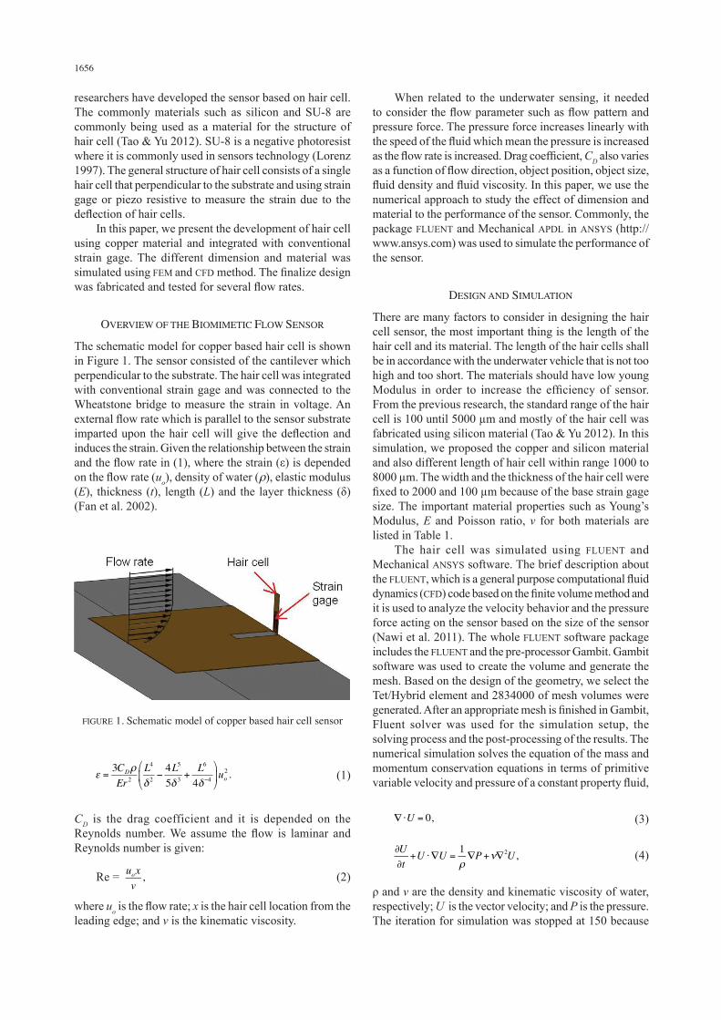
The schematic model for copper based hair cell is shown in Figure 1. The sensor consisted of the cantilever which perpendicular to the substrate. The hair cell was integrated with conventional strain gage and was connected to the Wheatstone bridge to measure the strain in voltage. An external flow rate which is parallel to the sensor substrate imparted upon the hair cell will give the deflection and induces the strain. Given the relationship between the strain and the flow rate in (1), where the strain (ε) is depended on the flow rate (uo), density of water (ρ), elastic modulus (E), thickness (t), length (L) and the layer thickness (δ) (Fan et al. 2002).
When related to the underwater sensing, it needed to consider the flow parameter such as flow pattern and pressure force. The pressure force increases linearly with the speed of the fluid which mean the pressure is increased as the flow rate is increased. Drag coefficient, CD also varies as a function of flow direction, object position, object size, fluid density and fluid viscosity. In this paper, we use the numerical approach to study the effect of dimension and material to the performance of the sensor. Commonly, the package FLUENT and Mechanical APDL in ANSYS (http://www.ansys.com) was used to simulate the performance of the sensor.
DESIGN AND SIMULATION
There are many factors to consider in designing the hair cell sensor, the most important thing is the length of the hair cell and its material. The length of the hair cells shall be in accordance with the underwater vehicle that is not too high and too short. The materials should have low young Modulus in order to increase the efficiency of sensor. From the previous research, the standard range of the hair cell is 100 until 5000 µm and mostly of the hair cell was fabricated using silicon material (Tao & Yu 2012). In this simulation, we proposed the copper and silicon material and also different length of hair cell within range 1000 to 8000 µm. The width and the thickness of the hair cell were fixed to 2000 and 100 µm because of the base strain gage size. The important material properties such as Young’s Modulus, E and Poisson ratio, v for both materials are listed in Table 1. The hair cell was simulated using FLUENT and Mechanical ANSYS software. The brief description about the FLUENT, which is a general purpose computational fluid dynamics (CFD) code based on the finite volume method and it is used to analyze the velocity behavior and the pressure force acting on the sensor based on the size of the sensor (Nawi et al. 2011). The whole FLUENT software package includes the FLUENT and the pre-processor Gambit. Gambit software was used to create the volume and generate the mesh. Based on the design of the geometry, we select the Tet/Hybrid element and 2834000 of mesh volumes were generated. After an appropriate mesh is finished in Gambit, Fluent solver was used for the simulation setup, the solving process and the post-processing of the results. The numerical simulation solves the equation of the mass and momentum conservation equations in terms of primitive variable velocity and pressure of a constant property fluid,
(3)
(4)
ρ and v are the density and kinematic viscosity of water, respectively; U is the vector velocity; and P is the pressure. The iteration for simulation was stopped at 150 because
FIGURE 1. Schematic model of copper based hair cell sensor
(1)
CD is the drag coefficient and it is depended on the Reynolds number. We assume the flow is laminar and Reynolds number is given:
Re = (2)
where uo is the flow rate; x is the hair cell location from the leading edge; and v is the kinematic viscosity.
1657
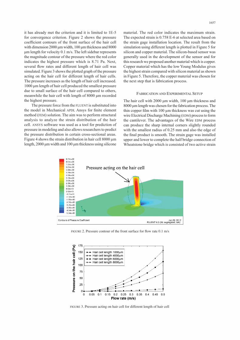
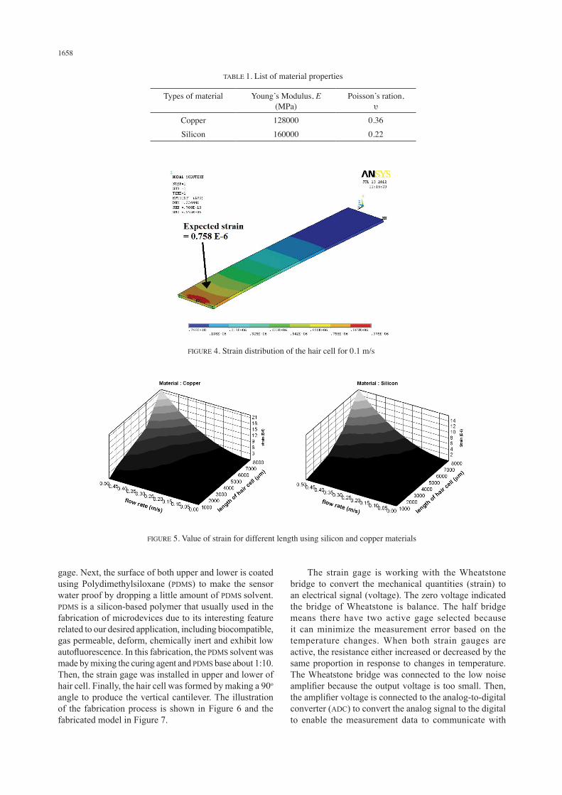
it has already met the criterion and it is limited to 1E-5 for convergence criterion. Figure 2 shows the pressure coefficient contours of the front surface of the hair cell with dimension 2000 μm width, 100 μm thickness and 8000 μm length for velocity 0.1 m/s. The left sidebar represents the magnitude contour of the pressure where the red color indicates the highest pressure which is 8.71 Pa. Next, several flow rates and different length of hair cell was simulated. Figure 3 shows the plotted graph of the pressure acting on the hair cell for different length of hair cells. The pressure increases as the length of hair cell increased. 1000 μm length of hair cell produced the smallest pressure due to small surface of the hair cell compared to others, meanwhile the hair cell with length of 8000 μm recorded the highest pressure. The pressure force from the FLUENT is substituted into the model in Mechanical APDL Ansys for finite element method (FEM) solution. The aim was to perform structural analysis to analyze the strain distribution of the hair cell. ANSYS software was used as a tool for prediction of pressure in modeling and also allows researchers to predict the pressure distribution in certain cross-sectional areas. Figure 4 shows the strain distribution in hair cell 8000 µm length, 2000 μm width and 100 μm thickness using silicone
material. The red color indicates the maximum strain. The expected strain is 0.758 E-6 at selected area based on the strain gage installation location. The result from the simulation using different length is plotted in Figure 5 for silicon and copper material. The silicon-based sensor was generally used in the development of the sensor and for this research we proposed another material which is copper. Copper material which has the low Young Modulus gives the highest strain compared with silicon material as shown in Figure 5. Therefore, the copper material was chosen for the next step that is fabrication process.
FABRICATION AND EXPERIMENTAL SETUP
The hair cell with 2000 μm width, 100 μm thickness and 8000 μm length was chosen for the fabrication process. The thin copper film with 100 µm thickness was cut using the wire Electrical Discharge Machining (EDM) process to form the cantilever. The advantages of the Wire EDM process can produce the sharp internal corners slightly rounded with the smallest radius of 0.25 mm and also the edge of the final product is smooth. The strain gage was installed upper and lower to complete the half bridge connection of Wheatstone bridge which is consisted of two active strain
FIGURE 2. Pressure contour of the front surface for flow rate 0.1 m/s
FIGURE 3. Pressure acting on hair cell for different length of hair cell
1658
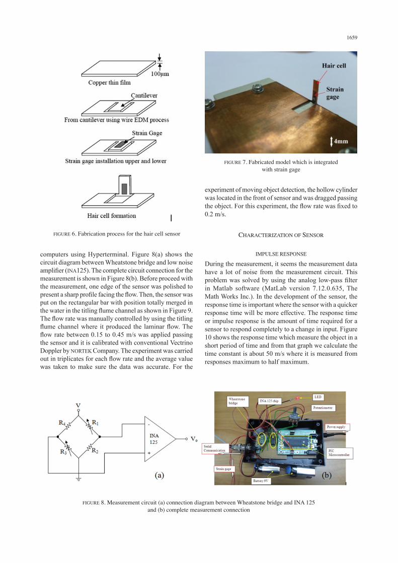
gage. Next, the surface of both upper and lower is coated using Polydimethylsiloxane (PDMS) to make the sensor water proof by dropping a little amount of PDMS solvent. PDMS is a silicon-based polymer that usually used in the fabrication of microdevices due to its interesting feature related to our desired application, including biocompatible, gas permeable, deform, chemically inert and exhibit low autofluorescence. In this fabrication, the PDMS solvent was made by mixing the curing agent and PDMS base about 1:10. Then, the strain gage was installed in upper and lower of hair cell. Finally, the hair cell was formed by making a 90o angle to produce the vertical cantilever. The illustration of the fabrication process is shown in Figure 6 and the fabricated model in Figure 7.
The strain gage is working with the Wheatstone bridge to convert the mechanical quantities (strain) to an electrical signal (voltage). The zero voltage indicated the bridge of Wheatstone is balance. The half bridge means there have two active gage selected because it can minimize the measurement error based on the temperature changes. When both strain gauges are active, the resistance either increased or decreased by the same proportion in response to changes in temperature. The Wheatstone bridge was connected to the low noise amplifier because the output voltage is too small. Then, the amplifier voltage is connected to the analog-to-digital converter (ADC) to convert the analog signal to the digital to enable the measurement data to communicate with
TABLE 1. List of material properties
Types of material Young’s Modulus, E (MPa)
Poisson’s ration, υ
Copper 128000 0.36Silicon 160000 0.22
FIGURE 4. Strain distribution of the hair cell for 0.1 m/s
FIGURE 5. Value of strain for different length using silicon and copper materials
1659
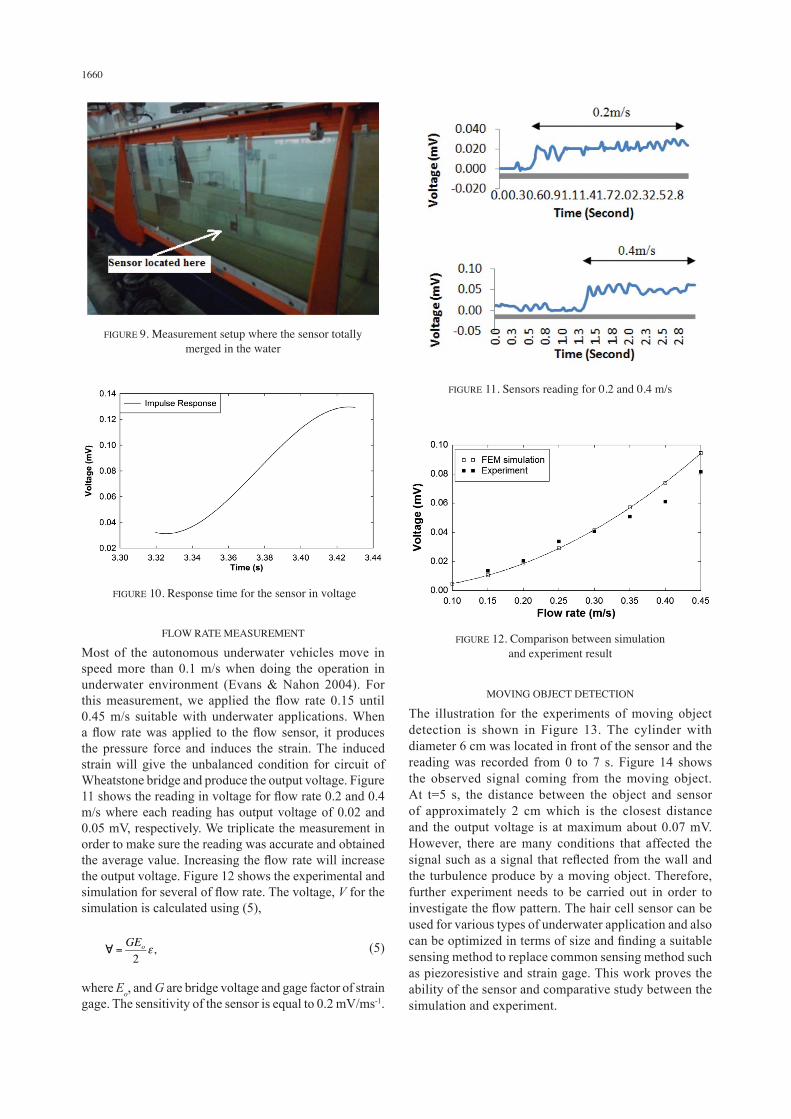
computers using Hyperterminal. Figure 8(a) shows the circuit diagram between Wheatstone bridge and low noise amplifier (INA125). The complete circuit connection for the measurement is shown in Figure 8(b). Before proceed with the measurement, one edge of the sensor was polished to present a sharp profile facing the flow. Then, the sensor was put on the rectangular bar with position totally merged in the water in the titling flume channel as shown in Figure 9. The flow rate was manually controlled by using the titling flume channel where it produced the laminar flow. The flow rate between 0.15 to 0.45 m/s was applied passing the sensor and it is calibrated with conventional Vectrino Doppler by NORTEK Company. The experiment was carried out in triplicates for each flow rate and the average value was taken to make sure the data was accurate. For the
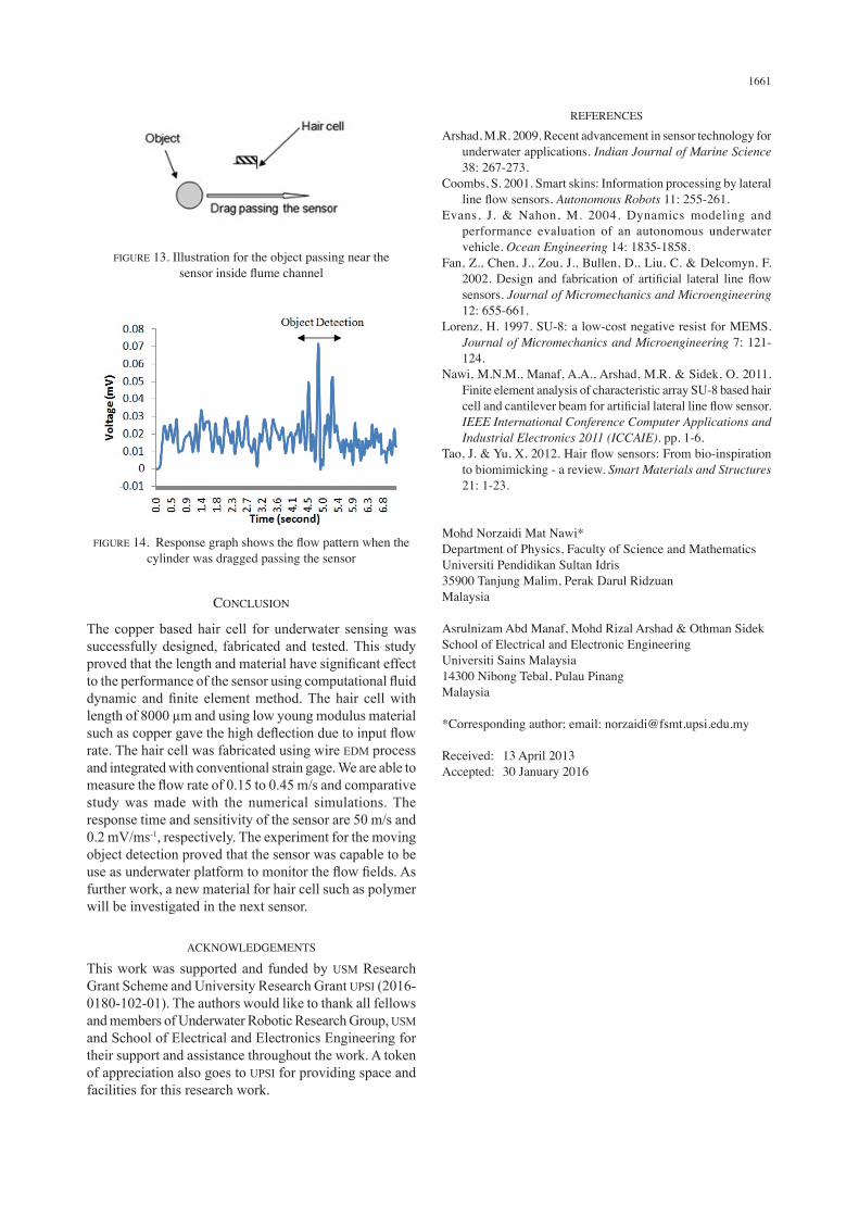
experiment of moving object detection, the hollow cylinder was located in the front of sensor and was dragged passing the object. For this experiment, the flow rate was fixed to 0.2 m/s.
CHARACTERIZATION OF SENSOR
IMPULSE RESPONSE
During the measurement, it seems the measurement data have a lot of noise from the measurement circuit. This problem was solved by using the analog low-pass filter in Matlab software (MatLab version 7.12.0.635, The Math Works Inc.). In the development of the sensor, the response time is important where the sensor with a quicker response time will be more effective. The response time or impulse response is the amount of time required for a sensor to respond completely to a change in input. Figure 10 shows the response time which measure the object in a short period of time and from that graph we calculate the time constant is about 50 m/s where it is measured from responses maximum to half maximum.
FIGURE 6. Fabrication process for the hair cell sensor
FIGURE 7. Fabricated model which is integrated with strain gage
FIGURE 8. Measurement circuit (a) connection diagram between Wheatstone bridge and INA 125 and (b) complete measurement connection
1660
FLOW RATE MEASUREMENT
Most of the autonomous underwater vehicles move in speed more than 0.1 m/s when doing the operation in underwater environment (Evans & Nahon 2004). For this measurement, we applied the flow rate 0.15 until 0.45 m/s suitable with underwater applications. When a flow rate was applied to the flow sensor, it produces the pressure force and induces the strain. The induced strain will give the unbalanced condition for circuit of Wheatstone bridge and produce the output voltage. Figure 11 shows the reading in voltage for flow rate 0.2 and 0.4 m/s where each reading has output voltage of 0.02 and 0.05 mV, respectively. We triplicate the measurement in order to make sure the reading was accurate and obtained the average value. Increasing the flow rate will increase the output voltage. Figure 12 shows the experimental and simulation for several of flow rate. The voltage, V for the simulation is calculated using (5),
(5)
where Eo, and G are bridge voltage and gage factor of strain gage. The sensitivity of the sensor is equal to 0.2 mV/ms-1.
MOVING OBJECT DETECTION
The illustration for the experiments of moving object detection is shown in Figure 13. The cylinder with diameter 6 cm was located in front of the sensor and the reading was recorded from 0 to 7 s. Figure 14 shows the observed signal coming from the moving object. At t=5 s, the distance between the object and sensor of approximately 2 cm which is the closest distance and the output voltage is at maximum about 0.07 mV. However, there are many conditions that affected the signal such as a signal that reflected from the wall and the turbulence produce by a moving object. Therefore, further experiment needs to be carried out in order to investigate the flow pattern. The hair cell sensor can be used for various types of underwater application and also can be optimized in terms of size and finding a suitable sensing method to replace common sensing method such as piezoresistive and strain gage. This work proves the ability of the sensor and comparative study between the simulation and experiment.
FIGURE 9. Measurement setup where the sensor totally merged in the water
FIGURE 10. Response time for the sensor in voltage
FIGURE 11. Sensors reading for 0.2 and 0.4 m/s
FIGURE 12. Comparison between simulation and experiment result
1661
CONCLUSION
The copper based hair cell for underwater sensing was successfully designed, fabricated and tested. This study proved that the length and material have significant effect to the performance of the sensor using computational fluid dynamic and finite element method. The hair cell with length of 8000 µm and using low young modulus material such as copper gave the high deflection due to input flow rate. The hair cell was fabricated using wire EDM process and integrated with conventional strain gage. We are able to measure the flow rate of 0.15 to 0.45 m/s and comparative study was made with the numerical simulations. The response time and sensitivity of the sensor are 50 m/s and 0.2 mV/ms-1, respectively. The experiment for the moving object detection proved that the sensor was capable to be use as underwater platform to monitor the flow fields. As further work, a new material for hair cell such as polymer will be investigated in the next sensor.
ACKNOWLEDGEMENTS
This work was supported and funded by USM Research Grant Scheme and University Research Grant UPSI (2016-0180-102-01). The authors would like to thank all fellows and members of Underwater Robotic Research Group, USM and School of Electrical and Electronics Engineering for their support and assistance throughout the work. A token of appreciation also goes to UPSI for providing space and facilities for this research work.
REFERENCES
Arshad, M.R. 2009. Recent advancement in sensor technology for underwater applications. Indian Journal of Marine Science 38: 267-273.
Coombs, S. 2001. Smart skins: Information processing by lateral line flow sensors. Autonomous Robots 11: 255-261.
Evans, J. & Nahon, M. 2004. Dynamics modeling and performance evaluation of an autonomous underwater vehicle. Ocean Engineering 14: 1835-1858.
Fan, Z., Chen, J., Zou, J., Bullen, D., Liu, C. & Delcomyn, F. 2002. Design and fabrication of artificial lateral line flow sensors. Journal of Micromechanics and Microengineering 12: 655-661.
Lorenz, H. 1997. SU-8: a low-cost negative resist for MEMS. Journal of Micromechanics and Microengineering 7: 121-124.
Nawi, M.N.M., Manaf, A.A., Arshad, M.R. & Sidek, O. 2011. Finite element analysis of characteristic array SU-8 based hair cell and cantilever beam for artificial lateral line flow sensor. IEEE International Conference Computer Applications and Industrial Electronics 2011 (ICCAIE). pp. 1-6.
Tao, J. & Yu, X. 2012. Hair flow sensors: From bio-inspiration to biomimicking - a review. Smart Materials and Structures 21: 1-23.
Mohd Norzaidi Mat Nawi*Department of Physics, Faculty of Science and Mathematics Universiti Pendidikan Sultan Idris35900 Tanjung Malim, Perak Darul Ridzuan Malaysia
Asrulnizam Abd Manaf, Mohd Rizal Arshad & Othman SidekSchool of Electrical and Electronic EngineeringUniversiti Sains Malaysia14300 Nibong Tebal, Pulau Pinang Malaysia
*Corresponding author; email: [email protected]
Received: 13 April 2013Accepted: 30 January 2016
FIGURE 13. Illustration for the object passing near the sensor inside flume channel
FIGURE 14. Response graph shows the flow pattern when the cylinder was dragged passing the sensor